EP1069066A1 - Aufzugsanlage mit Schachttüren - Google Patents
Aufzugsanlage mit Schachttüren Download PDFInfo
- Publication number
- EP1069066A1 EP1069066A1 EP00114347A EP00114347A EP1069066A1 EP 1069066 A1 EP1069066 A1 EP 1069066A1 EP 00114347 A EP00114347 A EP 00114347A EP 00114347 A EP00114347 A EP 00114347A EP 1069066 A1 EP1069066 A1 EP 1069066A1
- Authority
- EP
- European Patent Office
- Prior art keywords
- shaft
- door
- elevator system
- wall
- doors according
- Prior art date
- Legal status (The legal status is an assumption and is not a legal conclusion. Google has not performed a legal analysis and makes no representation as to the accuracy of the status listed.)
- Granted
Links
Images

Classifications
-
- B—PERFORMING OPERATIONS; TRANSPORTING
- B66—HOISTING; LIFTING; HAULING
- B66B—ELEVATORS; ESCALATORS OR MOVING WALKWAYS
- B66B13/00—Doors, gates, or other apparatus controlling access to, or exit from, cages or lift well landings
- B66B13/30—Constructional features of doors or gates
- B66B13/303—Details of door panels
Definitions
- the invention relates to an elevator system with shaft doors according to the preamble of claim 1.
- Shaft doors with preferably two or four door leaves are regularly provided.
- Telescopic doors are characterized by the fact that the required lateral crossing distance is small in relation to the width of the cabin access opening to be covered.
- the telescopic doors are, as is known for example from EP 0 606 508 A1 , inserted as a shaft door assembly in a shaft door opening provided in the shaft wall.
- the shaft door assembly has comprised a door frame two above a cross element, the door fighter, and below side posts connected by a sleeper plate and is via several fasteners in the shaft wall or anchored in the floor.
- the door fighter is the Mechanism of movement of the shaft doors set that like that Threshold plate and the door leaves themselves between the shaft wall and cabin door protrudes into the shaft.
- the adjustable fastening elements of the shaft door assembly are also inaccuracies on the building side to the adjusted to the narrow dimensions of the elevator system. In particular with regard to a precise alignment of the Landing doors themselves and opposite the cabin doors on everyone Floor stop, this has so far been associated with great effort been. For the setting range is additional Shaft space required.
- Chess room is at the expense of construction costs or Entrance area in front of the landing door on each floor if possible for aesthetic and safety reasons should be spacious.
- the invention pursues the goal compared to the beginning described systems with an easy to assemble elevator to specify improved use of installation space.
- this goal is achieved by an elevator installation a shaft door with the specified in the claims
- Features that are characterized in particular by that the door leaf or the door leaves laterally over the Shaft width can be moved and / or that Door leaf or the door leaves at least partially in the Shaft wall are slidably arranged.
- the elevator shaft can therefore with the car unchanged can be made narrower because the door leaf (s) at least partially laterally beyond the width of the shaft are movable and thus the side shaft door crossing no more dimensioning and construction restrictions represents.
- the limitation of the lifted according to the invention lateral door crossing also creates the possibility so far used for reasons of reduction of the shaft space
- Telescopic doors in two, three or four wing versions now largely independent of the size of the cabin opening through a shaft door with only one as standard to replace the corresponding wide door leaf.
- This transition according to the invention to a structurally simpler and less expensive shaft door also comes advantageously a significantly smaller installation depth.
- the one upon entering and leaving the cabin to be passed through by in Cabin door and shaft door formed in the open position Access lock builds narrower according to the invention.
- the single broad Door leaf is compared to that used conventionally narrow door leaves of telescopic doors in less time in align its installation position, at the same time Dimensional accuracy given over a long period.
- a second approach to the invention provides that Door leaf or the door leaves of the shaft door assembly additionally or alternatively at least to enlarge the side crossing partially slidable in the shaft wall.
- the Previously large depth dimension of the parts built in the shaft the shaft door assembly can in the by the invention given solution for a larger sized cabin and / or the shaft can be reduced by the amount saved be dimensioned smaller.
- the cabin doors are also over the shaft width can be moved out and the side Shaft boundaries have corresponding cutouts that are formed over the entire lifting distance of the elevator car.
- the vertical grooves then run laterally protruding parts of the cabin door, e.g. Cabin door threshold plate and door operator.
- the Door frame of the shaft door assembly is flat and covers the elevator shaft beyond the width of the shaft to the building down.
- This so-called shaft wall module is advantageously between the individual floors used and anchored.
- the shaft wall provided can be dispensed with here.
- the Shaft wall module serves as a shaft construction and at the same time as a fastening structure for the shaft door installations.
- the Manhole wall module can be pre-assembled, i. H. with integrated Shaft door installations are brought to the construction site. There it is as a whole easy to assemble and in relation to the elevator car align.
- the entire Door assembly i.e. the shaft wall module with integrated Landing door, from the side of the building to both sides placed on the shaft wall adjacent to the shaft and covers the Shaft door opening.
- the shaft wall module is completely in the Area of the floor and usually replaces one building wall to be provided with limited Door cutouts. With suitable building-side conditions, shaft door leaves of any width can be provided in extreme cases, the width of the cabin cutout opening have.
- the shaft wall module can either be in one piece prefabricated construction from metal profile plates or from Wood or plastic materials or combinations thereof be executed. But it can also be built Metal structure can be constructed from several assemblies. They are independent of the constructive training The shaft doors are fully assembled and ready for use with the Schwand module connected. The flat and self-supporting Training the shaft door module safeguard the prerequisite for a construction with significant against a floor wall shallower depth. The due to the elimination of the page boundary enabled large shaft door offers in relation to the Shaft module depth advantageous space requirement; on Moving the door leaves of a telescopic door over one another is no longer necessary.
- the invention is further developed in that two or more of the shaft wall modules according to the invention vertically arranged one on top of the other to a substantially self-supporting shaft wall are connected.
- This modular constructed shaft wall rests on a shaft and / Elevator foundation serving shaft pit module.
- specified reference points give the exact Position of the first shaft wall module in front, on the further one Manhole wall modules can be easily aligned can.
- the modular construction according to the invention Shaft wall largely independent of the structure or Building structure and forms a teaching Connecting element between the building and the elevator system Compensation of dimensional tolerances.
- the modular shaft wall is self-supporting Construction preferably over only two one-dimensional Fastening devices per shaft wall module with the respective floors connected.
- the weight forces are provided Manhole wall modules using suitable fastening elements individual floor support on the floor floors.
- At Both versions of the modular shaft wall can each on side fastening anchors in the shaft wall to be dispensed with, which is a structure-borne noise transmission from Counteracting door movement mechanism in the building significantly.
- the two fastening devices are advantageous to the two fastening devices only in the middle area of the shaft door cutout to be provided, because they then simply from the floor to are to be assembled. It also favors them Articulation position, the fastening devices as Reference points and brackets when aligning the Manhole wall modules exactly perpendicular and aligned on the Shaft pit module by means of a known per se Align laser adjustment device.
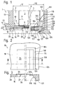
- FIGS. 1, 2, 3 1 and a conventional elevator system 101 each other juxtaposed.
- Both Figures 1 and 2 show one in one Elevator shaft 2,102 guided and not closer via one shown drive vertically over several floors of a Building's movable elevator car 3,103, which is in position here is shown on a floor stop.
- the Elevator car 3,103 is in both systems 1,101 with one conventional 4-leaf telescopic door 4,104 that opens centrally equipped, which on the shaft doors 5,105 facing Side on load-bearing elements of the elevator car structure is fixed and covers a cabin opening 6,106 or releases.
- the cabin door 4,104 includes one at the bottom with the elevator car 3,103 protruding threshold plate 7,107 Guide devices 8, 108 for therein by means of a Upper door operator and door operator Guide mechanism for horizontally sliding door leaves 9, 109.
- the free ends 10,110 of the threshold plate 7,107 are on both sides of the elevator car 3,103 on the side by one desired cabin opening dimension 6.106 dependent lateral Crossing route 11,111 into elevator shaft 2,102.
- the elevator shaft 2, 102 essentially has one to three Sides quadrangular cross-sectional area delimited by walls.
- the Shaft width 12.112 is due to the clear distance between two Side walls 13, 113 arranged parallel to one another are equal to that Length of the threshold plate 7.107 of the cabin door 3.103 plus side play 14,114 to wall 13,113.
- the fourth page is in the embodiment shown in Figure 1 by a Modular manhole wall 40 described in more detail below vertically stacked according to the invention Shaft wall modules 15 limited with integrated shaft doors.
- FIG. 1 shows one conventional design, in which a floor wall 116 the forms the fourth side of the elevator shaft 102.
- a door frame 115 in a shaft door opening the floor wall 116 anchored From one four-leaf telescopic shaft door assembly 105 is in there known way, a door frame 115 in a shaft door opening the floor wall 116 anchored. To do this, two are above a door fighter 117 interconnected vertical Door jamb 118 by means of several fastening anchors 117 in the Floor wall 116 and the two side posts 118 below connecting threshold plate 119 in a shaft-side Recess anchored to floor 120.
- the landing door assembly 105 is started from the threshold plate 109 set and in their position to floor 120 as well aligned with the elevator car 103.
- the Threshold plate 119 projects together with those guided therein Door leaves 121 of the shaft door 105 and their Movement mechanism in the shaft 102 and bridged the gap 122 between the floor 120 and the Cabin door 105.
- the threshold plate 119 and the The movement mechanism of the shaft door 105 is the same length as the threshold plate 107 and the door operator and Guiding mechanism of the elevator car door 104.
- the crossing route 123 of The landing door assembly 105 is equal to the width of the intended one Door leaves 121 and is through door jamb 118 and floor wall 116 covered next to the shaft door opening. With the doors open 104, 105 are the front edges of the door jambs 118, the door leaves 109,121 of the shaft 105 and cabin door 104 and des Cabin wall socket 124 aligned.
- the distance between Cabin door sill 7,107 and shaft door sill 17,117 each to be set very precisely in order to ensure secure coupling, i. H. on Interlocking door operator mechanism on the cabin 3,103 with the movement mechanism of the shaft doors 5,105 at Entry of the elevator car 3,103 into the floor stop for Unlock and move the shaft door leaves.
- shaft wall module 15 is according to the invention provided in a building Shaft door opening used. It covers the whole Shaft width 19 and protrudes into recesses 20 which in the lateral elevator shaft boundaries 13, 16, 21 are. After all, this is anchored in its installation position Manhole wall module 15 on its floor 21 facing Side clad with a facade 18.
- the recesses 20 are on the side of the Elevator shaft 2 in the floor wall 16 and in particular also consistently formed in floor 21 and result in the entire path of the elevator car 3 lateral Vertical grooves in the area between shaft side wall 13 and Floor facade 18.
- the depth 22 of the recess 20 corresponds to the depth of the Manhole wall module 15, the width of the shaft door sill plate 17 plus the constructive to align the shaft wall module 15 with integrated shaft doors 5 opposite the cabin 3 provided setting dimension. It also contains the door guide and Movement mechanism of the shaft doors 5 sufficient space.
- the lateral width 24 of the recess 20 is constructive predetermined dimension of the shaft door or cabin opening 6 generally by the width of the largest used Shaft door leaf 9.25 specified.
- Manhole wall module 15 built-in centrally opening 2-leaf Landing door 5 corresponds to the width of the two Door leaves 25 each at least half the width of the provided car door opening 6.
- FIG. 1 shows that formed by the shaft wall module 15 Floor wall 16 in accordance with the invention Depth savings 27 offset to the shaft 2.
- the frame covering 29 can be made of metal in Form of a fold of module 15 a few centimeters wide or also from the above-mentioned facade materials be executed.
- the looks a visually appealing version Use of refractive glass or transparent, optionally colored plastic materials before additionally from one or more discrete light sources Make the shaft door cut appear optically attractive.
- the shaft wall module 15 described in FIG. 1 is a how Built metal construction shown in Figure 4, in the two flat side assemblies 30 above via a lintel assembly 31 and connected to each other below via a connecting profile 32 are.
- Figure 4 shows side assemblies 30, each of which assemble from vertical square tubes 33, which on upper end over a double web 34, at the lower end over a Profile plate 35 and two at equal intervals between these arranged cross tubes 36 are interconnected.
- the length or height of the side assembly 30 corresponds at least the respective floor height, its width the intended width of the shaft wall wing to be displayed.
- the Lintel assembly 31 is in turn made of square tubes composite frame construction, the width of which is the measure of The shaft door opening corresponds and the height of the upper one Limits the shaft door opening forms.
- connection profile 32 is an L extruded profile on the at equal intervals the underside protruding sleeper support plates 37 for Attachment of the shaft door sill 17 are welded.
- suitable borehole pattern On formed in the double webs 34 and the lintel assembly 31 suitable borehole pattern provides a simple, accurate position Assembly of the movement mechanics of the shaft door leaves 9 safely.
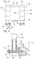
- FIG 5 is an enlarged partial section of the connection and Fastening point of two shaft wall modules 15 with for example, shown schematically in Figure 6 Floor-specific vertical force introduction 64 shown.
- the individual vertically stacked shaft wall modules 15 are each in the open end ends of the here vertical tubes 33 designed as square tubes inserted and axially displaceable sliding tube 38 aligned in the vertical direction to each other.
- At the frontal end of the Sliding tube 38 is perpendicular to the longitudinal axis of the tube right-angled mounting plate 41 laterally offset welded on.
- the mounting plate 41 lies flat on the Mounting plate 39 and is with this by means of a Screw 42 screwed and fixed in position. Accordingly, the mounting plate 41 is arranged below Manhole wall module 15 from below against the mounting plate 39 led and committed to it.
- Elongated holes 43 des Mounting plates 39 enable alignment in the x direction, while the mounting plate 39 on the building side End has elongated holes 44 with y orientation, the one corresponding alignment in the y direction, i.e. the distance of the allow modular shaft wall 40 to floor 21 before it is fixed by means of screw 45.
- Sliding tubes 38 and mounting plates 39 serve exclusively for adjustment in the x and y direction. Forces in z-direction / vertical direction are shown here as Sliding tube 38 shown linear guide none added.
- the vertical force introduction 64 or setting in z-direction takes place via an adjusting screw 46 on each lower end of the vertical tubes 33.
- the adjusting screw 46 is in a nut thread 47 of a fixedly attached angle 48 recorded and screwed in the z direction.
- the bolt end 50 the adjusting screw 46 is supported on the mounting plate 39 in the area of floor 21. That way when turning the adjusting screw 46, the shaft wall module 15 moved relative to the floor 21 in the z direction.
- the length of the sliding tube 38 can be the floor thickness be adjusted to align the alignment Shaft wall modules 15 to ensure each other.
- Independent of the guide path is the setting / adjustment range in the z direction by the thread length of the bolt 50 given.
- a lock nut 49 is used to secure the position.
- the modular shaft wall is at rest 40 self-supporting on a shaft pit module 51, which by means of integrated reference points 52 the exact position of the Shaft wall 40 specifies.
- the pit module 51 is independent of a self-supporting or floor-specific supported shaft wall design 40 z. B. as armored Precast concrete in the form of a tub delivered to the construction site and at the desired location in a prepared one Construction site pit sunk.
- the entire weight of the shaft wall rests 40 on the shaft pit module 51.
- the shaft wall 40 is thereby almost free-standing interface of the elevator system to the Building. As a connection are only on the floors anchored mounting plates provided.
- the threaded bolt 54 will supplemented in its function by a stacking direction the upper front end of the shaft wall module 56 protruding guide pin 59.
- the guide pin as Linear guidance in the z direction is accommodated in the lower one End 55 of the shaft wall module 15 placed thereon or the fastening device arranged there.
- the self-supporting construction of the shaft wall modules 15.56 offers the advantage that less overall and in particular too No fastening anchors are required on the floor walls become and therefore no more structure-borne noise from the Door mechanics and the door operator is transferred to the building.
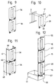
- the shaft wall modules 15, 56 are either complete pre-assembled, as in Figure 9, or, as in the example of the as far as built version 15 described, in the individual Assemblies brought to the construction site and then on site The latter is a subsequent integration the shaft door assembly 5 possible in a simple manner, like this is schematically illustrated in Figure 10.
- Shaft wall modules 15, 56 according to the invention are shown in FIG modular shaft wall 40 with each other and the so created Manhole wall 40 in total on support frame 60 to the Guide devices for the elevator car 63 or the Support pillars 61 of an autonomous, self-supporting elevator installation 62 pre-assembled into a complete elevator system.
- Manhole wall module 15 offers the possibility of that Shaft wall module 15 itself initially, i.e. without Landing door assembly 5, already during the shell construction phase in the to use the shaft opening provided on the building side and to fix.
- the shaft wall module already serves as Safety barrier. With the further expansion of the The shaft door assembly afterwards be installed while at the same time from the building side a facade builder the desired floor facade on the Manhole wall module installed.
- FIG. 12 schematically shows the known method for aligned alignment of the individual shaft wall modules 15, 56 one above the other and in the by the reference points 52 of the Pit module 51 given position using two Laser beams 65 from a laser cannon 66 or Laser adjustment device.
- the laser beams 65 give the desired bearing, along the one during assembly Shaft wall modules 15 arranged on each shaft wall module 15 Target plates 67 are aligned.
- Target plates 67 are aligned at shaft wall modules 15, 56 according to the invention exclusively in the middle of the end face 55 of each module 15, 56 provided Fastening points / fasteners on a convenient accessible point and about the amount of Shaft system the doors 5 corresponding to the laser beams 52 can be adjusted or aligned.
- the laser adjustment device 65, 66, 67 already on Shaft wall module 15.56 designed. If necessary, the laser cannon 66 can be multi-story Under certain circumstances, shaft systems can be used several times from the floors be implemented without causing unacceptable dimensional deviations is coming.
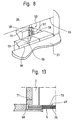
- Figure 13 shows an embodiment of the invention in which in addition to the version according to FIGS. 1, 2, 3
- the landing door 5 also has the elevator car door 49 in cutouts 68 can be moved into the side of the elevator shaft 2.
- the recess space corresponding to the construction volume of the door assemblies is in turn provided on the building side.
- the cabin door 69 and the shaft door 5 are as a centrally opening 2-wing door educated.
- the width of the individual door leaves can be 25.70 according to the invention can be chosen larger than previously. As a result can now use a significantly larger cabin access opening a less complex 2-wing door can be provided.
- Door sliding distance 71 also allows, usually on the side of the elevator car facing the shaft door 5 72, laterally delimiting the cabin access opening To waive cabin wall socket 124 (shown in dashed lines).
- the cabin access opening is through the cabin side walls 73 limited and the door leaves 70 are opened when the Cabin door 69 into one with the cabin side walls 73 aligned position laterally shifted.
- the shaft wall modules 76 consist of a profiled sheet steel with Shaft door opening 82 and bevelled side edges 79 Side edges 79 have the depth dimension of the therein integrated shaft door 5 and the cabin door running in it 69 corresponding expansion. On the building side, this is profiled Sheet steel clad by a desired facade 80. A Bend 81 forms over the circumference of the shaft door opening 82 a visually appealing panel on which the facade 80 ends at the front.
- Luminous elements 83 can also be used for advertising purposes Be shielded by transparent advertising media.
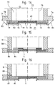
- FIGS. 15 and 16 Embodiments of the invention shown, in which the Manhole wall module 84, 85, as previously profiled in FIG. 14 Sheet steel with bevelled sides 86.87 is trained.
- the outer ends of the side edges are 86,87 again folded and preferably form u-shaped Side edges on both sides of the Schtwandmodule 84.85.
- U-shaped side edges are the shaft door assembly 5 and in particular the ends of the threshold plate 17 and the Door guidance and movement mechanism during transport to the construction site safely and well protected until installation embedded from damage.
- the fold 88 of the Side edges 86.87 acts as stiffening of the Shaft module structure and enables easy insulation of the Modules 84.85 towards the shaft side wall.
Landscapes
- Elevator Door Apparatuses (AREA)
Abstract
Description
Claims (19)
- Aufzugsanlage mit Schachttüren, welche in einer Schachttüröffnung eines über mehrere Stockwerke zumindest seitlich begrenzten Aufzugsschachts angeordnet sind, wobei die Schachttüre aus mindestens einem Türblatt besteht, welches über einen an einem aus zwei oben über ein Querelement und unten über ein Schwellenblech miteinander verbundene Seitenpfosten gebildeten Türrahmen festgelegten Bewegungsmechanismus im wesentlichen horizontal verschiebbar ist, dadurch gekennzeichnet, dass das Türblatt zumindest teilweise in der Schachtwand verschiebbar angeordnet ist und/ oder dass das Türblatt seitlich über die Schachtbreite hinaus verschiebbar ist.
- Aufzugsanlage mit Schachttüren nach Anspruch 1, dadurch gekennzeichnet, dass bisher im Schachtraum angeordnete Bauteile der Schachttürbaugruppe, wie das Schwellenblech, die Türblätter und deren Bewegungsmechanismus zumindest teilweise in der angrenzenden Stockwerkwand oder in Bauwerkbereiche, wie dem Eingangsbereich integriert sind.
- Aufzugsanlage mit Schachttüren nach Anspruch 1, dadurch gekennzeichnet, dass unabhängig vom Mass der Kabinenöffnung standardmässig eine Schachttüre mit einem entsprechend breiten Türblatt vorgesehen ist.
- Aufzugsanlage mit Schachttüren nach Anspruch 1, dadurch gekennzeichnet, dass die Kabinentüren über die Schachtbreite hinaus verschiebbar sind, wobei die seitlichen Schachtbegrenzungen entsprechende Aussparungen über die gesamte Hubstrecke der Aufzugskabine aufweisen
- Aufzugsanlage mit Schachttüren nach Anspruch 1, dadurch gekennzeichnet, dass der Türrahmen der Schachttürbaugruppe flächig ausgebildet ist.
- Aufzugsanlage mit Schachttüren nach Anspruch 5, dadurch gekennzeichnet, dass die Schachttürbaugruppe den Aufzugsschacht über die Schachtbreite hinaus zum Bauwerk hin abdeckt.
- Aufzugsanlage mit Schachttüren nach Anspruch 5, dadurch gekennzeichnet, dass die Schachtürbaugruppe zwischen den einzelnen Stockwerkböden eingesetzt und verankert ist.
- Aufzugsanlage mit Schachttüren nach Anspruch 1, dadurch gekennzeichnet, dass die Schachttürbaugruppe gleichzeitig als Schachtkonstruktion und als Befestigungskonstruktion für die Schachttüreinbauten dient.
- Aufzugsanlage mit Schachttüren nach Anspruch 5, dadurch gekennzeichnet, dass die Schachttürbaugruppe vormontiert, d. h. mit in den flächigen Türrahmen integrierten Schachttüreinbauten zur Baustelle verbringbar und als Schachtwandmodul montierbar ist.
- Aufzugsanlage mit Schachttüren nach Anspruch 9, dadurch gekennzeichnet, dass das Schachtwandmodul mit integrierter Schachttüre auf die an den Schacht angrenzende Stockwerkwand aufgesetzt ist.
- Aufzugsanlage mit Schachttüren nach Anspruch 10, dadurch gekennzeichnet, dass das Schachtwandmodul vollständig im Bereich des Stockwerkbodens vorgesehen ist.
- Aufzugsanlage mit Schachttüren nach Anspruch 9, dadurch gekennzeichnet, dass zwei oder mehr der Schachtwandmodule vertikal aufeinander angeordnet miteinander zu einer Schachtwand verbunden sind.
- Aufzugsanlage mit Schachttüren nach Anspruch 12, dadurch gekennzeichnet, dass die modular aufgebaute Schachtwand auf einem als Schacht- und/ Aufzugsfundament dienenden Schachtgrubenmodul ruht.
- Aufzugsanlage mit Schachttüren nach Anspruch 13, dadurch gekennzeichnet, dass das Schachtgrubenmodul Referenzpunkte aufweist, welche die exakte Position der modular aufgebauten Schachtwand vorgeben.
- Aufzugsanlage mit Schachttüren nach einem der Ansprüche 12 bis 14, dadurch gekennzeichnet, dass die modular aufgebaute Schachtwand als selbsttragende Konstruktion weitgehend unabhängig von der Bauwerk- oder Gebäudestruktur ausgebildet ist.
- Aufzugsanlage mit Schachttüren nach Anspruch 1, dadurch gekennzeichnet, dass die modulare Schachtwand pro Schachtwandmodul mittels zweier eindimensionaler Befestigungseinrichtungen mit dem jeweiligen Stockwerkboden verbunden ist.
- Aufzugsanlage mit Schachttüren nach Anspruch 16, dadurch gekennzeichnet, dass Befestigungselemente vorgesehen sind, die Gewichtskräfte der Schachtwandmodule auf den jeweiligen Etagenböden einleiten.
- Aufzugsanlage mit Schachttüren nach Anspruch 16, dadurch gekennzeichnet, dass die Befestigungseinrichtungen im mittleren Bereich der Schachttürausschnittsöffnung vorgesehen sind.
- Montageverfahren einer Aufzugsanlage mit Schachttüren nach Anspruch 1, dadurch gekennzeichnet, dass die Schachtwandmodule exakt lotrecht und fluchtend mittels einer Laserjustiereinrichtung auf dem Schachtgrubenmodul ausgerichtet werden.
Priority Applications (1)
| Application Number | Priority Date | Filing Date | Title |
|---|---|---|---|
| EP00114347A EP1069066B1 (de) | 1999-07-12 | 2000-07-05 | Aufzugsanlage mit Schachttüren |
Applications Claiming Priority (3)
| Application Number | Priority Date | Filing Date | Title |
|---|---|---|---|
| EP99810621 | 1999-07-12 | ||
| EP99810621 | 1999-07-12 | ||
| EP00114347A EP1069066B1 (de) | 1999-07-12 | 2000-07-05 | Aufzugsanlage mit Schachttüren |
Publications (2)
| Publication Number | Publication Date |
|---|---|
| EP1069066A1 true EP1069066A1 (de) | 2001-01-17 |
| EP1069066B1 EP1069066B1 (de) | 2005-11-09 |
Family
ID=8242918
Family Applications (1)
| Application Number | Title | Priority Date | Filing Date |
|---|---|---|---|
| EP00114347A Expired - Lifetime EP1069066B1 (de) | 1999-07-12 | 2000-07-05 | Aufzugsanlage mit Schachttüren |
Country Status (8)
| Country | Link |
|---|---|
| US (1) | US6540048B1 (de) |
| EP (1) | EP1069066B1 (de) |
| JP (1) | JP2001058783A (de) |
| AT (1) | ATE309170T1 (de) |
| BR (1) | BR0002715A (de) |
| CA (1) | CA2313737A1 (de) |
| DE (1) | DE50011543D1 (de) |
| ES (1) | ES2251914T3 (de) |
Cited By (5)
| Publication number | Priority date | Publication date | Assignee | Title |
|---|---|---|---|---|
| EP1449802A1 (de) * | 2003-02-24 | 2004-08-25 | Inventio Ag | Kombinierte Aufzugstüren |
| WO2007012913A1 (en) * | 2005-07-28 | 2007-02-01 | Otis Elevator Company | Elevator door with a set of landing doors and car doors with reduced thickness as a replacement for existing doors |
| ES2270695A1 (es) * | 2005-04-22 | 2007-04-01 | Jose Manuel Santos Lopez | Pozo prefabricado para ascensor. |
| EP2607284A1 (de) | 2011-12-21 | 2013-06-26 | Inventio AG | Aufzugsanlage mit einem Türsystem |
| DE102019220320A1 (de) * | 2019-12-20 | 2020-12-17 | Thyssenkrupp Elevator Innovation And Operations Ag | Ein Aufzugssystem |
Families Citing this family (16)
| Publication number | Priority date | Publication date | Assignee | Title |
|---|---|---|---|---|
| JP4527362B2 (ja) * | 2002-05-03 | 2010-08-18 | インベンテイオ・アクテイエンゲゼルシヤフト | エレベータ装置のシャフトドア監視方法 |
| WO2006011871A2 (en) * | 2004-06-28 | 2006-02-02 | Otis Elevator Company | Landing-mounted entrances that reduce total elevator installation time |
| EP1671917A1 (de) * | 2004-12-20 | 2006-06-21 | Inventio Ag | Aufzugsanlage mit Schachttüre und Türschliessvorrichtung |
| AU2010243848B2 (en) * | 2009-04-29 | 2016-09-29 | Inventio Ag | Marking device in elevator system |
| NL2005305C2 (nl) * | 2010-09-02 | 2012-03-05 | Reco Special Products B V | Liftinrichting, transportmiddel, werkwijze voor het positioneren en werkwijze voor het ter transport in gereedheid brengen. |
| US8800725B2 (en) * | 2011-01-05 | 2014-08-12 | Dominick J. Alois | Elevator liner apparatus and utilization method thereof |
| FI20116266A7 (fi) * | 2011-12-13 | 2013-06-14 | Kone Corp | Eristetty hissin tason ovi |
| US9850653B1 (en) | 2016-07-06 | 2017-12-26 | Par Systems, Inc. | Modular elevator shaft assembly and method for making the same |
| CN107651530B (zh) * | 2017-09-30 | 2023-08-01 | 东南电梯股份有限公司 | 升降机 |
| WO2019166685A1 (en) * | 2018-02-28 | 2019-09-06 | Kone Corporation | Elevator landing door assembly and its installation method |
| JP7159978B2 (ja) * | 2019-05-28 | 2022-10-25 | 三菱電機ビルソリューションズ株式会社 | エレベータの乗場ドアの位置調整工具、及びそれを用いた乗場ドアハンガーの交換方法 |
| CN110924630B (zh) * | 2019-12-05 | 2024-09-27 | 陈艳彬 | 一种带候梯厅一体化钢结构井道及其施工工艺 |
| CN116113591A (zh) * | 2020-07-09 | 2023-05-12 | 布利塞拉公司 | 观光真空电梯的井道力学 |
| CN114988249A (zh) * | 2021-03-01 | 2022-09-02 | 奥的斯电梯公司 | 对接机构、电梯井道模块及电梯系统 |
| AU2023295712A1 (en) * | 2022-06-14 | 2025-01-02 | Inventio Ag | Hoistway module for forming a hoistway composed of stacked hoistway modules for a lift installation |
| AU2024374076A1 (en) * | 2023-10-30 | 2026-05-14 | Inventio Ag | Lift shaft and method for attaching a lift element in a lift shaft |
Citations (5)
| Publication number | Priority date | Publication date | Assignee | Title |
|---|---|---|---|---|
| US3741351A (en) * | 1971-03-05 | 1973-06-26 | Westinghouse Electric Corp | Integrated elevator construction |
| FR2247415A1 (en) * | 1973-10-16 | 1975-05-09 | Konehissar Ab | Lift with two sets of sliding doors - has metal sheet between concrete shaft walls and front wall with doors in wall and cage |
| US4819403A (en) * | 1986-09-11 | 1989-04-11 | Otis Elevator Company | Method for installing elevator doors |
| EP0475074A1 (de) * | 1990-09-14 | 1992-03-18 | KONE Elevator GmbH | Verfahren für die Installierung von die Schachttüren eines Aufzugs |
| EP0606508A1 (de) * | 1993-01-14 | 1994-07-20 | Inventio Ag | Verfahren und Einrichtung für den Schachttüreinbau bei Aufzügen |
Family Cites Families (8)
| Publication number | Priority date | Publication date | Assignee | Title |
|---|---|---|---|---|
| US4122685A (en) * | 1977-03-29 | 1978-10-31 | St. Onge, Ruff & Associates, Inc. | Elevator shaft |
| CH649125A5 (fr) * | 1982-08-03 | 1985-04-30 | Inventio Ag | Huisserie de porte paliere d'ascenseur. |
| GB8806063D0 (en) * | 1988-03-15 | 1988-04-13 | New Domain Ltd | Improvements in/relating to lift shafts |
| US4896747A (en) * | 1988-07-28 | 1990-01-30 | Otis Elevator Company | Modular elevator system |
| FI92951C (fi) * | 1993-03-30 | 1995-01-25 | Kone Oy | Hissin tasonovi |
| JPH0812236A (ja) * | 1994-06-24 | 1996-01-16 | Mitsubishi Denki Bill Techno Service Kk | エレベータ乗場敷居 |
| US6145630A (en) * | 1996-01-25 | 2000-11-14 | Friedman; Harold S. | Sliding elevator-door assembly and method of installation |
| JPH10231065A (ja) * | 1997-02-21 | 1998-09-02 | Hitachi Ltd | エレベータの安全装置 |
-
2000
- 2000-06-27 JP JP2000192108A patent/JP2001058783A/ja not_active Withdrawn
- 2000-07-05 ES ES00114347T patent/ES2251914T3/es not_active Expired - Lifetime
- 2000-07-05 EP EP00114347A patent/EP1069066B1/de not_active Expired - Lifetime
- 2000-07-05 DE DE50011543T patent/DE50011543D1/de not_active Expired - Fee Related
- 2000-07-05 AT AT00114347T patent/ATE309170T1/de not_active IP Right Cessation
- 2000-07-07 CA CA002313737A patent/CA2313737A1/en not_active Abandoned
- 2000-07-11 BR BR0002715-4A patent/BR0002715A/pt not_active IP Right Cessation
- 2000-07-12 US US09/614,672 patent/US6540048B1/en not_active Expired - Fee Related
Patent Citations (5)
| Publication number | Priority date | Publication date | Assignee | Title |
|---|---|---|---|---|
| US3741351A (en) * | 1971-03-05 | 1973-06-26 | Westinghouse Electric Corp | Integrated elevator construction |
| FR2247415A1 (en) * | 1973-10-16 | 1975-05-09 | Konehissar Ab | Lift with two sets of sliding doors - has metal sheet between concrete shaft walls and front wall with doors in wall and cage |
| US4819403A (en) * | 1986-09-11 | 1989-04-11 | Otis Elevator Company | Method for installing elevator doors |
| EP0475074A1 (de) * | 1990-09-14 | 1992-03-18 | KONE Elevator GmbH | Verfahren für die Installierung von die Schachttüren eines Aufzugs |
| EP0606508A1 (de) * | 1993-01-14 | 1994-07-20 | Inventio Ag | Verfahren und Einrichtung für den Schachttüreinbau bei Aufzügen |
Cited By (6)
| Publication number | Priority date | Publication date | Assignee | Title |
|---|---|---|---|---|
| EP1449802A1 (de) * | 2003-02-24 | 2004-08-25 | Inventio Ag | Kombinierte Aufzugstüren |
| ES2270695A1 (es) * | 2005-04-22 | 2007-04-01 | Jose Manuel Santos Lopez | Pozo prefabricado para ascensor. |
| ES2270695B1 (es) * | 2005-04-22 | 2008-03-01 | Jose Manuel Santos Lopez | Pozo prefabricado para ascensor. |
| WO2007012913A1 (en) * | 2005-07-28 | 2007-02-01 | Otis Elevator Company | Elevator door with a set of landing doors and car doors with reduced thickness as a replacement for existing doors |
| EP2607284A1 (de) | 2011-12-21 | 2013-06-26 | Inventio AG | Aufzugsanlage mit einem Türsystem |
| DE102019220320A1 (de) * | 2019-12-20 | 2020-12-17 | Thyssenkrupp Elevator Innovation And Operations Ag | Ein Aufzugssystem |
Also Published As
| Publication number | Publication date |
|---|---|
| DE50011543D1 (de) | 2005-12-15 |
| ATE309170T1 (de) | 2005-11-15 |
| EP1069066B1 (de) | 2005-11-09 |
| BR0002715A (pt) | 2001-03-13 |
| JP2001058783A (ja) | 2001-03-06 |
| US6540048B1 (en) | 2003-04-01 |
| ES2251914T3 (es) | 2006-05-16 |
| CA2313737A1 (en) | 2001-01-12 |
Similar Documents
| Publication | Publication Date | Title |
|---|---|---|
| EP1069066B1 (de) | Aufzugsanlage mit Schachttüren | |
| EP3315448A2 (de) | Aufzugsanlage | |
| EP1108828A1 (de) | Aufzugschacht | |
| EP4536577B1 (de) | Aufzugssystem | |
| DE3714053C2 (de) | Aufzug für Personentransport | |
| DE19814639C2 (de) | Aufzugsanlage und Verfahren zu deren Anbindung an das Treppenhaus eines bestehenden, in Plattenbauweise hergestellten Gebäudes | |
| EP0579024A1 (de) | Fahrstuhlschacht für mehrgeschossige Fertighäuser | |
| EP2058456A1 (de) | Überdachung | |
| DE10210909B4 (de) | Fertigwandteil | |
| EP1321417A1 (de) | Aufzugsschacht und Verfahren zur Errichtung eines Aufzugsschachts | |
| DE4300823A1 (de) | Gelaender zur Befestigung an seitlichen Begrenzungswänden | |
| DE19907242B4 (de) | Mobile Trennwand mit Abschlußprofil | |
| DE20300662U1 (de) | Baukonstruktion zur nachträglichen Anbindung eines Außenaufzuges an ein Treppenhaus eines mehrgeschossigen Gebäudes | |
| DE69017299T2 (de) | Teleskopische Aufzugstüreinrichtung. | |
| EP0070962B1 (de) | Aus vorgefertigten Teilen bestehendes montierbares Gebäude | |
| DE2924444C2 (de) | Zarge für Fenster oder Türen, insbesondere für Kellerfenster | |
| EP3441557B1 (de) | Torvorrichtung mit einer türvorrichtung | |
| EP1321418A1 (de) | Aufzugsschacht | |
| AT410455B (de) | Holzbautafel und abschluss-profilelement hiefür | |
| EP0128294A2 (de) | Wandelement | |
| DE10132163A1 (de) | Aufzugstür-Anordnung | |
| DE3119692A1 (de) | Vorfertigbares bauelement | |
| AT403820B (de) | Balkon oder ähnlicher anbau sowie verfahren zur nachträglichen herstellung eines balkons oder ähnlichen anbaus | |
| DE102004034427A1 (de) | Holzhaus | |
| AT396953B (de) | Konstruktionselement für einen ständerbau |
Legal Events
| Date | Code | Title | Description |
|---|---|---|---|
| PUAI | Public reference made under article 153(3) epc to a published international application that has entered the european phase |
Free format text: ORIGINAL CODE: 0009012 |
|
| AK | Designated contracting states |
Kind code of ref document: A1 Designated state(s): AT BE CH CY DE DK ES FI FR GB GR IE IT LI LU MC NL PT SE |
|
| AX | Request for extension of the european patent |
Free format text: AL;LT;LV;MK;RO;SI |
|
| 17P | Request for examination filed |
Effective date: 20010618 |
|
| AKX | Designation fees paid |
Free format text: AT BE CH CY DE DK ES FI FR GB GR IE IT LI LU MC NL PT SE |
|
| 17Q | First examination report despatched |
Effective date: 20040526 |
|
| GRAP | Despatch of communication of intention to grant a patent |
Free format text: ORIGINAL CODE: EPIDOSNIGR1 |
|
| GRAS | Grant fee paid |
Free format text: ORIGINAL CODE: EPIDOSNIGR3 |
|
| GRAA | (expected) grant |
Free format text: ORIGINAL CODE: 0009210 |
|
| AK | Designated contracting states |
Kind code of ref document: B1 Designated state(s): AT BE CH CY DE DK ES FI FR GB GR IE IT LI LU MC NL PT SE |
|
| PG25 | Lapsed in a contracting state [announced via postgrant information from national office to epo] |
Ref country code: IE Free format text: LAPSE BECAUSE OF FAILURE TO SUBMIT A TRANSLATION OF THE DESCRIPTION OR TO PAY THE FEE WITHIN THE PRESCRIBED TIME-LIMIT Effective date: 20051109 |
|
| REG | Reference to a national code |
Ref country code: GB Ref legal event code: FG4D Free format text: NOT ENGLISH |
|
| REG | Reference to a national code |
Ref country code: CH Ref legal event code: EP |
|
| REG | Reference to a national code |
Ref country code: IE Ref legal event code: FG4D Free format text: LANGUAGE OF EP DOCUMENT: GERMAN |
|
| REF | Corresponds to: |
Ref document number: 50011543 Country of ref document: DE Date of ref document: 20051215 Kind code of ref document: P |
|
| GBT | Gb: translation of ep patent filed (gb section 77(6)(a)/1977) |
Effective date: 20060118 |
|
| PG25 | Lapsed in a contracting state [announced via postgrant information from national office to epo] |
Ref country code: GR Free format text: LAPSE BECAUSE OF FAILURE TO SUBMIT A TRANSLATION OF THE DESCRIPTION OR TO PAY THE FEE WITHIN THE PRESCRIBED TIME-LIMIT Effective date: 20060209 Ref country code: DK Free format text: LAPSE BECAUSE OF FAILURE TO SUBMIT A TRANSLATION OF THE DESCRIPTION OR TO PAY THE FEE WITHIN THE PRESCRIBED TIME-LIMIT Effective date: 20060209 Ref country code: SE Free format text: LAPSE BECAUSE OF FAILURE TO SUBMIT A TRANSLATION OF THE DESCRIPTION OR TO PAY THE FEE WITHIN THE PRESCRIBED TIME-LIMIT Effective date: 20060209 |
|
| REG | Reference to a national code |
Ref country code: ES Ref legal event code: FG2A Ref document number: 2251914 Country of ref document: ES Kind code of ref document: T3 |
|
| ET | Fr: translation filed | ||
| PGFP | Annual fee paid to national office [announced via postgrant information from national office to epo] |
Ref country code: PT Payment date: 20060621 Year of fee payment: 7 |
|
| REG | Reference to a national code |
Ref country code: IE Ref legal event code: FD4D |
|
| PGFP | Annual fee paid to national office [announced via postgrant information from national office to epo] |
Ref country code: FI Payment date: 20060713 Year of fee payment: 7 |
|
| PGFP | Annual fee paid to national office [announced via postgrant information from national office to epo] |
Ref country code: AT Payment date: 20060714 Year of fee payment: 7 Ref country code: DE Payment date: 20060714 Year of fee payment: 7 Ref country code: FR Payment date: 20060714 Year of fee payment: 7 Ref country code: NL Payment date: 20060714 Year of fee payment: 7 |
|
| PGFP | Annual fee paid to national office [announced via postgrant information from national office to epo] |
Ref country code: GB Payment date: 20060720 Year of fee payment: 7 |
|
| PGFP | Annual fee paid to national office [announced via postgrant information from national office to epo] |
Ref country code: ES Payment date: 20060728 Year of fee payment: 7 |
|
| PG25 | Lapsed in a contracting state [announced via postgrant information from national office to epo] |
Ref country code: MC Free format text: LAPSE BECAUSE OF NON-PAYMENT OF DUE FEES Effective date: 20060731 |
|
| PGFP | Annual fee paid to national office [announced via postgrant information from national office to epo] |
Ref country code: IT Payment date: 20060731 Year of fee payment: 7 |
|
| PGFP | Annual fee paid to national office [announced via postgrant information from national office to epo] |
Ref country code: BE Payment date: 20060822 Year of fee payment: 7 |
|
| PLBE | No opposition filed within time limit |
Free format text: ORIGINAL CODE: 0009261 |
|
| STAA | Information on the status of an ep patent application or granted ep patent |
Free format text: STATUS: NO OPPOSITION FILED WITHIN TIME LIMIT |
|
| 26N | No opposition filed |
Effective date: 20060810 |
|
| REG | Reference to a national code |
Ref country code: PT Ref legal event code: MM4A Free format text: LAPSE DUE TO NON-PAYMENT OF FEES Effective date: 20080107 |
|
| BERE | Be: lapsed |
Owner name: *INVENTIO A.G. Effective date: 20070731 |
|
| PGFP | Annual fee paid to national office [announced via postgrant information from national office to epo] |
Ref country code: CH Payment date: 20071015 Year of fee payment: 8 |
|
| GBPC | Gb: european patent ceased through non-payment of renewal fee |
Effective date: 20070705 |
|
| NLV4 | Nl: lapsed or anulled due to non-payment of the annual fee |
Effective date: 20080201 |
|
| PG25 | Lapsed in a contracting state [announced via postgrant information from national office to epo] |
Ref country code: NL Free format text: LAPSE BECAUSE OF NON-PAYMENT OF DUE FEES Effective date: 20080201 Ref country code: DE Free format text: LAPSE BECAUSE OF NON-PAYMENT OF DUE FEES Effective date: 20080201 |
|
| PG25 | Lapsed in a contracting state [announced via postgrant information from national office to epo] |
Ref country code: PT Free format text: LAPSE BECAUSE OF NON-PAYMENT OF DUE FEES Effective date: 20080107 Ref country code: FI Free format text: LAPSE BECAUSE OF NON-PAYMENT OF DUE FEES Effective date: 20070705 Ref country code: GB Free format text: LAPSE BECAUSE OF NON-PAYMENT OF DUE FEES Effective date: 20070705 |
|
| REG | Reference to a national code |
Ref country code: FR Ref legal event code: ST Effective date: 20080331 |
|
| PG25 | Lapsed in a contracting state [announced via postgrant information from national office to epo] |
Ref country code: AT Free format text: LAPSE BECAUSE OF NON-PAYMENT OF DUE FEES Effective date: 20070705 |
|
| PG25 | Lapsed in a contracting state [announced via postgrant information from national office to epo] |
Ref country code: LU Free format text: LAPSE BECAUSE OF NON-PAYMENT OF DUE FEES Effective date: 20060705 |
|
| PG25 | Lapsed in a contracting state [announced via postgrant information from national office to epo] |
Ref country code: BE Free format text: LAPSE BECAUSE OF NON-PAYMENT OF DUE FEES Effective date: 20070731 |
|
| PG25 | Lapsed in a contracting state [announced via postgrant information from national office to epo] |
Ref country code: FR Free format text: LAPSE BECAUSE OF NON-PAYMENT OF DUE FEES Effective date: 20070731 |
|
| REG | Reference to a national code |
Ref country code: ES Ref legal event code: FD2A Effective date: 20070706 |
|
| PG25 | Lapsed in a contracting state [announced via postgrant information from national office to epo] |
Ref country code: CY Free format text: LAPSE BECAUSE OF FAILURE TO SUBMIT A TRANSLATION OF THE DESCRIPTION OR TO PAY THE FEE WITHIN THE PRESCRIBED TIME-LIMIT Effective date: 20051109 |
|
| PG25 | Lapsed in a contracting state [announced via postgrant information from national office to epo] |
Ref country code: ES Free format text: LAPSE BECAUSE OF NON-PAYMENT OF DUE FEES Effective date: 20070706 |
|
| REG | Reference to a national code |
Ref country code: CH Ref legal event code: PL |
|
| PG25 | Lapsed in a contracting state [announced via postgrant information from national office to epo] |
Ref country code: LI Free format text: LAPSE BECAUSE OF NON-PAYMENT OF DUE FEES Effective date: 20080731 Ref country code: CH Free format text: LAPSE BECAUSE OF NON-PAYMENT OF DUE FEES Effective date: 20080731 |
|
| PG25 | Lapsed in a contracting state [announced via postgrant information from national office to epo] |
Ref country code: IT Free format text: LAPSE BECAUSE OF NON-PAYMENT OF DUE FEES Effective date: 20070705 |