EP1068839A2 - Dentalprothesen-Rohling - Google Patents
Dentalprothesen-Rohling Download PDFInfo
- Publication number
- EP1068839A2 EP1068839A2 EP00115104A EP00115104A EP1068839A2 EP 1068839 A2 EP1068839 A2 EP 1068839A2 EP 00115104 A EP00115104 A EP 00115104A EP 00115104 A EP00115104 A EP 00115104A EP 1068839 A2 EP1068839 A2 EP 1068839A2
- Authority
- EP
- European Patent Office
- Prior art keywords
- blank
- pin
- blank according
- axis
- dental prosthesis
- Prior art date
- Legal status (The legal status is an assumption and is not a legal conclusion. Google has not performed a legal analysis and makes no representation as to the accuracy of the status listed.)
- Withdrawn
Links
Images


Classifications
-
- A—HUMAN NECESSITIES
- A61—MEDICAL OR VETERINARY SCIENCE; HYGIENE
- A61C—DENTISTRY; APPARATUS OR METHODS FOR ORAL OR DENTAL HYGIENE
- A61C13/00—Dental prostheses; Making same
- A61C13/0003—Making bridge-work, inlays, implants or the like
-
- A—HUMAN NECESSITIES
- A61—MEDICAL OR VETERINARY SCIENCE; HYGIENE
- A61C—DENTISTRY; APPARATUS OR METHODS FOR ORAL OR DENTAL HYGIENE
- A61C13/00—Dental prostheses; Making same
- A61C13/0003—Making bridge-work, inlays, implants or the like
- A61C13/0022—Blanks or green, unfinished dental restoration parts
-
- Y—GENERAL TAGGING OF NEW TECHNOLOGICAL DEVELOPMENTS; GENERAL TAGGING OF CROSS-SECTIONAL TECHNOLOGIES SPANNING OVER SEVERAL SECTIONS OF THE IPC; TECHNICAL SUBJECTS COVERED BY FORMER USPC CROSS-REFERENCE ART COLLECTIONS [XRACs] AND DIGESTS
- Y10—TECHNICAL SUBJECTS COVERED BY FORMER USPC
- Y10T—TECHNICAL SUBJECTS COVERED BY FORMER US CLASSIFICATION
- Y10T428/00—Stock material or miscellaneous articles
- Y10T428/13—Hollow or container type article [e.g., tube, vase, etc.]
Definitions
- the invention relates to a dental prosthesis blank, the latter of which is not Machining end has a substantially cylindrical pin, and one Blank holding device with radially movable grippers for one Dental prosthesis blank.
- existing dental prosthesis blank usually has a cylindrical body, on which a mostly radially tapered cylindrical pin is formed. So from that Corpus the individual dental prosthesis can be worked out, the Blank during rotation in a blank holding device be clamped. After processing, the blank is made from the Removed holding device, the dental prosthesis still on a body stump appends.
- the invention is therefore based on the object, the post-processing with to simplify the dental prosthesis connected to the body-trunk of a blank.
- the pin has at least one reference element which, when the Pin in a blank holding device with a fixed Reference counter element precisely positioning the blank in the circumferential direction cooperates.
- the reference element and the reference counter element is a spatial reference system created, which in the blank holding device used blank always in a precisely determined Spatially determines the direction around the blank axis, so that the blank as often as you work the dental prosthesis out of the body the holding device can be inserted and removed from it without this changes the spatial position of the dental prosthesis.
- a Post-processing of the dental prosthesis is therefore with the required accuracy not difficult.
- the reference element is a plane Reference surface, which expediently extends parallel to the axis of the pin.
- a particularly expedient embodiment of the invention provides that the pin is axially slotted and the reference element is formed on or in the slot.
- the reference counter element can then be in the blank holding device trained free web or a rib that is transverse to the Extend the insertion direction of the pin into the holding device and a radial Width that exactly the distance between the two reference surfaces on the Corresponds to slotted cheeks.
- the one that connects the two reference surfaces can Slotted bottom serve as an axial reference, also with the web or the rib interacts when clamping the blank in the holding device.
- the circumferential direction is increased if the Pin is slotted crosswise, the respective cheeks of the cross slots are designed as plane, axially parallel reference surfaces.
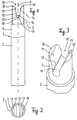
- the dental prosthesis blank 1 consists of a cylindrical body 2, the end not to be machined with a pin 3 coaxial to the body has cylindrical outer contour.
- Body 2 and pin 3 consist of here same material or from two materials with essentially the same hardness.
- the pin 3 is parallel to the axis 5 of the blank 1 from its free end provided with a straight slot 10 which extends transversely to the axis 5 and at which the axis 5 extends through its center.
- the slot 10 faces outwards curved, opposite surface sections 11, 13 on the as an insertion aid for a rod or rib-shaped reference counter-element 70 in the collet 90 serves.
- the Center of curvature 17 of the bulbous curved slot base 15 lies on the Axis 5 in the area of the reference surfaces 12, 14.
- the reference counter-element 70 consists of a cylindrical rod that extends transversely extends to the direction of insertion of the pin 3 into the opening of the collet 90.
- the collet has two in relation to the direction of insertion opposite bores in which the rod 70 on its two opposite ends is captured. Its outer diameter is the same mentioned distance of the reference surfaces 12, 14.
- the in the direction of the axis 5 taken widths of the reference surfaces 12, 14 and the innermost point 19 of the Slot bottom 15 are matched to each other so that the pin 3 in the opening the collet 90 can be inserted until the rod 70 laterally in Contact the reference surfaces 12, 14 and get to point 19.
- the pin 3 and thus the dental prosthesis blank is thus in the collet 90 clearly defined in the circumferential direction and in the axial direction.
- This Definition is, for example, when reworking the blank with a Repeatable accuracy of about 30 ⁇ , i.e. Deviations from the target position of the blank when the pin 3 is reinserted into the collet 90 not greater than the stated value. Otherwise, the collet 90 on her not shown end may be provided with an external thread, for example that they are in the feed of a processing machine, not shown, for the blank can be turned.
- the jacket of the pin 30 is cylindrical, the result of the outside curved insertion surfaces 41, 43 each have four separate posts 45, 47, 65, 67, which taper to the outside.
- FIGS. 7 to 10 The embodiment of the invention shown in FIGS. 7 to 10 comes especially when the material of the body 2 is less hard has that of the pin 3.
- the body 2 is on one with the Pin 73 provided holder 80 glued or welded on the end face.
- To the holder 80 has an end circular pan 75 with an outer circumferential raised edge 77 around the bottom 79, in which the body 2 is inserted can be.
- the clear width enclosed by the edge is only slightly larger than the outer diameter of the body to be inserted, here cylindrical.
- the Pin 73 corresponds in all details to pin 3, so it is in particular with the reference surfaces described there.
- Figure 9 is one of these Recognize reference areas at 72.
- the holder 82 according to FIG. 10 differs from the holder 80 only in that the edge in four edge segments 83, 84, 86 equally spaced in the circumferential direction, 88 is divided so that it has a square area with the bottom 89 enclose in which a body with a corresponding square Cross section on the floor 89 between the edge segments 83, 84, 86, 88 can be used and glued there.
Abstract
Description
- Fig. 1
- eine Seitenansicht eines mit den Merkmalen der Erfindung ausgerüsteten Dentalprothesen-Rohlings in einer ersten Ausführungsform;
- Fig. 2
- eine Draufsicht auf den Zapfen des Rohlings nach Fig. 1;
- Fig. 3
- eine schematische perspektivische Darstellung des Zapfens nach Fig. 1 und 2
- Fig. 4
- eine Seitenansicht einer zweiten Ausführungsform eines erfindungsgemäßen Dentalprothesen-Rohlings;
- Fig. 5
- eine Draufsicht auf den Zapfen des Rohlings nach Fig. 4;
- Fig. 6
- eine schematische perspektivische Darstellung des Zapfens aus dem Rohling nach Fig. 4 und 5;
- Fig. 7
- eine Stirnansicht eines einen Zapfen aufweisenden Halters für einen Dentalprothesen-Rohling;
- Fig. 8
- einen Axialschnitt durch den Halter nach Fig. 7 längs der Linie A-A;
- Fig. 9
- eine perspektivische Ansicht des Halters nach Fig. 7;
- Fig. 10
- eine perspektivische Ansicht eines Halters für einen im Querschnitt quadratischen Dentalprothesen-Rohling;
- Fig. 11
- eine Seitenansicht des Kopfes einer Spannzange und
- Fig. 12
- eine Stirnansicht der Spannzange nach Fig. 11.
Claims (15)
- Dentalprothesen-Rohling, dessen nicht zu bearbeitendes Ende mit einem im wesentlichen zylindrischen Zapfen verbunden ist, dadurch gekennzeichnet, daß der Zapfen (3; 30; 73) wenigstens ein Referenzelement (12, 14; 44, 49, 51, 62, 64; 72) aufweist, welches beim Einspannen des Zapfens in eine Rohling-Haltevorrichtung (90) mit einem Referenzgegenelement (70), den Rohling (1; 20) in Umfangsrichtung positionierend, zusammenwirkt.
- Rohling nach Anspruch 1, dadurch gekennzeichnet, daß der Zapfen und der Rohling aus einem Teil bestehen.
- Rohling nach Anspruch 1 oder 2, dadurch gekennzeichnet, daß der Zapfen (73) Teil eines Halters (80; 82) mit einer Rohling-Aufnahme (75) ist.
- Rohling nach einem der vorstehenden Ansprüche, dadurch gekennzeichnet, daß das Referenzelement eine plane Referenzfläche ist.
- Rohling nach Anspruch 4, dadurch gekennzeichnet, daß sich die Referenzfläche parallel zur Achse (5; 50) des Zapfens erstreckt.
- Rohling nach einem der vorstehenden Ansprüche, dadurch gekennzeichnet, daß der Zapfen axial geschlitzt ist und das Referenzelement am oder im Schlitz (10; 40,60) ausgebildet ist.
- Rohling nach Anspruch 6, dadurch gekennzeichnet, daß im Schlitz bezüglich der Achse (5; 50) des Rohlings symmetrisch gegenüberliegende achsparallele plane Referenzflächen ausgebildet sind, die einen vorgegebenen, der Stärke des Referenzgegenelementes (70) entsprechenden Abstand haben.
- Rohling nach einem der Ansprüche 6 oder 7, dadurch gekennzeichnet, daß der Krümmungsmittelpunkt (17) des bauchigen Schlitzbodens (15) auf der Achse (5) und zwischen den Referenzflächen (12, 14) liegt.
- Rohling nach einem der Ansprüche 6 bis 8, dadurch gekennzeichnet, daß der innerste Punkt (19) des Schlitzes die axiale Positionierung des Zapfens bestimmt.
- Rohling nach einem der vorstehenden Ansprüche, dadurch gekennzeichnet, daß in den Zapfen (30) zwei quer zur Achse (50) des Rohlings (20) liegende Schlitze (40, 60) eingeschnitten sind.
- Rohling nach Anspruch 10, dadurch gekennzeichnet, daß die beiden Schlitze (40, 60) quer zueinander liegen.
- Rohling nach Anspruch 10 oder 11, dadurch gekennzeichnet, daß in jedem der beiden Schlitze gegenüberliegende Referenzflächen ausgebildet sind.
- Rohling-Haltevorrichtung mit radial beweglichen Greifern für einen Dentalprothesen-Rohling nach einem der vorstehenden Ansprüche, dadurch gekennzeichnet, daß wenigstens ein Referenzgegenelement (70) beim Einspannen des Zapfens mit einem am Zapfen ausgebildeten Referenzelement, den Rohling in Umfangsrichtung eindeutig positionierend, zusammenwirkt.
- Vorrichtung nach Anspruch 13, dadurch gekennzeichnet, daß das Referenzgegenelement einen sich quer zur Mittellinie einer Spannzange (90) erstreckenden Stab aufweist, dessen Stärke gleich dem Abstand von Referenzflächen im geschlitzten Zapfen ist.
- Vorrichtung nach Anspruch 14, dadurch gekennzeichnet, daß der Stab die axiale Position des eingespannten Rohlings mit Zapfen definiert.
Applications Claiming Priority (2)
| Application Number | Priority Date | Filing Date | Title |
|---|---|---|---|
| DE19932877A DE19932877B4 (de) | 1999-07-16 | 1999-07-16 | Dentalprothesen-Rohling |
| DE19932877 | 1999-07-16 |
Publications (2)
| Publication Number | Publication Date |
|---|---|
| EP1068839A2 true EP1068839A2 (de) | 2001-01-17 |
| EP1068839A3 EP1068839A3 (de) | 2002-12-18 |
Family
ID=7914733
Family Applications (1)
| Application Number | Title | Priority Date | Filing Date |
|---|---|---|---|
| EP00115104A Withdrawn EP1068839A3 (de) | 1999-07-16 | 2000-07-12 | Dentalprothesen-Rohling |
Country Status (4)
| Country | Link |
|---|---|
| US (1) | US6660400B1 (de) |
| EP (1) | EP1068839A3 (de) |
| JP (1) | JP2001046402A (de) |
| DE (1) | DE19932877B4 (de) |
Cited By (6)
| Publication number | Priority date | Publication date | Assignee | Title |
|---|---|---|---|---|
| EP2286759A2 (de) | 2009-08-20 | 2011-02-23 | Ivoclar Vivadent AG | Halter für CAD/CAM-Rohlinge |
| WO2011029615A1 (de) * | 2009-09-11 | 2011-03-17 | Enta Holding B.V. | Zahnblock zur fertigung von zahnersatz mit daran befestigtem halter |
| EP2246008A3 (de) * | 2009-05-02 | 2011-06-29 | White Peaks Dental Systems GmbH & Co. KG | Verfahren zur Herstellung von künstlichem Zahnersatz |
| WO2016079282A1 (de) * | 2014-11-21 | 2016-05-26 | Merz Dental Gmbh | Verfahren zur lagepositionierung eines halbzeuges, verfahren zur herstellung eines halbzeuges zur reproduzierbaren lagepositionierung sowie ein geeignetes halbzeug und eine entsprechende verwendung hierfür |
| EP3047818A1 (de) * | 2015-01-21 | 2016-07-27 | STEGER, Heinrich | Haltevorrichtung für ein dentales werkstück |
| RU2769884C1 (ru) * | 2018-12-25 | 2022-04-07 | Токуяма Дентал Корпорейшн | Соединительная конструкция для обработки |
Families Citing this family (21)
| Publication number | Priority date | Publication date | Assignee | Title |
|---|---|---|---|---|
| SE522958C2 (sv) | 2000-12-29 | 2004-03-16 | Nobel Biocare Ab | Förfarande, arrangemang (anordning) och program vid eller för protetisk installation |
| SE520765C2 (sv) * | 2001-12-28 | 2003-08-19 | Nobel Biocare Ab | Anordning och arrangemang för att medelst mall ta upp hål till implantat i ben, företrädesvis käkben |
| US7534213B2 (en) * | 2002-09-09 | 2009-05-19 | Kneebourne Therapeutic, Llc | Knee extension treatment apparatus |
| SE526665C2 (sv) * | 2002-12-30 | 2005-10-25 | Nobel Biocare Ab | Anordning vid dentalt fastskruvningsarrangemang |
| SE526666C2 (sv) * | 2002-12-30 | 2005-10-25 | Nobel Biocare Ab | Anordning och arrangemang för fixturinstallation |
| DE10322762B4 (de) * | 2003-05-19 | 2013-12-05 | Sirona Dental Systems Gmbh | Halter für einen Rohling und Verfahren zur Vermessung der Lage und Orientierung des Halters |
| DE102004020369A1 (de) * | 2004-04-23 | 2005-11-17 | Sirona Dental Systems Gmbh | Verfahren zur Herstellung eines dentalen Passkörpers |
| SE527503C2 (sv) * | 2004-08-05 | 2006-03-21 | Nobel Biocare Ab | Anordning och förfarande för att underlätta applicering till rätt läge av tand- eller tandrestmall |
| US20060172263A1 (en) * | 2005-02-01 | 2006-08-03 | D4D Technologies, Lp | Mill blank |
| WO2007129955A1 (en) | 2006-05-04 | 2007-11-15 | Nobel Biocare Services Ag | A device for securing a dental implant in bone tissue, a method for making a surgical template and a method of securing a dental implant in bone tissue |
| CA2674060C (en) | 2006-12-28 | 2016-05-03 | Russell A. Giordano | Multicolor dental blanks and related methods |
| EP2101678B1 (de) | 2007-01-10 | 2019-05-08 | Nobel Biocare Services AG | Verfahren und system für dentalplanung und produktion |
| US8551622B2 (en) * | 2007-07-20 | 2013-10-08 | Ivoclar Vivadent Ag | Addressable matrices/cluster blanks for dental CAD/CAM systems and optimization thereof |
| US8568897B2 (en) * | 2007-07-20 | 2013-10-29 | Ivoclar Vivadent Ag | Addressable matrices/cluster blanks for dental CAD/CAM systems and optimization thereof |
| DE102007043837B4 (de) * | 2007-09-14 | 2014-02-13 | Ivoclar Vivadent Ag | Rohlinganordnung |
| US8443502B2 (en) * | 2007-09-14 | 2013-05-21 | Ivoclar Vivadent Ag | Blank arrangement |
| EP2254068B1 (de) | 2009-05-18 | 2020-08-19 | Nobel Biocare Services AG | Verfahren und System, die einen verbesserten Datenabgleich zur virtuellen Planung bereitstellen |
| CN104168853A (zh) * | 2012-02-29 | 2014-11-26 | 义获嘉伟瓦登特公司 | 用于制造牙科修补物的坯件 |
| DE102012020519A1 (de) * | 2012-10-19 | 2014-04-24 | Eve Ernst Vetter Gmbh | Vorrichtung zum Halten eines Zahnersatzteils |
| USD736389S1 (en) * | 2013-05-14 | 2015-08-11 | Ivoclar Vivadent Ag | Milling blank |
| US10010386B2 (en) | 2015-03-24 | 2018-07-03 | Ivoclar Vivadent Ag | Dental blank holder |
Citations (1)
| Publication number | Priority date | Publication date | Assignee | Title |
|---|---|---|---|---|
| EP0759728A1 (de) | 1994-05-05 | 1997-03-05 | Joseph Hintersehr | Verfahren und vorrichtung zur herstellung einer dentalprothese |
Family Cites Families (8)
| Publication number | Priority date | Publication date | Assignee | Title |
|---|---|---|---|---|
| DE3312908C2 (de) * | 1982-06-16 | 1986-11-20 | Gäßler GmbH & Co KG, 7900 Ulm | Anordnung zur lösbaren Befestigung einer Zahnprothese und Verfahren zu ihrer Herstellung |
| CH665551A5 (de) * | 1984-03-06 | 1988-05-31 | Werner Hans Dr Med De Moermann | Rohling zur herstellung zahntechnischer formteile. |
| DE59106910D1 (de) * | 1990-10-10 | 1995-12-21 | Mikrona Technologie Ag | Rohling zur Herstellung eines zahntechnischen Formteils und Haltevorrichtung für denselben. |
| US5362237A (en) * | 1991-08-02 | 1994-11-08 | Wellesley Research Associates, Inc. | Dental post construction |
| ATE281126T1 (de) * | 1996-05-17 | 2004-11-15 | Brandestini Marco | Verfahren zur herstellung dentaler rekonstruktionen und rohling zur durchführung des verfahrens |
| DE19733161C2 (de) * | 1997-07-31 | 2000-09-07 | Megadenta Gmbh Dentalprodukte | Halter und Vorrichtung zum Befestigen eines Formkörpers |
| EP1039840A4 (de) * | 1997-12-10 | 2006-10-04 | Debbie Llc | Zahnmedizinisches implantatsystem und verfahren |
| US6482284B1 (en) * | 2000-08-31 | 2002-11-19 | 3M Innovative Properties Company | Method of making a dental mill blank and support stub assembly |
-
1999
- 1999-07-16 DE DE19932877A patent/DE19932877B4/de not_active Revoked
-
2000
- 2000-07-12 EP EP00115104A patent/EP1068839A3/de not_active Withdrawn
- 2000-07-14 JP JP2000214330A patent/JP2001046402A/ja active Pending
- 2000-07-17 US US09/618,146 patent/US6660400B1/en not_active Expired - Fee Related
Patent Citations (1)
| Publication number | Priority date | Publication date | Assignee | Title |
|---|---|---|---|---|
| EP0759728A1 (de) | 1994-05-05 | 1997-03-05 | Joseph Hintersehr | Verfahren und vorrichtung zur herstellung einer dentalprothese |
Cited By (8)
| Publication number | Priority date | Publication date | Assignee | Title |
|---|---|---|---|---|
| EP2246008A3 (de) * | 2009-05-02 | 2011-06-29 | White Peaks Dental Systems GmbH & Co. KG | Verfahren zur Herstellung von künstlichem Zahnersatz |
| EP2286759A2 (de) | 2009-08-20 | 2011-02-23 | Ivoclar Vivadent AG | Halter für CAD/CAM-Rohlinge |
| WO2011029615A1 (de) * | 2009-09-11 | 2011-03-17 | Enta Holding B.V. | Zahnblock zur fertigung von zahnersatz mit daran befestigtem halter |
| WO2016079282A1 (de) * | 2014-11-21 | 2016-05-26 | Merz Dental Gmbh | Verfahren zur lagepositionierung eines halbzeuges, verfahren zur herstellung eines halbzeuges zur reproduzierbaren lagepositionierung sowie ein geeignetes halbzeug und eine entsprechende verwendung hierfür |
| US10993790B2 (en) | 2014-11-21 | 2021-05-04 | Merz Dental Gmbh | Method for positioning a semifinished product, method for producing a semifinished product for reproducible positioning, and suitable semifinished product and corresponding use thereof |
| EP3047818A1 (de) * | 2015-01-21 | 2016-07-27 | STEGER, Heinrich | Haltevorrichtung für ein dentales werkstück |
| US10213841B2 (en) | 2015-01-21 | 2019-02-26 | Heinrich Steger | Holding apparatus for a dental workpiece |
| RU2769884C1 (ru) * | 2018-12-25 | 2022-04-07 | Токуяма Дентал Корпорейшн | Соединительная конструкция для обработки |
Also Published As
| Publication number | Publication date |
|---|---|
| DE19932877A1 (de) | 2001-01-25 |
| DE19932877B4 (de) | 2006-10-26 |
| JP2001046402A (ja) | 2001-02-20 |
| EP1068839A3 (de) | 2002-12-18 |
| US6660400B1 (en) | 2003-12-09 |
Similar Documents
| Publication | Publication Date | Title |
|---|---|---|
| EP1068839A2 (de) | Dentalprothesen-Rohling | |
| EP1616645B1 (de) | Wendeschneideinsatz zum Drehen | |
| DE4444241C2 (de) | Spannvorrichtung | |
| EP3047818B1 (de) | Haltevorrichtung für ein dentales werkstück | |
| EP0255042A1 (de) | Spannvorrichtung für ein Werkzeug an einer Werkzeugmaschine, insbesondere einer Senkerodiermaschine | |
| DE3432050C2 (de) | ||
| EP1136158A1 (de) | Schneidplattenhalter für Drehwerkzeuge sowie Stechplatten hierfür | |
| DE2744410A1 (de) | 4-backen-spannfutter fuer ein werkstueck | |
| EP3463724A1 (de) | Schneidplatte und werkzeug zur spanenden bearbeitung | |
| EP3909477A1 (de) | Vorhangaufhänger | |
| EP0523404B1 (de) | Zweischneidiges Gesenkwerkzeug zum Fräsen und Bohren | |
| DE69923362T2 (de) | Werkzeug zur spanabhebenden Bearbeitung | |
| DE4339271C1 (de) | Haltevorrichtung zur lösbaren Halterung zu bearbeitender Werkstücke | |
| EP0144073B1 (de) | Schneidwerkzeug | |
| EP1049555B1 (de) | Spannzange zum halten von stangenmaterial in drehmaschinen | |
| EP3463731B1 (de) | Schneidplatte für ein fräswerkzeug und fräswerkzeug | |
| DE3530745A1 (de) | Messerkopf | |
| DE2112092A1 (de) | Werkzeughalter | |
| DE102018107453B4 (de) | Wälzfräsvorrichtung | |
| DE102019128697A1 (de) | Drehwerkzeug | |
| DE3511580C2 (de) | ||
| DE2628624A1 (de) | Fraeswerkzeug | |
| DE19500946C1 (de) | Winkelverstellbarer Werkstücksitz | |
| DE2462340C3 (de) | Messerhalter zum Einsetzen in Tragscheiben eines Messerkopfes | |
| DE102021122424A1 (de) | Werkzeug zur spanenden Bearbeitung, Schneideinsatz-Halter und Schneideinsatz |
Legal Events
| Date | Code | Title | Description |
|---|---|---|---|
| PUAI | Public reference made under article 153(3) epc to a published international application that has entered the european phase |
Free format text: ORIGINAL CODE: 0009012 |
|
| AK | Designated contracting states |
Kind code of ref document: A2 Designated state(s): AT BE CH CY DE DK ES FI FR GB GR IE IT LI LU MC NL PT SE |
|
| AX | Request for extension of the european patent |
Free format text: AL;LT;LV;MK;RO;SI |
|
| PUAL | Search report despatched |
Free format text: ORIGINAL CODE: 0009013 |
|
| AK | Designated contracting states |
Kind code of ref document: A3 Designated state(s): AT BE CH CY DE DK ES FI FR GB GR IE IT LI LU MC NL PT SE |
|
| AX | Request for extension of the european patent |
Free format text: AL;LT;LV;MK;RO;SI |
|
| 17P | Request for examination filed |
Effective date: 20021219 |
|
| AKX | Designation fees paid |
Designated state(s): AT CH DE FR LI SE |
|
| STAA | Information on the status of an ep patent application or granted ep patent |
Free format text: STATUS: THE APPLICATION IS DEEMED TO BE WITHDRAWN |
|
| 18D | Application deemed to be withdrawn |
Effective date: 20060120 |