EP1066938B1 - Vorrichtung zum Granulieren von Kunststoffsträngen - Google Patents
Vorrichtung zum Granulieren von Kunststoffsträngen Download PDFInfo
- Publication number
- EP1066938B1 EP1066938B1 EP00114029A EP00114029A EP1066938B1 EP 1066938 B1 EP1066938 B1 EP 1066938B1 EP 00114029 A EP00114029 A EP 00114029A EP 00114029 A EP00114029 A EP 00114029A EP 1066938 B1 EP1066938 B1 EP 1066938B1
- Authority
- EP
- European Patent Office
- Prior art keywords
- strands
- running
- granulator
- rest
- air
- Prior art date
- Legal status (The legal status is an assumption and is not a legal conclusion. Google has not performed a legal analysis and makes no representation as to the accuracy of the status listed.)
- Expired - Lifetime
Links
- 238000001816 cooling Methods 0.000 claims description 4
- 238000011144 upstream manufacturing Methods 0.000 claims description 2
- 239000002826 coolant Substances 0.000 claims 1
- 238000005453 pelletization Methods 0.000 claims 1
- 229920000642 polymer Polymers 0.000 claims 1
- 238000006073 displacement reaction Methods 0.000 description 3
- 230000000694 effects Effects 0.000 description 3
- 230000002349 favourable effect Effects 0.000 description 3
- 239000008187 granular material Substances 0.000 description 3
- 230000015572 biosynthetic process Effects 0.000 description 2
- 239000000498 cooling water Substances 0.000 description 2
- 230000004048 modification Effects 0.000 description 2
- 238000012986 modification Methods 0.000 description 2
- 239000000853 adhesive Substances 0.000 description 1
- 230000001070 adhesive effect Effects 0.000 description 1
- 238000004140 cleaning Methods 0.000 description 1
- 230000006835 compression Effects 0.000 description 1
- 238000007906 compression Methods 0.000 description 1
- 238000011109 contamination Methods 0.000 description 1
- 239000000110 cooling liquid Substances 0.000 description 1
- 230000005484 gravity Effects 0.000 description 1
- 230000003116 impacting effect Effects 0.000 description 1
- 239000000463 material Substances 0.000 description 1
- 239000012768 molten material Substances 0.000 description 1
- 230000001737 promoting effect Effects 0.000 description 1
- 230000008439 repair process Effects 0.000 description 1
- XLYOFNOQVPJJNP-UHFFFAOYSA-N water Substances O XLYOFNOQVPJJNP-UHFFFAOYSA-N 0.000 description 1
Images




Classifications
-
- B—PERFORMING OPERATIONS; TRANSPORTING
- B65—CONVEYING; PACKING; STORING; HANDLING THIN OR FILAMENTARY MATERIAL
- B65H—HANDLING THIN OR FILAMENTARY MATERIAL, e.g. SHEETS, WEBS, CABLES
- B65H51/00—Forwarding filamentary material
- B65H51/16—Devices for entraining material by flow of liquids or gases, e.g. air-blast devices
-
- B—PERFORMING OPERATIONS; TRANSPORTING
- B29—WORKING OF PLASTICS; WORKING OF SUBSTANCES IN A PLASTIC STATE IN GENERAL
- B29B—PREPARATION OR PRETREATMENT OF THE MATERIAL TO BE SHAPED; MAKING GRANULES OR PREFORMS; RECOVERY OF PLASTICS OR OTHER CONSTITUENTS OF WASTE MATERIAL CONTAINING PLASTICS
- B29B9/00—Making granules
- B29B9/02—Making granules by dividing preformed material
- B29B9/06—Making granules by dividing preformed material in the form of filamentary material, e.g. combined with extrusion
Definitions
- the invention relates to a device for granulating molten material out of nozzles emerging strands of plastic with a granulator, at the one between the nozzles and the granulator a cooling liquid flow leading cooling section and a drainage section are provided.
- Such a device is known from DE OS 197 28 661.
- This device results the problem of a safe guidance of the strands at the end of the drainage route to the entrance of the granulator, especially if in the drainage section a revolving conveyor belt is provided. This is especially pronounced Problem if it remains soft even in the final state of the strands Materials is. When doing the transport of the strands only due a push, then the strands tend to meander, which then increases leads irregularly cut granules.
- the invention is based on the object, the leadership of the strands in the area to improve before the granulator. According to the invention, this is done by that the granulator an adjoining the drainage section inlet support upstream, with at least one transverse to the direction of the strands arranged as a step with vertical downward level difference in the inlet support formed air nozzle assembly for generating a the step substantially parallel to the direction of the strands emerging Air flow is provided, which entrains the inlet support supplied strands.
- the air nozzle assembly in the stage can be useful as a slot form. This then extends across the width of the inlet support. It is but also possible, the air nozzle assembly as a series of in the stage arranged side by side arranged individual nozzles to make something out production-technical reasons for the formation of the stage is favorable. Furthermore results from the choice of a favorable diameter of the nozzle one particularly high flow velocity for the air flow.
- the inlet support can be removed between the drainage section and make the granulator. In this case results in decrease of the Inlet support a free space between drainage section and granulator and thus a particularly good accessibility of the granulator, which in particular at Repairs or cleaning of the granulator is an advantage.
- the decrease of the inlet support can be designed differently. That's the way it is possible to arrange the inlet support swing out. You can do that But it can also be pushed out.
- Fig. 1 the apparatus for granulating molten matter is here not shown nozzles emerging strands 1 made of plastic in the scope as required for the understanding of the invention. Shown is the end of the following on the also not shown cooling section Enticass mecanicssort 2, in which the strands 1 of the circulating conveyor belt 3rd be carried and transported, wherein the conveyor belt 3 of the driven Deflection roller 4 is moved. In that regard, it is state of the art.
- the inlet support 5 connects to the be pushed through the moving conveyor belt 3, the strands 1.
- the Inlet pad 5 has between the two walls 6 and 7 (the latter is canceled drawn) on the two stages 8 and 9, to which the Support surfaces 10, 11 and 12 forward or rearrange. This is enough Support surface 10 close to the conveyor belt 3 zoom, so that the conveyor belt 3 feed strands 1 are pushed securely onto the support surface 10.
- the stage 8 is used to form the slot 13, which extends across the inlet pad 5 extends. Accordingly, in the stage 9, the slot nozzle 14th formed, which also extends across the inlet support 5.
- this Slot nozzles is pressurized via the tubular air connection 15 Air supplied (see indicated arrow 16), so that from the slot nozzles 13th or 14 a through the four adjacent short arrows indicated airflow emerges on the on the support surfaces 11 and 12 Overlying strands 1 acts and this entrains, so that the further promotion the strands 1 is ensured even in the region of the inlet support 5.
- Air supplied see indicated arrow 16
- Overlying strands 1 acts and this entrains, so that the further promotion the strands 1 is ensured even in the region of the inlet support 5.
- the granulator 17 contains, as is known, the two feed rollers 18 and 19, which leave a nip open between them, into which the inlet 20 of the Granulator 17 protrudes.
- FIG. 2 is a schematic representation of the arrangement according to FIG. 1 shown in section. According to this sectional view, the bridge bridges Inlet pad 5 the area between the end of the drainage section 2 and the entrance of the granulator 17, whereby a certain distance between the Granulator 17 and the end of the drainage section 2 results, by Decrease in the inlet support 5 easy accessibility of the entrance of the Granulator 17 results, so that e.g. in case of contamination or jamming and the like operators conveniently on the accessible granulator 17 can handle.
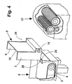
- Figure 2 shows as well as Figure 1 a hinge assembly with the axis 24 and the Hinge arms 25 and 26, which is a folding up of the inlet support. 5 allow, as shown in connection with Figure 4.
- FIG 5 is a structurally different design movement of the inlet support 5 for making available the entrance of the granulator 17 is shown and that by means of a device for transverse displacement of the inlet support 5.
- Die Inlet pad 5 is here with its walls 6 and 7 on the cylinders 30 and 31st mounted, which are attached to the walls 32 and 33 of the drainage section 2.
- Displacement of the inlet support 5 slides on the cylinders 30 and 31 sideways away, which, for example, by moving by hand or by any known mechanism can happen.
- This results in Principle in the same manner as shown in Figure 4 is a free space in front of the Granulator 17 and thus ensures its accessibility.
- inlet support 5 shown in Figure 5 is a those with only one slot 13, which is sufficient if that of her outgoing strong air flow is sufficient, the zuge kitten strands on the entrain entire area of the inlet support 5.
- FIG. 6 shows a further variant of the arrangement according to FIGS. 1 and 2 represented, in which it is a transport of the strands 1 in the region of Entskyss mecanicsumble 2 essentially by their inclination to a Special design of the nozzles for the air flow in the area of the inlet support 5 and a particular type of Wegschwenkles the inlet support. 5 is.
- This presentation is merely intended to demonstrate that If the inlet support according to the invention at any previous Drainage lines and the like can connect.
- stage 38 is a larger number of provided side by side arranged individual nozzles 39, the individual Direct air jets to strands 1.
- the step 38 forms at their the Walls 6 and 7 facing ends each have a bend in such a way that a directed to the center of the support surface 40 total air flow results, the leads to a compression of the strands 41, resulting in a better Utilization of the granulator 17 leads.
- a hinge with the vertical axis 42 is provided, the hinge arm 43 on the wall 33 of the Entskyssanssumble 2 and the hinge arm 44 on the wall 6 of Inlet support 5 is attached.
- the axis 42 pivoted must be taken to ensure that the outlet of the inlet support 5 with respect to the granulator 17 a appropriate arc can freely describe what, if necessary, by an appropriate Rounding off or a slight displacement of the granulator 17 or the Drainage section 2 can happen.
Landscapes
- Engineering & Computer Science (AREA)
- Mechanical Engineering (AREA)
- Processing And Handling Of Plastics And Other Materials For Molding In General (AREA)
Description
- Figur 1
- die Vorrichtung in perspektivischer Sicht zusammen mit dem Ende der Entwässerungsstrecke und dem Granulator,
- Figur 2
- in prinzipieller Darstellung einen Längsschnitt durch die Anordnung gemäß Figur 1,
- Figur 3
- eine im Schnitt dargestellte Abwandlung mit oberhalb der Einlaufauflage angeordnete Luftdüsen,
- Figur 4
- die Anordnung gemäß Figur 1 in perspektivischer Sicht mit hochgeschwenkter Einlaufauflage,
- Figur 5
- eine Darstellung einer der Anlage gemäß Figur 1 ähnlichen Anlage mit aus dem Strangverlauf ausschiebbarer Einlaufauflage,
- Figur 6
- eine perspektivische Sicht einer Anlage ähnlich derjenigen gemäß Figur 1, allerdings mit in einer Stufe der Einlaufanlage nebeneinander angeordneten Einzeldüsen.
Claims (8)
- Vorrichtung zum Granulieren von schmelzflüssig aus Düsen austretenden Strängen (1) aus Kunststoff mit einem Granulator (17), bei der zwischen den Düsen und dem Granulator (17) eine einen Kühlflüssigkeitsstrom führende Kühlstrecke und eine Entwässerungsstrecke (2) vorgesehen ist, dadurch gekennzeichnet, dass dem Granulator (17) eine sich an die Entwässerungsstrecke (2) anschließende Einlaufauflage (5) vorgeordnet ist, die mit mindestens einer quer zur Laufrichtung der Stränge (1) angeordneten, als Stufe (8, 9; 38) mit vertikal nach unten gerichtetem Niveauunterschied in der Einlaufauflage (5) ausgebildeten Luftdüsenanordnung (13, 14; 38) zur Erzeugung eines aus der Stufe (8, 9; 38) im Wesentlichen parallel zur Laufrichtung der Stränge (1) austretenden Luftstromes vorgesehen ist, der die der Einlaufauflage (5) zugeführten Stränge (1) mitreißt.
- Vorrichtung nach Anspruch 1, dadurch gekennzeichnet, dass die Luftdüsenanordnung als Schlitzdüse (13, 14) in der Stufe (8, 9) gebildet ist.
- Vorrichtung nach Anspruch 1, dadurch gekennzeichnet, dass die Luftdüsenanordnung aus einer Reihe von in der Stufe (38) nebeneinander angeordneten Einzeldüsen (39) gestaltet ist.
- Vorrichtung nach Anspruch 3, dadurch gekennzeichnet, dass die Einzeldüsen (39) so gerichtet sind, dass der von ihnen ausgehende Luftstrom die Stränge (41) auf der Einlauflage (5) zusammendrängt.
- Vorrichtung nach einem der vorhergehenden Ansprüche, dadurch gekennzeichnet, daß oberhalb der Einlaufauflage (5) weitere in Laufrichtung der Stränge (1) gerichtete Luftdüsen (28,29) vorgesehen sind.
- Vorrichtung nach einem der vorhergehenden Ansprüche, dadurch gekennzeichnet, daß die Einlaufauflage (5) abnehmbar zwischen der Entwässerungsstrecke (2) und dem Granulator (17) angeordnet ist.
- Vorrichtung nach Anspruch 6, dadurch gekennzeichnet, daß die Einlaufauflage (5) ausschwenkbar angeordnet ist (Fig. 1, 6).
- Vorrichtung nach Anspruch 6, dadurch gekennzeichnet, daß die Einlaufauflage (5) aus der Aufeinanderfolge von Entwässerungsstrecke (2) und Granulator (17) ausschiebbar angeordnet ist (Fig. 5).
Applications Claiming Priority (2)
| Application Number | Priority Date | Filing Date | Title |
|---|---|---|---|
| DE19931222 | 1999-07-06 | ||
| DE19931222A DE19931222C2 (de) | 1999-07-06 | 1999-07-06 | Vorrichtung zum Granulieren von Kunststoffsträngen |
Publications (2)
| Publication Number | Publication Date |
|---|---|
| EP1066938A1 EP1066938A1 (de) | 2001-01-10 |
| EP1066938B1 true EP1066938B1 (de) | 2004-10-06 |
Family
ID=7913860
Family Applications (1)
| Application Number | Title | Priority Date | Filing Date |
|---|---|---|---|
| EP00114029A Expired - Lifetime EP1066938B1 (de) | 1999-07-06 | 2000-07-05 | Vorrichtung zum Granulieren von Kunststoffsträngen |
Country Status (4)
| Country | Link |
|---|---|
| US (1) | US6428298B1 (de) |
| EP (1) | EP1066938B1 (de) |
| AT (1) | ATE278522T1 (de) |
| DE (2) | DE19931222C2 (de) |
Families Citing this family (13)
| Publication number | Priority date | Publication date | Assignee | Title |
|---|---|---|---|---|
| US6838030B2 (en) * | 2001-07-30 | 2005-01-04 | Sumitomo Bakelite Company Limited | Method of and apparatus for manufacturing molded materials of thermosetting resin composition |
| DE102007016347A1 (de) | 2007-04-03 | 2008-10-09 | Rieter Automatik Gmbh | Vorrichtung und Verfahren zur Herstellung von Kunststoffgranulat |
| DE102007016673A1 (de) | 2007-04-04 | 2008-10-09 | Rieter Automatik Gmbh | Vorrichtung und Verfahren zum Entwässern und Trocknen eines Gemisches aus Kunststoffgranulat und Wasser |
| DE102007027418A1 (de) | 2007-06-14 | 2008-12-18 | Rieter Automatik Gmbh | Stranggranulator zum Granulieren von Kunststoffsträngen |
| DE202007014782U1 (de) * | 2007-10-23 | 2009-03-05 | Rieter Automatik Gmbh | Stranggranulierungsvorrichtung |
| DE102007050592A1 (de) * | 2007-10-23 | 2009-04-30 | Rieter Automatik Gmbh | Stranggießvorrichtung zur Erzeugung von Granulatkörnern aus Kunststoffmaterial und Verfahren zu deren Betrieb |
| US10086415B2 (en) | 2008-12-15 | 2018-10-02 | Apt Advanced Polymer Technology Corp. | Method and apparatus for purifying and recycling synthetic turf |
| US9259861B2 (en) * | 2008-12-15 | 2016-02-16 | Textile Management Associates, Inc. | Method of recycling synthetic turf |
| US20120205833A1 (en) * | 2011-02-11 | 2012-08-16 | Fina Technology, Inc. | Pelletizing high melt flow polystyrene |
| FR2981600B1 (fr) | 2011-10-25 | 2013-11-15 | Rhodia Operations | Procede de preparation de granules de polyamide |
| US9221627B2 (en) * | 2012-09-25 | 2015-12-29 | Wenger Manufacturing, Inc. | Cut extrudate dispersal hood |
| DE102013003032A1 (de) * | 2013-02-22 | 2014-09-25 | Automatik Plastics Machinery Gmbh | Quetschwalzengranulator und Verwendung desselben |
| CN116604726B (zh) * | 2023-05-26 | 2023-12-22 | 江苏芬茂新材料科技有限公司 | 一种下料平稳的塑料粒子造粒机 |
Family Cites Families (10)
| Publication number | Priority date | Publication date | Assignee | Title |
|---|---|---|---|---|
| JPS61189908A (ja) * | 1985-02-20 | 1986-08-23 | Om Seisakusho:Kk | ストランドの冷却搬送方法および冷却搬送装置 |
| DE3900250A1 (de) * | 1989-01-05 | 1990-07-12 | Hench Automatik App Masch | Vorrichtung zum abkuehlen, trocknen und granulieren von straengen |
| DE4026337A1 (de) * | 1990-08-21 | 1992-02-27 | Hench Automatik App Masch | Vorrichtung zum abkuehlen und granulieren von schmelzfluessigen straengen |
| DE4117941C1 (de) * | 1991-05-31 | 1992-05-07 | Automatik Apparate-Maschinenbau Gmbh, 8754 Grossostheim, De | |
| DE4133329C2 (de) * | 1991-10-08 | 1994-09-15 | Hench Automatik App Masch | Verfahren zum Abkühlen und Granulieren von schmelzflüssig aus Düsen austretenden Strängen |
| DE4314162C1 (de) * | 1993-04-29 | 1994-04-28 | Rieter Automatik Gmbh | Verfahren zur gleichzeitigen Trocknung und Kristallisation von kristallisationsfähigem thermoplastischem Kunststoff |
| DE4414754A1 (de) * | 1994-04-27 | 1995-11-02 | Scheer & Cie C F | Vorrichtung zum Abkühlen und Granulieren von Kunststoff-Strängen |
| DE19536933C1 (de) * | 1995-10-04 | 1997-06-26 | Scheer & Cie C F | Kunststoffstranggranulieranlage mit Entwässerungs-/Trocknungsmodul |
| US5863564A (en) * | 1997-05-08 | 1999-01-26 | Han Jin Ind. Co., Ltd. | Molten resin strand feeding device with strand cutting means |
| DE19728661A1 (de) * | 1997-07-04 | 1999-01-07 | Rieter Automatik Gmbh | Vorrichtung zum Abkühlen und Granulieren von Strängen aus thermoplastischem Kunststoff |
-
1999
- 1999-07-06 DE DE19931222A patent/DE19931222C2/de not_active Expired - Fee Related
-
2000
- 2000-07-05 AT AT00114029T patent/ATE278522T1/de not_active IP Right Cessation
- 2000-07-05 EP EP00114029A patent/EP1066938B1/de not_active Expired - Lifetime
- 2000-07-05 DE DE50008062T patent/DE50008062D1/de not_active Expired - Lifetime
- 2000-07-05 US US09/610,004 patent/US6428298B1/en not_active Expired - Lifetime
Also Published As
| Publication number | Publication date |
|---|---|
| US6428298B1 (en) | 2002-08-06 |
| DE19931222C2 (de) | 2002-08-01 |
| ATE278522T1 (de) | 2004-10-15 |
| DE50008062D1 (de) | 2004-11-11 |
| EP1066938A1 (de) | 2001-01-10 |
| DE19931222A1 (de) | 2001-01-11 |
Similar Documents
| Publication | Publication Date | Title |
|---|---|---|
| EP0513632B1 (de) | Vorrichtung zum Entfernen von Flüssigkeit von der Oberfläche eines bewegten Bandes | |
| EP0982083B1 (de) | Lineare Sortereinrichtung | |
| EP1989945B1 (de) | Chargenweiser Transport von stabförmigen Artikeln der Tabak verarbeitenden Industrie | |
| DE19931222C2 (de) | Vorrichtung zum Granulieren von Kunststoffsträngen | |
| DE2641934A1 (de) | Geraet zur aufnahme von sich axial bewegenden stabfoermigen gegenstaenden | |
| DE3813331A1 (de) | Steilfoerderer-vorrichtung | |
| EP0805741B1 (de) | Vorrichtung zum abkühlen und granulieren von kunststoff-strängen | |
| DE19648227A1 (de) | Verfahren und Vorrichtung zum Bestäuben von Produkten, insbesondere Druckprodukten | |
| DE4429692A1 (de) | Förderer für Produkte, insbesondere Zigarettenpackungen | |
| DE10317417B4 (de) | Vereinzelungs- und Fördervorrichtung | |
| EP1767289B1 (de) | Vorrichtung zum führen von stranggussprofilen | |
| EP1884588A2 (de) | Reinigungsvorrichtung | |
| EP2178685B1 (de) | Stranggranulator zum granulieren von kunstoffsträngen | |
| DE4114104C2 (de) | Verfahren und Vorrichtung zur gleichzeitigen Herstellung von zwei Endlos-Tabaksträngen für Zigaretten | |
| DE2638353A1 (de) | Vorrichtung zur vorformung von faservliesen | |
| DE10361427B4 (de) | Winkelgurtbandförderer | |
| EP1625797A2 (de) | Abgabe von Strangmaterial | |
| EP0623438A1 (de) | Beschickungseinrichtung für Kalander | |
| DE102004055799B3 (de) | Verfahren zur Herstellung von Minen | |
| EP1116583A2 (de) | Vorrichtung zum Bestäuben eines mittels einer Fördereinrichtung vorbeibewegten Druckprodukts | |
| DE202017102830U1 (de) | Rollstangenzentriereinrichtung für eine Rollenteppichvorrichtung einer kontinuierlich arbeitenden Presse, Rollstangenteppichvorrichtung und kontinuierlich arbeitende Presse | |
| EP0732289B1 (de) | Vorrichtung zum Fördern von Gegenständen, insbesondere von flächigen, biegsamen Erzeugnissen | |
| EP4324612A1 (de) | Saugvorrichtung zum trocknen mindestens eines kunststoffstrangs | |
| DE102017110210A1 (de) | Rollstangenzentriereinrichtung für eine Rollenteppichvorrichtung einer kontinuierlich arbeitenden Presse, Rollstangenteppichvorrichtung, kontinuierlich arbeitende Presse und Verfahren zur Zentrierung von Rollstangen eines Rollstangenteppichs | |
| DE2624415C3 (de) |
Legal Events
| Date | Code | Title | Description |
|---|---|---|---|
| PUAI | Public reference made under article 153(3) epc to a published international application that has entered the european phase |
Free format text: ORIGINAL CODE: 0009012 |
|
| AK | Designated contracting states |
Kind code of ref document: A1 Designated state(s): AT BE CH CY DE DK ES FI FR GB GR IE IT LI LU MC NL PT SE |
|
| AX | Request for extension of the european patent |
Free format text: AL;LT;LV;MK;RO;SI |
|
| 17P | Request for examination filed |
Effective date: 20010220 |
|
| AKX | Designation fees paid |
Free format text: AT BE CH CY DE DK ES FI FR GB GR IE IT LI LU MC NL PT SE |
|
| 17Q | First examination report despatched |
Effective date: 20011029 |
|
| GRAP | Despatch of communication of intention to grant a patent |
Free format text: ORIGINAL CODE: EPIDOSNIGR1 |
|
| GRAS | Grant fee paid |
Free format text: ORIGINAL CODE: EPIDOSNIGR3 |
|
| GRAA | (expected) grant |
Free format text: ORIGINAL CODE: 0009210 |
|
| AK | Designated contracting states |
Kind code of ref document: B1 Designated state(s): AT BE CH CY DE DK ES FI FR GB GR IE IT LI LU MC NL PT SE |
|
| PG25 | Lapsed in a contracting state [announced via postgrant information from national office to epo] |
Ref country code: FI Free format text: LAPSE BECAUSE OF FAILURE TO SUBMIT A TRANSLATION OF THE DESCRIPTION OR TO PAY THE FEE WITHIN THE PRESCRIBED TIME-LIMIT Effective date: 20041006 Ref country code: IE Free format text: LAPSE BECAUSE OF FAILURE TO SUBMIT A TRANSLATION OF THE DESCRIPTION OR TO PAY THE FEE WITHIN THE PRESCRIBED TIME-LIMIT Effective date: 20041006 Ref country code: FR Free format text: LAPSE BECAUSE OF NON-PAYMENT OF DUE FEES Effective date: 20041006 Ref country code: NL Free format text: LAPSE BECAUSE OF FAILURE TO SUBMIT A TRANSLATION OF THE DESCRIPTION OR TO PAY THE FEE WITHIN THE PRESCRIBED TIME-LIMIT Effective date: 20041006 Ref country code: GB Free format text: LAPSE BECAUSE OF FAILURE TO SUBMIT A TRANSLATION OF THE DESCRIPTION OR TO PAY THE FEE WITHIN THE PRESCRIBED TIME-LIMIT Effective date: 20041006 |
|
| REG | Reference to a national code |
Ref country code: GB Ref legal event code: FG4D Free format text: NOT ENGLISH |
|
| REG | Reference to a national code |
Ref country code: CH Ref legal event code: EP |
|
| REG | Reference to a national code |
Ref country code: IE Ref legal event code: FG4D Free format text: GERMAN |
|
| REF | Corresponds to: |
Ref document number: 50008062 Country of ref document: DE Date of ref document: 20041111 Kind code of ref document: P |
|
| PG25 | Lapsed in a contracting state [announced via postgrant information from national office to epo] |
Ref country code: GR Free format text: LAPSE BECAUSE OF FAILURE TO SUBMIT A TRANSLATION OF THE DESCRIPTION OR TO PAY THE FEE WITHIN THE PRESCRIBED TIME-LIMIT Effective date: 20050106 Ref country code: DK Free format text: LAPSE BECAUSE OF FAILURE TO SUBMIT A TRANSLATION OF THE DESCRIPTION OR TO PAY THE FEE WITHIN THE PRESCRIBED TIME-LIMIT Effective date: 20050106 Ref country code: SE Free format text: LAPSE BECAUSE OF FAILURE TO SUBMIT A TRANSLATION OF THE DESCRIPTION OR TO PAY THE FEE WITHIN THE PRESCRIBED TIME-LIMIT Effective date: 20050106 |
|
| PG25 | Lapsed in a contracting state [announced via postgrant information from national office to epo] |
Ref country code: ES Free format text: LAPSE BECAUSE OF FAILURE TO SUBMIT A TRANSLATION OF THE DESCRIPTION OR TO PAY THE FEE WITHIN THE PRESCRIBED TIME-LIMIT Effective date: 20050117 |
|
| NLV1 | Nl: lapsed or annulled due to failure to fulfill the requirements of art. 29p and 29m of the patents act | ||
| GBV | Gb: ep patent (uk) treated as always having been void in accordance with gb section 77(7)/1977 [no translation filed] |
Effective date: 20041006 |
|
| REG | Reference to a national code |
Ref country code: IE Ref legal event code: FD4D |
|
| PG25 | Lapsed in a contracting state [announced via postgrant information from national office to epo] |
Ref country code: LU Free format text: LAPSE BECAUSE OF NON-PAYMENT OF DUE FEES Effective date: 20050705 Ref country code: CY Free format text: LAPSE BECAUSE OF FAILURE TO SUBMIT A TRANSLATION OF THE DESCRIPTION OR TO PAY THE FEE WITHIN THE PRESCRIBED TIME-LIMIT Effective date: 20050705 Ref country code: AT Free format text: LAPSE BECAUSE OF NON-PAYMENT OF DUE FEES Effective date: 20050705 |
|
| PG25 | Lapsed in a contracting state [announced via postgrant information from national office to epo] |
Ref country code: MC Free format text: LAPSE BECAUSE OF NON-PAYMENT OF DUE FEES Effective date: 20050731 Ref country code: LI Free format text: LAPSE BECAUSE OF NON-PAYMENT OF DUE FEES Effective date: 20050731 Ref country code: CH Free format text: LAPSE BECAUSE OF NON-PAYMENT OF DUE FEES Effective date: 20050731 Ref country code: BE Free format text: LAPSE BECAUSE OF NON-PAYMENT OF DUE FEES Effective date: 20050731 |
|
| PLBE | No opposition filed within time limit |
Free format text: ORIGINAL CODE: 0009261 |
|
| STAA | Information on the status of an ep patent application or granted ep patent |
Free format text: STATUS: NO OPPOSITION FILED WITHIN TIME LIMIT |
|
| 26N | No opposition filed |
Effective date: 20050707 |
|
| EN | Fr: translation not filed | ||
| REG | Reference to a national code |
Ref country code: CH Ref legal event code: PL |
|
| BERE | Be: lapsed |
Owner name: *RIETER AUTOMATIK G.M.B.H. Effective date: 20050731 |
|
| PG25 | Lapsed in a contracting state [announced via postgrant information from national office to epo] |
Ref country code: PT Free format text: LAPSE BECAUSE OF NON-PAYMENT OF DUE FEES Effective date: 20050306 |
|
| REG | Reference to a national code |
Ref country code: DE Ref legal event code: R082 Ref document number: 50008062 Country of ref document: DE Representative=s name: PUSCHMANN BORCHERT BARDEHLE PATENTANWAELTE PAR, DE Ref country code: DE Ref legal event code: R081 Ref document number: 50008062 Country of ref document: DE Owner name: MAAG AUTOMATIK GMBH, DE Free format text: FORMER OWNER: RIETER AUTOMATIK GMBH, 63762 GROSSOSTHEIM, DE |
|
| PGFP | Annual fee paid to national office [announced via postgrant information from national office to epo] |
Ref country code: IT Payment date: 20190830 Year of fee payment: 20 Ref country code: DE Payment date: 20190830 Year of fee payment: 20 |
|
| REG | Reference to a national code |
Ref country code: DE Ref legal event code: R071 Ref document number: 50008062 Country of ref document: DE |