EP1066935A2 - Vorrichtung zur Herstellung von Korkscheiben, insbesonder für Zusammengesetzter Stopfen - Google Patents
Vorrichtung zur Herstellung von Korkscheiben, insbesonder für Zusammengesetzter Stopfen Download PDFInfo
- Publication number
- EP1066935A2 EP1066935A2 EP00113533A EP00113533A EP1066935A2 EP 1066935 A2 EP1066935 A2 EP 1066935A2 EP 00113533 A EP00113533 A EP 00113533A EP 00113533 A EP00113533 A EP 00113533A EP 1066935 A2 EP1066935 A2 EP 1066935A2
- Authority
- EP
- European Patent Office
- Prior art keywords
- duct
- track
- opening
- circular
- machine according
- Prior art date
- Legal status (The legal status is an assumption and is not a legal conclusion. Google has not performed a legal analysis and makes no representation as to the accuracy of the status listed.)
- Withdrawn
Links
- 239000007799 cork Substances 0.000 title claims abstract description 30
- 239000002131 composite material Substances 0.000 title description 5
- 238000005520 cutting process Methods 0.000 claims abstract description 27
- 210000000080 chela (arthropods) Anatomy 0.000 claims abstract description 26
- 230000005484 gravity Effects 0.000 claims description 4
- 230000002093 peripheral effect Effects 0.000 claims description 4
- 229910000831 Steel Inorganic materials 0.000 claims description 2
- 239000012858 resilient material Substances 0.000 claims description 2
- 239000010959 steel Substances 0.000 claims description 2
- 239000008187 granular material Substances 0.000 description 3
- 240000008289 Quercus suber Species 0.000 description 2
- 235000016977 Quercus suber Nutrition 0.000 description 2
- 230000005540 biological transmission Effects 0.000 description 2
- 239000007789 gas Substances 0.000 description 2
- 238000004519 manufacturing process Methods 0.000 description 2
- 239000000853 adhesive Substances 0.000 description 1
- 230000001070 adhesive effect Effects 0.000 description 1
- 235000013361 beverage Nutrition 0.000 description 1
- 230000007423 decrease Effects 0.000 description 1
- 239000000428 dust Substances 0.000 description 1
- 239000003292 glue Substances 0.000 description 1
- 239000007788 liquid Substances 0.000 description 1
- 239000000463 material Substances 0.000 description 1
- 230000000630 rising effect Effects 0.000 description 1
- 238000010008 shearing Methods 0.000 description 1
- 235000015040 sparkling wine Nutrition 0.000 description 1
- 239000000725 suspension Substances 0.000 description 1
- 235000014101 wine Nutrition 0.000 description 1
Images


Classifications
-
- B—PERFORMING OPERATIONS; TRANSPORTING
- B27—WORKING OR PRESERVING WOOD OR SIMILAR MATERIAL; NAILING OR STAPLING MACHINES IN GENERAL
- B27J—MECHANICAL WORKING OF CANE, CORK, OR SIMILAR MATERIALS
- B27J5/00—Mechanical working of cork
Definitions
- the present invention relates to a machine for producing cork discs, particularly for composite stoppers.
- cork stopper is produced from the cortex or bark of the trunk of the cork oak ( Quercus suber L. ).
- the bark of the tree is removed from the trunk periodically in the form of so-called planks several centimetres thick.
- the flattened and seasoned planks are then cut into parallel strips the longitudinal axes of which correspond to the circumferential direction in the original bark.
- a direction in which cork has the greatest impermeability to liquids and to gases is that corresponding to the height of the strip, that is, to the longitudinal direction in the original bark.
- lenticels which appear as channels full of dust formed by dead cells, extend through the cork, throughout its thickness. It is through these channels that the gaseous exchange between the internal tissues of the trunk and the surrounding air took place in the tree.
- the impermeability of the cork, particularly to gases, is less good owing to the presence of the above-mentioned channels.
- Natural cork stoppers are becoming more and more expensive and tend to be used only for corking expensive, still or sparkling wines, particularly if they are to be aged in the bottle.
- stoppers made of reconstituted cork that is, a material constituted by ground cork granules bound with a suitable adhesive, are being used more and more frequently.
- the impermeability of these stoppers is good, but not excellent and, moreover, decreases with the passage of time.
- Another disadvantage of reconstituted cork stoppers is that the glue which holds the granules together may alter the organoleptic properties of the wine or other beverage contained in the bottle.
- composite stoppers are used, that is, one or more natural cork discs are glued to the end of the stopper which is to be disposed inside the bottle.
- the stoppers are provided with these discs at both ends, to avoid problems in selecting the orientation of the respective ends in corking machines.
- the discs are produced by semi-manual die-cutting from thin portions of the planks from which it is not possible to form stoppers.
- the above-mentioned channels formed by the lenticels are oriented in the direction of the thickness of the disc, so that its impermeability is not very good.
- a first object of the invention is to provide a machine for producing cork discs which eliminates all of the manual work connected with the cutting of the discs and which can operate automatically.
- a second object of the invention is to provide a machine which can produce cork discs having excellent impermeability by virtue of the fact that the above-mentioned channels are oriented in a direction perpendicular to their thickness, so that it is not necessary to superpose two or more discs on the end of the same stopper.
- a machine according to the invention enables discs to be produced from cylindrical elements constituted by natural cork stoppers.
- a machine according to the invention can also cut cork discs intended for uses other than that of the production of composite stoppers.
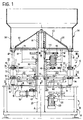
- a machine according to the invention comprises two associated structures, indicated 10 and 12, respectively.
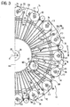
- the structure 10 is stationary and the other structure 12 is driven and rotates about a vertical axis A, as indicated by the arrow F1 in Figure 3.
- the stationary structure 10 comprises a framework 14 with a circular upper table 16.
- a cutting plane common to the blades 18 is indicated P in Figure 1.
- the axes of rotation B of the two circular blades 18 are vertical and parallel to the axis A of rotation of the rotary structure 12.
- the two circular blades 18 can be driven so as to rotate continuously as indicated by the arrows F2 ( Figures 2 and 3) by an electric motor 20, by means of a belt transmission 22 which rotates both of the blades 18, in a manner not shown.
- the table 16 supports a pair of support tracks 24 ( Figure 2) each of which extends between the two disc blades 18 along an arcuate path concentric with the axis of rotation A of the rotary structure 12.
- the table 16 of the stationary structure 10 also supports a circular cam 26 which is concentric with the axis A and the function of which will be explained further in the description with reference to Figure 5, and elsewhere.
- the framework 14 of the stationary structure 10 also comprises a central pillar 28 which supports the rotary structure 12 rotatably and which extends above the structure 12.
- the rotary structure 12 comprises a central sleeve 30 which surrounds an upper portion of the stationary pillar 28 on which it is mounted with the interposition of rolling-contact bearings 32.
- An array of rigid radial arms 34 extends from the sleeve 30, there being sixteen arms 34 in the embodiment shown.
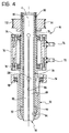
- Each of these arms 34 supports a respective supply unit 36, the details of which will be described below with reference to Figure 4.
- a geared electric motor unit 38 which rotates the entire rotary structure 12 by means of the sleeve 30 and by means of a pair of gears 40.
- the sleeve 30 supports the casing of a reduction unit 42 having gears with vertical axes.
- a toothed drive pulley 48 is keyed to the output shaft of the reduction unit 42.
- Each supply unit 46 has an upper, driven toothed pulley 50.
- the drive pulley 48 is connected to all of the driven pulleys 50 by means of a toothed transmission belt 52 which extends around the entire circumference of the rotary structure 12.
- the reduction unit 42 rotates about the pillar 28 and its input sprocket 46 circulates about the ring gear 44 in a manner of a satellite.
- the drive pulley 48 thus rotates the inner portions (described further below) of all of the supply units 36 simultaneously, with a suitable ratio.
- the rotary structure 12 also comprises a supply hopper 54 with a base wall 56 and a peripheral wall 58.
- the hopper 54 is fixed for rotation with the sleeve 30 by means of a radial array of right-angled support arms 60.
- the apron 62 is stationary, since it is keyed to an upper portion of the stationary pillar 28 by means of a central sleeve 66.
- a plurality of tubular appendages 68 extending from the periphery of the base wall 56 act as downward ducts, each aligned precisely with a supply duct, which will be referred to further below, of a respective supply unit 36.
- Cork stoppers (or other cylindrical cork elements) are loaded into the hopper 54, descend along the apron 62, and are mixed, so to speak, by the fins 64, finally falling into the downward ducts 68, descending in succession first through these ducts 68 and then through supply ducts which form part of the supply units 36, all of which will be explained further in the description with reference to Figures 6A and 6B.
- the unit 36 comprises a bush 70 which is fixed by means of lugs 72 to a respective radial arm 34 ( Figures 1 and 3) of the rotary structure 12.
- a tube 76 to an upper end of which the respective driven toothed pulley 50 is keyed, is mounted in the bush 70 by means of rolling-contact bearings 74 so as to be rotatable about an axis C.
- the axis C is parallel to the axes A and B and, in the embodiment shown, is also vertical.
- a supply duct 78 mounted coaxially in the tube 76 is aligned with a respective downward duct 68 coming from the hopper 54 ( Figure 1).
- the duct 78 is constituted by a tube of resilient material such as steel, the upper end of which is suspended in the tube 76.
- This suspension is achieved by means of a grub screw 80 engaged in a peripheral groove 82 of the duct 78.
- the duct 78 has a series of longitudinal slots 84 starting at a predetermined height and extending for a portion of the length of the duct 78 as far as a lower opening, indicated 86, of the duct or tube 78.
- the slots 84 divide the duct 78 into a circular series of petals 88 (for example, six petals) which act as jaws, as will be explained below.
- the petals 88 In the region of the opening 86, the petals 88 have respective outer enlarged portions 90 which together define a radially outer truncated cone converging towards the cutting plane P ( Figures 1, 6A and 6B) of the circular blades 18.
- the petals 88 are surrounded by a sleeve 92 mounted around the tube 76 so as to be slidable vertically.
- the sleeve 92 has a lower frustoconical inner surface 94 which corresponds to the truncated cone defined by the enlarged portions 90.
- a collar 96 is associated with the upper portion of the sleeve 92.
- a rolling-contact bearing 98 fixes the sleeve 92 and the collar 96 for translation together whilst allowing the sleeve 92 to rotate about its axis C, relative to the collar 96 and together with the tube 76 and with the duct or tube 78.
- pincer means 88 The function of the pincer means 88 will be explained further in the course of the description with reference to Figures 6A and 6B.
- This cam 26 has a face cam track which faces upwards and has raised portions 26a (Figure 2) in the region of the circular blades 18 and intermediate, recessed portions 26b, in order to perform the function which will be explained with reference to Figures 6A and 6B.
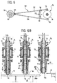
- Figure 5 shows a linkage, generally indicated 100, which serves to impart the above-mentioned movements to the collar 96 and hence to the sliding sleeve 92.
- the linkage 100 which is also visible in Figures 1 and 3, comprises a connecting rod with two arms 102. At one end, the two arms 102 are articulated, by means of a pin 104, to the central portion of the rotary structure constituted by the sleeve 30; at the other end, the two arms 102 of the connecting rod are articulated to the collar 96 by means of diametrally opposed pins 106 thereof.
- a cross-member 108 constituted by two spaced-apart portions, between which a cam follower 110 in the form of a small wheel is engaged, extends between the two arms 102 of the connecting rod.
- the wheel 110 is mounted rotatably on the two portions 108 of the cross-member by means of a pin 112 which extends radially relative to the machine.
- the cam-follower wheel 110 is in engagement with the circular cam 26 and follows its profile in order to bring about the upward and downward movements of the collar 96 and of the sleeve 92 during the rotation of the rotary element 12.
- the supply units 36 which follow one another from right to left may be the various units 36 of the circular series shown in Figure 3 but, for simplicity of explanation, it will be assumed that it is a single unit which moves continuously from right to left in the direction F1 during the execution of a cutting cycle.
- Positions of the unit are indicated S1, S2, S3, S4, S5 and S6, again from right to left, and are also shown in Figure 2.
- the cutting plane of the circular blades 18 is again indicated P.
- the support tracks are again indicated 24.
- the height of the support tracks 24 is adjustable in a manner not shown, so that the thickness of the discs to be cut from the stoppers, or from other cylindrical cork elements, which are stacked in succession in the duct 78, can be selected.
- each track 24 extends between an input region 24a and an output region 24b, which are also indicated in Figure 2.
- the input region 24a immediately follows a circular blade 18 and the output region 24b immediately precedes a circular blade.
- each support track 24 comprises an intermediate region 24c with an upward slope between the input region 24a and the output region 24b.
- the output region 24b is spaced from the cutting plane P of the blade by a distance H 1 equal to the thickness of the discs R to be cut; the input region 24a is spaced from the cutting plane P by a distance H 2 greater than the thickness H 1 and, in the case in question, greater the thickness or height of the remaining section W 0 .
- the pincer means are indicated conventionally by the reference numeral 88 which, in Figure 4, indicates the petals; the opening of the supply duct 78 is again indicated 86, as in Figure 4.
- the opening 86 is situated wholly in a region in which it is entirely facing the circular blade 18.
- the circular blade 18 cuts from the section W 0 a slice or disc R which falls into a suitable underlying container (not shown).
- the duct 78 then reaches position S5 ( Figure 6B) in which the pincer means 88 are released.
- the stack of stoppers W then descends by gravity and the remainder W R of the section W 0 comes to rest on the input region 24a of the next support track, being arranged entirely below the level of the pincer means 88.
- the remaining section W R is completely free and, since it is no longer dragged along, it remains substantially where it is on the track 24, from which it can be expelled by an arriving stopper W or section of stopper W 0 .
- the remaining section W R finally falls into another suitable container, other than that which collects the discs R, in order then to be retrieved, for example, in order to be transformed into granules for the production of reconstituted stoppers.
- the first, lowermost stopper W 1 of the series (position S6) can descend until it bears on the track 24 in order then to be sliced into discs R in accordance with the sequence described, starting from position S1.
- the duct 78 and its pincer means 88 of each group 36 are rotated in the same direction F2 as the circular blades 18 but so as to have a relative tangential shearing velocity substantially equal to the sum of the tangential velocities of the stoppers W and of the blades 18.
- the structure 10 which carries the circular blades 18 is stationary and the structure 12 which carries the supply units 36 rotates, but a machine according to the invention could be formed with the structure which carries the rotary blades being rotated and the structure which carries the supply units being kept stationary.
- the axes of rotation could also have an orientation other than vertical, for example, a horizontal orientation.
- the supply of the stoppers or other cylindrical elements in the respective ducts such as 76 would be achieved under a force other than that of gravity.
- FIG. 1 shows a machine which comprises two circular, driven blades 18 and a plurality of supply ducts 78 and respective pincer means 88, but a machine according to the invention could also comprise only one driven circular blade such as 18 and a single supply duct such as 78 with the respective pincer means such as 88, or more than two circular blades.
Landscapes
- Engineering & Computer Science (AREA)
- Mechanical Engineering (AREA)
- Life Sciences & Earth Sciences (AREA)
- Forests & Forestry (AREA)
- Chemical And Physical Treatments For Wood And The Like (AREA)
- Closures For Containers (AREA)
- Confectionery (AREA)
Applications Claiming Priority (2)
| Application Number | Priority Date | Filing Date | Title |
|---|---|---|---|
| IT1999TO000559 IT1308769B1 (it) | 1999-06-30 | 1999-06-30 | Macchina per la fabbricazione di rondelle di sughero, particolarmenteper turaccioli compositi. |
| ITTO990559 | 1999-06-30 |
Publications (2)
| Publication Number | Publication Date |
|---|---|
| EP1066935A2 true EP1066935A2 (de) | 2001-01-10 |
| EP1066935A3 EP1066935A3 (de) | 2003-03-05 |
Family
ID=11417923
Family Applications (1)
| Application Number | Title | Priority Date | Filing Date |
|---|---|---|---|
| EP00113533A Withdrawn EP1066935A3 (de) | 1999-06-30 | 2000-06-27 | Vorrichtung zur Herstellung von Korkscheiben, insbesonder für Zusammengesetzter Stopfen |
Country Status (2)
| Country | Link |
|---|---|
| EP (1) | EP1066935A3 (de) |
| IT (1) | IT1308769B1 (de) |
Cited By (2)
| Publication number | Priority date | Publication date | Assignee | Title |
|---|---|---|---|---|
| EP1772240A1 (de) * | 2005-10-10 | 2007-04-11 | David Navarro Salomo | Verfahren zur Herstellung von Korkscheiben und Maschine zur Herstellung von Korkscheiben nach diesem Verfahren |
| CN101428430B (zh) * | 2008-12-10 | 2011-04-20 | 王炎忠 | 寿司卷编织机 |
Family Cites Families (2)
| Publication number | Priority date | Publication date | Assignee | Title |
|---|---|---|---|---|
| US2328712A (en) * | 1940-12-31 | 1943-09-07 | W H Hutchinson & Son Inc | Cork-cutting machine |
| US3888151A (en) * | 1973-07-23 | 1975-06-10 | Frank S Beckerer | Cutting apparatus for strip stock |
-
1999
- 1999-06-30 IT IT1999TO000559 patent/IT1308769B1/it active
-
2000
- 2000-06-27 EP EP00113533A patent/EP1066935A3/de not_active Withdrawn
Cited By (2)
| Publication number | Priority date | Publication date | Assignee | Title |
|---|---|---|---|---|
| EP1772240A1 (de) * | 2005-10-10 | 2007-04-11 | David Navarro Salomo | Verfahren zur Herstellung von Korkscheiben und Maschine zur Herstellung von Korkscheiben nach diesem Verfahren |
| CN101428430B (zh) * | 2008-12-10 | 2011-04-20 | 王炎忠 | 寿司卷编织机 |
Also Published As
| Publication number | Publication date |
|---|---|
| ITTO990559A1 (it) | 2000-12-30 |
| EP1066935A3 (de) | 2003-03-05 |
| IT1308769B1 (it) | 2002-01-10 |
Similar Documents
| Publication | Publication Date | Title |
|---|---|---|
| CN110589045B (zh) | 一种摆动式食品包装装置 | |
| CN110561517B (zh) | 一种旋转式食品包装装置 | |
| CN111994853B (zh) | 一种用于鲍鱼罐头加工的自动封盖机 | |
| CN211417702U (zh) | 一种立式缠膜机 | |
| CN113059359B (zh) | 一种落杯及滤水盘上料装置 | |
| US20180077963A1 (en) | Automatic machine for strawberry de-calyx and cutting in pieces | |
| EP1066935A2 (de) | Vorrichtung zur Herstellung von Korkscheiben, insbesonder für Zusammengesetzter Stopfen | |
| CN1292637C (zh) | 苗木自动嫁接装置 | |
| CN115479796A (zh) | 一种食品安全检验采样装置 | |
| CN206870197U (zh) | 一种塑料瓶口自动切除机 | |
| US7219794B2 (en) | Adjustable guide chute and method for processing containers | |
| CN110509321A (zh) | 杏鲍菇批量修形自动化流水线 | |
| CN216005151U (zh) | 一种饮料灌装旋盖装置 | |
| JPH03216177A (ja) | 鱗茎の茎部と根部の切断装置 | |
| FI79965C (fi) | UTRUSTNING FOER ATT TILLSKAERA GAVELRONDELLER FOER EMBALLERING AV PAPPERSRULLAR. - SIIRRETTY PAEIVAEMAEAERAE-FOERSKJUTET DATUM PL 14 ç 13.09.85 - | |
| CN221110985U (zh) | 一种铝型材多向切割机 | |
| CN107160451B (zh) | 一种甘蔗切割设备 | |
| CN210633343U (zh) | 杯体割口机的自动上料机构 | |
| CN109730345B (zh) | 一种柑橘自动分瓣装置 | |
| EP2732892B1 (de) | Vorrichtung zum Abtrennen von Abschnitten von zylindrischen Werkstücken | |
| CN211996271U (zh) | 一种具有双工位吸头的气动翻转机构 | |
| CN117799025B (zh) | 一种立式竹筒开片机 | |
| CN209936726U (zh) | 一种双组份胶韩式花蝶成型机 | |
| CN221311304U (zh) | 自动涂覆生产线的甩篮定位装置 | |
| CN207901087U (zh) | 一种多工位旋转式工作机构 |
Legal Events
| Date | Code | Title | Description |
|---|---|---|---|
| PUAI | Public reference made under article 153(3) epc to a published international application that has entered the european phase |
Free format text: ORIGINAL CODE: 0009012 |
|
| AK | Designated contracting states |
Kind code of ref document: A2 Designated state(s): AT BE CH CY DE DK ES FI FR GB GR IE IT LI LU MC NL PT SE |
|
| AX | Request for extension of the european patent |
Free format text: AL;LT;LV;MK;RO;SI |
|
| PUAL | Search report despatched |
Free format text: ORIGINAL CODE: 0009013 |
|
| AK | Designated contracting states |
Kind code of ref document: A3 Designated state(s): AT BE CH CY DE DK ES FI FR GB GR IE IT LI LU MC NL PT SE Designated state(s): AT BE CH CY DE DK ES FI FR GB GR IE IT LI LU MC NL PT SE |
|
| AX | Request for extension of the european patent |
Extension state: AL LT LV MK RO SI |
|
| 17P | Request for examination filed |
Effective date: 20030808 |
|
| AKX | Designation fees paid |
Designated state(s): AT BE CH CY DE DK ES FI FR GB GR IE IT LI LU MC NL PT SE |
|
| 17Q | First examination report despatched |
Effective date: 20040819 |
|
| STAA | Information on the status of an ep patent application or granted ep patent |
Free format text: STATUS: THE APPLICATION IS DEEMED TO BE WITHDRAWN |
|
| 18D | Application deemed to be withdrawn |
Effective date: 20050301 |