EP1066744B1 - Wagen zum Transport eines Schneidwerks - Google Patents
Wagen zum Transport eines Schneidwerks Download PDFInfo
- Publication number
- EP1066744B1 EP1066744B1 EP00112984A EP00112984A EP1066744B1 EP 1066744 B1 EP1066744 B1 EP 1066744B1 EP 00112984 A EP00112984 A EP 00112984A EP 00112984 A EP00112984 A EP 00112984A EP 1066744 B1 EP1066744 B1 EP 1066744B1
- Authority
- EP
- European Patent Office
- Prior art keywords
- cutter
- supporting surface
- cutting unit
- waggon
- head
- Prior art date
- Legal status (The legal status is an assumption and is not a legal conclusion. Google has not performed a legal analysis and makes no representation as to the accuracy of the status listed.)
- Expired - Lifetime
Links
Images


Classifications
-
- A—HUMAN NECESSITIES
- A01—AGRICULTURE; FORESTRY; ANIMAL HUSBANDRY; HUNTING; TRAPPING; FISHING
- A01D—HARVESTING; MOWING
- A01D75/00—Accessories for harvesters or mowers
- A01D75/002—Carriers for the transport of harvesters or mowers
Definitions
- the invention relates to a carriage for transporting a cutting unit and a header cutter, especially for the rapeseed crop, with a first shelf on which the cutting unit can be placed, and a second shelf, on which the header cutter is separated can be removed from the cutting unit.
- rapeseed header cutters For rapeseed harvesting with a combine harvester, so-called rapeseed header cutters are used known that attachable to normal cutting units are and a cutting table extension with driven cutting blades, the cutting unit in the advancing direction of the combine harvester extended, as well as arranged on both sides of the cutting table Have side cutters.
- the cutting table extension and the Side cutters are appropriate to the rapeseed, which is a coherent Shrubbery makes to cut.
- the reapers are usually wider than the Highway Code is allowed to participate in road traffic They usually on a car hung on the combine harvester too transported to a field, where they then on the front of the Be attached to the combine harvester.
- rapeseed header cutters are used in the prior art, three ways to Transport known: First, the rapeseed header cutters on be transported in a separate car. Besides, they can, if they are attached to a cutting unit, together with the Cutting unit to be transported on a cart. Finally that can Cutting unit for harvesting by means of hydraulic cylinders extendible, and filler plates and the side cutters can be fixed to the extension. The side cutters and the Filling plates are transported separately.
- the essence of the invention is a carriage to provide, which has two shelves.
- the cutting unit can be stored while the Attachment cutter, which is especially needed for the rape harvest is separated from the cutting unit on a second shelf can be stored.
- the first shelf and the second shelf are mounted on the carriage movable relative to each other.
- the Invention thus allows the cutting unit and the Front cutting independently on the cart take off and transport.
- the cutting unit and the Attachment cutters are on the carriage relative to each other movably arranged so that the attachment cutter in the direction on the cutting unit to be moved and fixed to it.
- One on The second storage surface stored intent cutter can thus easily be brought in front of the cutting unit, which is stored on the first shelf, and finally attached to it.
- a separation of cutting unit and Front cutting unit is analogue, only in the opposite direction.
- the header cutter also during use on a field with the cutter too connect and disconnect as the dolly a sufficiently firm and flat storage surface for the Front cutting unit provides.
- the car is suitably equipped with a device for Attach to a vehicle provided.
- a device for Attach to a vehicle provided.
- towing vehicle can a Harvester, such as a combine harvester, but also a Tractor serve.
- the cutting unit and / or the attachment cutter floating or springing on the cart to store what through the suspension of the respective storage area on the car by means at least one spring can take place.
- the advantage is that any inaccuracies in positioning the feederhouse a combine harvester in front of the cutting unit through the suspension be balanced so that the coupling is facilitated. Also is the coupling of the header cutter to the cutting unit facilitated by the suspension.
- the first storage surface with respect to the Direction of travel of the car next to the second shelf be arranged, giving a relatively low center of gravity allows, but leads to a larger width of the car.
- the first shelf above or below be the second shelf, so that the width of the car is quite low, but the center of gravity is a bit higher.
- the relative movement between the first and second storage surface may be a pan and / or displacement movement.
- a drive can be provided, with which the Relative movement is achieved.
- the drive can be from a Towing vehicle, especially combine harvester supplied with energy become; in particular, he can electric motor, with a Hydraulic motor or cylinder or mechanically.
- One Electric motor can also be arranged by one on the car Battery to be powered by a Solar cell and / or one with a wheel of the car in Drive connection standing alternator is charged.
- a manual drive is conceivable that by a Operator takes place for example by means of a crank.
- the first and / or second Storage area in a relative to the direction of travel of the car to arrange laterally inclined plane.
- the angle of inclination is Preferably chosen such that it the coupling of the Cutting unit to a feeder of a combine harvester, or attached to a header conveyor on a feederhouse Cutting unit, allows.
- a harvesting machine shown in Figure 1 in the form of a Combine 10 is on front and rear driven steerable wheels 12 and 14 and has a driver's cab 16, from which they are operated by a driver can.
- a grain tank closes at the rear 18 on, the good delivered into it via an emptying tube 20 can give to the outside.
- the grain tank 18 is stored on a frame 22, in the supplied good on the way via a threshing drum 24, a concave 26 and a beater 28 in its large and small components are decomposed.
- FIG. 2 shows such a harvesting device in FIG Form of a cutting unit 48 reproduced on the front of the inclined conveyor 38 can be fixed.
- the cutting unit 48 has in a conventional manner, a reel 72 and a mower. Since the cutting unit 48 is relatively wide, it is in Figure 2 for Transport on a road on a cart 42 has been filed.
- the operator drives the combine harvester 10 to the in Figure 2 left side of the carriage 42 and pivots the feeder 38 in a conventional manner by means of a not shown in Figure 1 Hydraulic cylinder, so that a mechanical coupling between Inclined conveyor 38 and cutter 48 can be made.
- the cutting unit 48 is raised and the carriage 42nd be removed.
- the combine harvester 10 with the cutting unit 48 can then be used for harvesting.
- the deposition of the Header 48 on the carriage 42 happens in reverse Sequence.
- the car is equipped with a drawbar eye 50, with which he attached to the back of the combine 10 can be.
- the carriage 48 builds on a frame 52 with both sides arranged wheels 44, with respect to the (in the direction of travel considered) longitudinal dimension of the carriage 42 approximately centrally are arranged. It would also be feasible to have four or more wheels 44 to use.
- On the frame 52 is a first strut 59th attached, which extends approximately vertically upward, as well a second strut 54, which runs obliquely to the left above.
- the both struts 54, 59 support a first storage surface 60, on which the cutting unit 48 is stored.
- the first shelf 60 is slightly inclined laterally, so that the side of the Cutting unit 48, to which the feederhouse 38 is attached, at an edge 68 at the bottom - shown in Figure 2 left - Edge of the first shelf 60 is supported, located in the right Angle to the first shelf 60 extends to the top left.
- the edge 68 thus forms a support for the cutting unit 48.
- several struts 54, 59 in Direction of travel of the carriage 42 in a row with the frame 52nd be connected, which is also in the direction of travel of the Wagon 42 extends.
- the carriage 42 a second storage surface 56th provided, which arranged below the first shelf 56 is.
- the second storage surface 56 is on the first strut 59th hinged and a third strut 58 with a spring 57th connected, the other end is attached to the frame 52.
- the second shelf 56 resiliently on the car 42nd Attached, attaching one to the second shelf 56 stored intent cutter 46 on the cutting unit 48th facilitated.
- the second shelf 56 can be suspended resiliently, which in the figure 2 but not shown.
- the header cutter 46 consists in a conventional manner from a Cutting table extension with driven cutting blades and It is laterally attached side cutters 70th It is especially suitable for the harvest of rape.
- Target oilseed rape are harvested, the operator drives the combine harvester 10 with Inclined conveyor 38 attached cutting unit 48 (in Figure 2 of right) in front of the second shelf 56 in a position in which the cutter 48 and the header cutter 46 mechanically can be coupled to each other.
- the "threading" of the Cutting unit 48 in the header cutter 46 is characterized by the resilient suspension of the second shelf 56 crucial facilitated.
- the inclined conveyor 38 is slightly raised, and the header cutter 46 removed from the carriage 42.
- Harvest can the header cutter 46 in reverse order be stored again on the second shelf 56.
- Carriage 42 thus allows the attachment cutter 46 also on a field on which there is no solid, flat surface is to attach to the cutting unit 48 and to solve it. It would be also conceivable, the cutting unit 48 with it attached Insert cutting attachment 46 on the first storage surface 60, even if after a road transport the harvest of oilseed rape is intended.
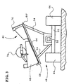
- FIG. 3 shows a carriage 42 according to a second embodiment represented the invention.
- a one-piece, relatively wide Storage surface 64, 64 ' serves both for storing the cutting unit 48 and the front cutter 46th
- the first shelf 64 is thus replaced by a first part of the one-piece Tray formed while its second part the second Deposit surface 64 'forms.
- the storage surface 64, 64 ' is as in Figure 2 slightly (relative to the direction of travel of the carriage 42) after tilted left and marked on the lower left with a right-angled upwardly extending edge 68 provided, on which the cutting unit 48 is supported.
- the Storage surface 64, 64 ' is about two struts 54 with the frame 52nd connected, wherein also several struts 54 in Forward direction of the carriage 42 arranged one behind the other could be; Also, two wheels 44, as in Figure 3 located, or four wheels 44 connected to the frame 52 be.
- the locking of the Front cutter 46 can be solved so that it through the Gravity on the second storage surface 64 'to the cutting unit 48th slides and can be attached to it.
- the cutting unit 48 can be attached to the inclined conveyor 38 of the combine 10 or be solved by it.
- To move the front cutter 46 can also be a separate drive, as in the third Embodiment of the invention, be provided, it also again separate from the cutter 48 against gravity can.
- the attachment cutter 46 may also be used of the inclined conveyor 38 in the drawn in Figure 3 Position are stored, which eliminates a separate drive.
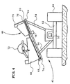
- FIG. 4 shows a carriage 42 according to a third embodiment of the invention reproduced in its basic Structure corresponds to the carriage 42 of the second embodiment. He has a (with respect to the direction of travel of the carriage 42) laterally slightly inclined to the left support surface 66, which about struts 54 is connected to the frame of the carriage 42, at the two Wheels 44 are arranged. At the bottom, left in Figure 4 Plotted edge of the support surface 66 extends a Edge 68 right-angled upwards; it serves to support the Cutting unit 48, which is stored on a first shelf 74 is located above the support surface 66 and itself from the edge 68 to about the middle of the support surface 66th extends.
- a second Tray 76 in the form of a movable, on wheels or Balls 80 stored slide provided on the support surface 66 .
- the second Storage area 76 serves to deposit the intent cutter 46th and in FIG. 4 is right next to the first storage surface 74 arranged.
- a drive 78 serves to the second shelf 76 with the laid on it cutting attachment 46 transverse to Moving forward direction of the carriage 42 so that the Front cutter 46 by means of the drive 78 in a position can be moved, in which it is coupled to the cutting unit can.
- the intent cutter 46 by means of Drive 78 are moved away again from the cutting unit 48.
- the Drive 78 operates hydraulically, electrically or mechanically, d. H. by a PTO device from the combine 10 driven, or is operated manually.
- the header cutter 46 may at the second shelf 76 (by a not drawn device) are locked; also can the second storage area 76 in its drawn in Figure 4 Position you during the transport of the car 42 takes, be locked on the carriage 42.
- the attachment of the cutting unit 48 on the inclined conveyor 38 of Combine 10 takes place in this embodiment, as well as the Laying the cutting unit 48 on the first shelf 74, such as described above with respect to the other embodiments of the side shown in Figure 4 left side.
- the Front cutting unit 46 if needed for harvesting operation is driven by the drive 78 in front of the cutting unit 48 and fastened thereto in a manner known per se. It can do that Cutting unit 48 on the inclined conveyor 38 of the combine 10th attached, or separated from it.
- the separation of Cutting unit 48 and cutting attachment 46 is analogous in reverse order, while also the cutting unit 48 am Inclined conveyor 38 may be attached or detached therefrom. Should the header cutter 46 is used again after transportation become unnecessary, a separation from the cutting 48.
Landscapes
- Life Sciences & Earth Sciences (AREA)
- Environmental Sciences (AREA)
- Harvesting Machines For Specific Crops (AREA)
- Combines (AREA)
Description
- Fig. 1
- eine Seitenansicht eines Mähdreschers;
- Fig. 2
- eine Frontansicht einer ersten Ausführungsform eines Wagens, die nicht unter den Umfang des Anspruchs 1 fällt,
- Fig. 3
- eine Frontansicht einer zweiten Ausführungsform eines Wagens, und
- Fig. 4
- eine Frontansicht einer dritten Ausführungsform eines Wagens.
Claims (11)
- Wagen (42) zum Transport eines Schneidwerks (48) und eines Vorsatzschneidwerks (46), insbesondere für die Rapsernte, mit einer ersten Ablagefläche (64, 74), auf der das Schneidwerk (48) ablegbar ist, und einer zweiten Ablagefläche (64', 76), auf der das Vorsatzschneidwerk (46) getrennt vom Schneidwerk (48) ablegbar ist, dadurch gekennzeichnet, daß die erste Ablagefläche (74) und die zweite Ablagefläche (76) relativ zueinander bewegbar sind, so daß ein auf der zweiten Ablagefläche (76) abgelegtes Vorsatzschneidwerk (46) in Richtung auf ein auf der ersten Ablagefläche (74) abgelegtes Schneidwerk (48) zu bewegbar und daran fixierbar ist.
- Wagen (42) nach Anspruch 1, gekennzeichnet durch eine Vorrichtung (50) zum Ankoppeln des Wagens (42) an ein Fahrzeug, insbesondere einen Mähdrescher (10).
- Wagen (42) nach Anspruch 1 oder 2, dadurch gekennzeichnet, daß das Schneidwerk (48) und/oder das Vorsatzschneidwerk (46) auf dem Wagen (42) federnd gelagert ist.
- Wagen (42) nach Anspruch 3, dadurch gekennzeichnet, daß die erste Ablagefläche (60) und/oder die zweite Ablagefläche (56) durch wenigstens eine Feder mit dem Wagen (42) verbunden ist.
- Wagen (42) nach einem der vorhergehenden Ansprüche, dadurch gekennzeichnet, daß die erste Ablagefläche (64, 74) bezüglich der Fahrtrichtung des Wagens (42) seitlich neben der zweiten Ablagefläche (64', 76) angeordnet ist.
- Wagen (42) nach einem der vorhergehenden Ansprüche, dadurch gekennzeichnet, daß die erste Ablagefläche (74) und die zweite Ablagefläche (76) relativ zueinander verschiebbar und/oder verschwenkbar sind.
- Wagen (42) nach einem der Ansprüche 1 bis 6, dadurch gekennzeichnet, daß die erste Ablagefläche (74) bzw. das Schneidwerk (48) und/oder die zweite Ablagefläche (76) bzw. das Vorsatzschneidwerk (46) durch einen Antrieb (78) bewegbar sind.
- Wagen (42) nach Anspruch 7, dadurch gekennzeichnet, daß der Antrieb (78) elektrisch und/oder hydraulisch und/oder mechanisch durch eine Erntemaschine angetrieben und/oder manuell arbeitet.
- Wagen (42) nach einem der vorhergehenden Ansprüche, dadurch gekennzeichnet, daß die erste Ablagefläche (64, 74) und/oder die zweite Ablagefläche (64, 76) am Wagen (42) arretierbar ist.
- Wagen (42) nach einem der vorhergehenden Ansprüche, dadurch gekennzeichnet, daß das Schneidwerk (48) an der ersten Ablagefläche (64, 74) und/oder das Vorsatzschneidwerk (46) an der zweiten Ablagefläche (64, 76) arretierbar ist.
- Wagen (42) nach einem der vorhergehenden Ansprüche, dadurch gekennzeichnet, daß die erste Ablagefläche (60, 64, 74) und/oder die zweite Ablagefläche (56, 64', 76) in seitlicher Richtung geneigt sind.
Priority Applications (1)
| Application Number | Priority Date | Filing Date | Title |
|---|---|---|---|
| DE20023484U DE20023484U1 (de) | 1999-07-07 | 2000-06-21 | Wagen zum Transport eines Schneidwerks |
Applications Claiming Priority (2)
| Application Number | Priority Date | Filing Date | Title |
|---|---|---|---|
| DE19931281A DE19931281A1 (de) | 1999-07-07 | 1999-07-07 | Wagen zum Transport eines Schneidwerks |
| DE19931281 | 1999-07-07 |
Publications (2)
| Publication Number | Publication Date |
|---|---|
| EP1066744A1 EP1066744A1 (de) | 2001-01-10 |
| EP1066744B1 true EP1066744B1 (de) | 2005-02-09 |
Family
ID=7913899
Family Applications (1)
| Application Number | Title | Priority Date | Filing Date |
|---|---|---|---|
| EP00112984A Expired - Lifetime EP1066744B1 (de) | 1999-07-07 | 2000-06-21 | Wagen zum Transport eines Schneidwerks |
Country Status (2)
| Country | Link |
|---|---|
| EP (1) | EP1066744B1 (de) |
| DE (2) | DE19931281A1 (de) |
Families Citing this family (6)
| Publication number | Priority date | Publication date | Assignee | Title |
|---|---|---|---|---|
| FR2813163B1 (fr) * | 2000-08-25 | 2003-02-21 | Perard | Chariot de transport de barre de coupe de moissonneuse batteuse ou similaire |
| DE10064961A1 (de) * | 2000-12-23 | 2002-06-27 | Deere & Co | Transportwagen |
| DE10240513A1 (de) * | 2002-09-03 | 2004-03-11 | Claas Selbstfahrende Erntemaschinen Gmbh | Schneidwerkswagen |
| DE102012102084B4 (de) | 2012-03-13 | 2014-05-15 | Cnh Belgium Nv | Verlade- und Transportvorrichtung für landwirtschaftliche Schneidwerke |
| CN105830649A (zh) * | 2016-05-16 | 2016-08-10 | 常州格力博有限公司 | 悬架装置及其割草机 |
| US10729057B2 (en) | 2018-11-30 | 2020-08-04 | Cnh Industrial America Llc | Integrated upright header transport for an agricultural combine |
Family Cites Families (9)
| Publication number | Priority date | Publication date | Assignee | Title |
|---|---|---|---|---|
| NL6402854A (de) * | 1964-03-18 | 1965-09-20 | ||
| US3413014A (en) * | 1966-09-26 | 1968-11-26 | Newton Mfg Co | Transportation means for combine header or the like |
| US3608753A (en) * | 1969-05-23 | 1971-09-28 | Ronald J Scott | Combine header and transport apparatus |
| DE2311721A1 (de) * | 1973-03-09 | 1974-09-12 | Claas Maschf Gmbh Geb | Transportwagen fuer frontanbaugruppen von maehmaschinen, insbesondere maehdreschern |
| US4371299A (en) * | 1980-07-24 | 1983-02-01 | Deere & Company | Trailer frame |
| US4770577A (en) * | 1985-05-03 | 1988-09-13 | Farris Gary C | Transport vehicle for combine harvester headers |
| US4834598A (en) * | 1987-06-22 | 1989-05-30 | Bruns Wesley W | Combine head carrier for transport vehicle |
| IT1223703B (it) * | 1988-07-18 | 1990-09-29 | Fiatgeotech | Carrello per il trasporto di organi di macchine agricole particolarmente piattaforme di taglio di macchine mietitrebbiatrici |
| US5529447A (en) * | 1994-11-28 | 1996-06-25 | May-Wes Manufacturing, Inc. | Combined header transport vehicle |
-
1999
- 1999-07-07 DE DE19931281A patent/DE19931281A1/de not_active Withdrawn
-
2000
- 2000-06-21 DE DE50009452T patent/DE50009452D1/de not_active Expired - Lifetime
- 2000-06-21 EP EP00112984A patent/EP1066744B1/de not_active Expired - Lifetime
Also Published As
| Publication number | Publication date |
|---|---|
| DE19931281A1 (de) | 2001-01-11 |
| DE50009452D1 (de) | 2005-03-17 |
| EP1066744A1 (de) | 2001-01-10 |
Similar Documents
| Publication | Publication Date | Title |
|---|---|---|
| EP1046329B2 (de) | Fahrzeug für den Einsatz in der Landwirtschaft, insbesondere einen Feldhäcksler oder Mähdrescher, mit einem daran angebauten Zusatzgerät | |
| DE3006871C2 (de) | Selbstfahrender Mähdrescher | |
| EP0045039B1 (de) | Ladefahrzeug zur Aufnahme einer Erntebergungsvorrichtung | |
| DE602004009338T2 (de) | Landmaschine zum schwaden von auf dem boden liegenden produkten | |
| EP3090617B1 (de) | Fahrbare erntemaschine und verfahren zum ernten von pflanzenteilen | |
| EP0212185B1 (de) | Mähdrescher | |
| DE1482245A1 (de) | Rueben-Erntegeraet fuer Selbstladewagen | |
| EP1066744A1 (de) | Wagen zum Transport eines Schneidwerks | |
| DE1582455A1 (de) | Ladewagen | |
| DE102004059038B4 (de) | Kombination aus einer Erntemaschine, einem Erntevorsatz und einem Wagen zur Abstützung des Erntevorsatzes | |
| DE2712991A1 (de) | Landmaschine mit umbaubarer aufnehmereinrichtung | |
| AT393770B (de) | Aufsammeleinrichtung einer mit einem selbstfahrenden fahrzeug kuppelbaren landwirtschaftlichen erntemaschine | |
| WO2012152249A1 (de) | Vorrichtung und verfahren zum transport von tieren | |
| DE2533757C2 (de) | Mähdrescher | |
| EP1588601B1 (de) | Erntemaschine mit einer Austrageinrichtung | |
| DE2046552A1 (de) | Schlepper mit verschiebbarem Fahrer sitz | |
| DE202011101157U1 (de) | Landwirtschaftliche Maschine | |
| DE102022105847A1 (de) | Schwadaufnehmer mit drittem Stützrad | |
| DE3801895A1 (de) | Vorrichtung an der frontseite eines ackerschleppers zum anheben eines zusatzgewichttraegers in eine transportstellung | |
| EP1219152B1 (de) | Transportwagen eines Schneidewerks | |
| DE20023484U1 (de) | Wagen zum Transport eines Schneidwerks | |
| EP0056873A1 (de) | Vorrichtung zum Aufnehmen von Rüben | |
| DE2554746A1 (de) | Vorrichtung zur bearbeitung grossflaechiger abschnitte von nutzungsflaechen | |
| BE1031908B1 (de) | Erntevorsatz für eine selbstfahrende Erntemaschine | |
| DE1755729A1 (de) | Landwirtschaftlicher wagen |
Legal Events
| Date | Code | Title | Description |
|---|---|---|---|
| PUAI | Public reference made under article 153(3) epc to a published international application that has entered the european phase |
Free format text: ORIGINAL CODE: 0009012 |
|
| AK | Designated contracting states |
Kind code of ref document: A1 Designated state(s): BE DE DK FI FR IT |
|
| AX | Request for extension of the european patent |
Free format text: AL;LT;LV;MK;RO;SI |
|
| 17P | Request for examination filed |
Effective date: 20010710 |
|
| AKX | Designation fees paid |
Free format text: BE DE DK FI FR IT |
|
| 17Q | First examination report despatched |
Effective date: 20030822 |
|
| GRAP | Despatch of communication of intention to grant a patent |
Free format text: ORIGINAL CODE: EPIDOSNIGR1 |
|
| GRAS | Grant fee paid |
Free format text: ORIGINAL CODE: EPIDOSNIGR3 |
|
| GRAA | (expected) grant |
Free format text: ORIGINAL CODE: 0009210 |
|
| AK | Designated contracting states |
Kind code of ref document: B1 Designated state(s): BE DE DK FI FR IT |
|
| PG25 | Lapsed in a contracting state [announced via postgrant information from national office to epo] |
Ref country code: IT Free format text: LAPSE BECAUSE OF FAILURE TO SUBMIT A TRANSLATION OF THE DESCRIPTION OR TO PAY THE FEE WITHIN THE PRESCRIBED TIME-LIMIT;WARNING: LAPSES OF ITALIAN PATENTS WITH EFFECTIVE DATE BEFORE 2007 MAY HAVE OCCURRED AT ANY TIME BEFORE 2007. THE CORRECT EFFECTIVE DATE MAY BE DIFFERENT FROM THE ONE RECORDED. Effective date: 20050209 Ref country code: FI Free format text: LAPSE BECAUSE OF FAILURE TO SUBMIT A TRANSLATION OF THE DESCRIPTION OR TO PAY THE FEE WITHIN THE PRESCRIBED TIME-LIMIT Effective date: 20050209 |
|
| REF | Corresponds to: |
Ref document number: 50009452 Country of ref document: DE Date of ref document: 20050317 Kind code of ref document: P |
|
| PG25 | Lapsed in a contracting state [announced via postgrant information from national office to epo] |
Ref country code: DK Free format text: LAPSE BECAUSE OF FAILURE TO SUBMIT A TRANSLATION OF THE DESCRIPTION OR TO PAY THE FEE WITHIN THE PRESCRIBED TIME-LIMIT Effective date: 20050509 |
|
| PG25 | Lapsed in a contracting state [announced via postgrant information from national office to epo] |
Ref country code: BE Free format text: LAPSE BECAUSE OF NON-PAYMENT OF DUE FEES Effective date: 20050630 |
|
| PLBE | No opposition filed within time limit |
Free format text: ORIGINAL CODE: 0009261 |
|
| STAA | Information on the status of an ep patent application or granted ep patent |
Free format text: STATUS: NO OPPOSITION FILED WITHIN TIME LIMIT |
|
| ET | Fr: translation filed | ||
| 26N | No opposition filed |
Effective date: 20051110 |
|
| BERE | Be: lapsed |
Owner name: DEERE & CY Effective date: 20050630 |
|
| PGFP | Annual fee paid to national office [announced via postgrant information from national office to epo] |
Ref country code: FR Payment date: 20140617 Year of fee payment: 15 |
|
| REG | Reference to a national code |
Ref country code: DE Ref legal event code: R081 Ref document number: 50009452 Country of ref document: DE Owner name: ZUERN HARVESTING GMBH & CO. KG, DE Free format text: FORMER OWNER: DEERE & COMPANY, MOLINE, ILL., US Effective date: 20150331 |
|
| REG | Reference to a national code |
Ref country code: FR Ref legal event code: ST Effective date: 20160229 |
|
| PG25 | Lapsed in a contracting state [announced via postgrant information from national office to epo] |
Ref country code: FR Free format text: LAPSE BECAUSE OF NON-PAYMENT OF DUE FEES Effective date: 20150630 |
|
| PGFP | Annual fee paid to national office [announced via postgrant information from national office to epo] |
Ref country code: DE Payment date: 20160830 Year of fee payment: 17 |
|
| REG | Reference to a national code |
Ref country code: DE Ref legal event code: R119 Ref document number: 50009452 Country of ref document: DE |
|
| PG25 | Lapsed in a contracting state [announced via postgrant information from national office to epo] |
Ref country code: DE Free format text: LAPSE BECAUSE OF NON-PAYMENT OF DUE FEES Effective date: 20180103 |