EP1065365B1 - Abgasrückführventil - Google Patents
Abgasrückführventil Download PDFInfo
- Publication number
- EP1065365B1 EP1065365B1 EP00109770A EP00109770A EP1065365B1 EP 1065365 B1 EP1065365 B1 EP 1065365B1 EP 00109770 A EP00109770 A EP 00109770A EP 00109770 A EP00109770 A EP 00109770A EP 1065365 B1 EP1065365 B1 EP 1065365B1
- Authority
- EP
- European Patent Office
- Prior art keywords
- exhaust gas
- gas recirculation
- cylinder head
- line
- valve
- Prior art date
- Legal status (The legal status is an assumption and is not a legal conclusion. Google has not performed a legal analysis and makes no representation as to the accuracy of the status listed.)
- Expired - Lifetime
Links
- 239000000498 cooling water Substances 0.000 claims description 10
- 238000002485 combustion reaction Methods 0.000 claims description 8
- 238000001816 cooling Methods 0.000 claims description 4
- 238000002156 mixing Methods 0.000 claims description 3
- 230000001105 regulatory effect Effects 0.000 claims description 2
- 238000011144 upstream manufacturing Methods 0.000 claims 3
- 239000007789 gas Substances 0.000 description 160
- 239000000203 mixture Substances 0.000 description 6
- 230000015572 biosynthetic process Effects 0.000 description 4
- 239000003973 paint Substances 0.000 description 4
- 239000004071 soot Substances 0.000 description 4
- 239000000853 adhesive Substances 0.000 description 2
- 230000001070 adhesive effect Effects 0.000 description 2
- 239000003054 catalyst Substances 0.000 description 2
- 239000004922 lacquer Substances 0.000 description 2
- 239000000463 material Substances 0.000 description 2
- 238000013021 overheating Methods 0.000 description 2
- 238000000926 separation method Methods 0.000 description 2
- 238000009423 ventilation Methods 0.000 description 2
- 239000002826 coolant Substances 0.000 description 1
- 238000013461 design Methods 0.000 description 1
- 238000011161 development Methods 0.000 description 1
- 239000012530 fluid Substances 0.000 description 1
- 238000002386 leaching Methods 0.000 description 1
- 238000000034 method Methods 0.000 description 1
- 238000012549 training Methods 0.000 description 1
Images


Classifications
-
- F—MECHANICAL ENGINEERING; LIGHTING; HEATING; WEAPONS; BLASTING
- F02—COMBUSTION ENGINES; HOT-GAS OR COMBUSTION-PRODUCT ENGINE PLANTS
- F02M—SUPPLYING COMBUSTION ENGINES IN GENERAL WITH COMBUSTIBLE MIXTURES OR CONSTITUENTS THEREOF
- F02M26/00—Engine-pertinent apparatus for adding exhaust gases to combustion-air, main fuel or fuel-air mixture, e.g. by exhaust gas recirculation [EGR] systems
- F02M26/65—Constructional details of EGR valves
- F02M26/72—Housings
- F02M26/73—Housings with means for heating or cooling the EGR valve
-
- F—MECHANICAL ENGINEERING; LIGHTING; HEATING; WEAPONS; BLASTING
- F02—COMBUSTION ENGINES; HOT-GAS OR COMBUSTION-PRODUCT ENGINE PLANTS
- F02M—SUPPLYING COMBUSTION ENGINES IN GENERAL WITH COMBUSTIBLE MIXTURES OR CONSTITUENTS THEREOF
- F02M26/00—Engine-pertinent apparatus for adding exhaust gases to combustion-air, main fuel or fuel-air mixture, e.g. by exhaust gas recirculation [EGR] systems
- F02M26/13—Arrangement or layout of EGR passages, e.g. in relation to specific engine parts or for incorporation of accessories
- F02M26/17—Arrangement or layout of EGR passages, e.g. in relation to specific engine parts or for incorporation of accessories in relation to the intake system
- F02M26/21—Arrangement or layout of EGR passages, e.g. in relation to specific engine parts or for incorporation of accessories in relation to the intake system with EGR valves located at or near the connection to the intake system
-
- F—MECHANICAL ENGINEERING; LIGHTING; HEATING; WEAPONS; BLASTING
- F02—COMBUSTION ENGINES; HOT-GAS OR COMBUSTION-PRODUCT ENGINE PLANTS
- F02M—SUPPLYING COMBUSTION ENGINES IN GENERAL WITH COMBUSTIBLE MIXTURES OR CONSTITUENTS THEREOF
- F02M26/00—Engine-pertinent apparatus for adding exhaust gases to combustion-air, main fuel or fuel-air mixture, e.g. by exhaust gas recirculation [EGR] systems
- F02M26/13—Arrangement or layout of EGR passages, e.g. in relation to specific engine parts or for incorporation of accessories
- F02M26/22—Arrangement or layout of EGR passages, e.g. in relation to specific engine parts or for incorporation of accessories with coolers in the recirculation passage
- F02M26/29—Constructional details of the coolers, e.g. pipes, plates, ribs, insulation or materials
- F02M26/32—Liquid-cooled heat exchangers
-
- F—MECHANICAL ENGINEERING; LIGHTING; HEATING; WEAPONS; BLASTING
- F02—COMBUSTION ENGINES; HOT-GAS OR COMBUSTION-PRODUCT ENGINE PLANTS
- F02M—SUPPLYING COMBUSTION ENGINES IN GENERAL WITH COMBUSTIBLE MIXTURES OR CONSTITUENTS THEREOF
- F02M26/00—Engine-pertinent apparatus for adding exhaust gases to combustion-air, main fuel or fuel-air mixture, e.g. by exhaust gas recirculation [EGR] systems
- F02M26/52—Systems for actuating EGR valves
- F02M26/53—Systems for actuating EGR valves using electric actuators, e.g. solenoids
- F02M26/54—Rotary actuators, e.g. step motors
-
- F—MECHANICAL ENGINEERING; LIGHTING; HEATING; WEAPONS; BLASTING
- F02—COMBUSTION ENGINES; HOT-GAS OR COMBUSTION-PRODUCT ENGINE PLANTS
- F02M—SUPPLYING COMBUSTION ENGINES IN GENERAL WITH COMBUSTIBLE MIXTURES OR CONSTITUENTS THEREOF
- F02M26/00—Engine-pertinent apparatus for adding exhaust gases to combustion-air, main fuel or fuel-air mixture, e.g. by exhaust gas recirculation [EGR] systems
- F02M26/65—Constructional details of EGR valves
- F02M26/66—Lift valves, e.g. poppet valves
- F02M26/67—Pintles; Spindles; Springs; Bearings; Sealings; Connections to actuators
Definitions
- the invention relates to an exhaust gas recirculation system for an internal combustion engine with a cylinder head associated Inlet and outlet piping of a cylinder head, the has a charge air line, which via an exhaust gas recirculation line and an exhaust gas recirculation valve is supplied to exhaust gas, wherein the exhaust gas recirculation valve, seen in the flow direction, after the cylinder head and in front of a separate exhaust gas supply is arranged, which is formed as a mixing device is.
- JP-A-11082184 also shows an exhaust gas recirculation system, at the inside of an exhaust gas recirculation line a control valve is arranged.
- the control valve is here provided in front of a charge air distributor.
- the document D 3 (DE 197 25 668 C1) shows an exhaust gas recirculation device with two inlet openings for fresh air and Exhaust gas and two outlet openings for fresh air and exhaust gas, wherein the exhaust gas outlet opening is centered in the outlet opening is arranged for fresh air.
- the invention task is the exhaust gas recirculation valve and form the exhaust gas supply device in such a way and arrange that a maintenance-free exhaust gas recirculation and an optimal exhaust gas temperature is ensured.
- the object is achieved according to the invention characterized in that the exhaust gas recirculation valve directly behind the cylinder head in the area the cold side of the cylinder head of the internal combustion engine arranged is and to a built-in cylinder head part the exhaust gas recirculation line connects.
- This is achieved that the temperature level of the exhaust gases in the integrated part of Exhaust pipe is sufficiently reduced and thus the materials Do not overstress the exhaust gas recirculation valve become.
- the temperature level of the exhaust gases is still sufficiently high to cause the valve or valve seat to become lightly baked to avoid.
- the actuating forces of the valve are effectively reduced to the adhesive forces of the paint layer in the valve seat.
- the exhaust gas recirculation valve This can be anywhere between the cylinder head and Abgaszu211 leverage be provided. By the separation of the exhaust gas recirculation valve from that in the fresh air entrained ⁇ 1 the crankcase breather is also clogging by a soot-oil mixture prevented.
- the integrated part of the exhaust gas recirculation line inside the cylinder head from the exhaust side running to the inlet side, between an end face of the Cylinder head and an outer cylinder is provided.
- the temperature level the exhaust gas is after the internal part of the return line still high enough to light the valve or the valve seat to avoid.
- the temperature level the exhaust gases in the integrated part of the exhaust pipe sufficiently reduced and thus the materials of the exhaust gas recirculation valve not overused.
- the external part of the exhaust gas recirculation line has two channels, wherein the first channel is connected to the cooling water circuit of the cylinder head and the second channel serves as the actual exhaust gas recirculation line and that between the cylinder head and the external part of the exhaust gas recirculation line another valve for regulation the cooling water flow is provided in this part of the exhaust gas recirculation line.
- the first channel or the cooling water channel is in this case via the exhaust gas recirculation valve with the cooling water circuit of the cylinder head in operative connection.
- the exhaust gas recirculation valve With the distance of the exhaust gas recirculation valve to the cylinder head thus the associated exhaust gas temperature can be varied.
- the exhaust gas recirculation valve is in operative connection with a cooling device of the cylinder head.
- the exhaust gas recirculation valve ge cools and thus the actuator of the exhaust gas recirculation valve are protected against overheating in case of need or at full load.
- the exhaust gas supply an inlet for fresh air and an inlet opening for exhaust gas and an outlet for Fresh air and an outlet for exhaust gas, wherein the outlet for exhaust gas centric in the outlet opening is arranged for fresh air.
- the temperature level of the exhaust gases sink the critical area. The lacquer formation would thus favors, with the leaching of the flow channels at this Make no impact on the functioning of the exhaust gas supply Has.
- the exhaust gas supply occurs although with the fresh air flow and thus also with the Fresh air flow entrained crankcase breather oil Contact, due to the centric inflow of the exhaust gas in but the fresh air flow is the over the fresh air flow entrained 6l of the crankcase ventilation and the soot content evenly mixed in the wake of the outlet opening or distributed and thus carried by the fresh air flow. Also the oil carried along the wall of the fresh air duct leads into Connection with the centric inflowing soot not to a clogging of the cable cross-sections. The lacquer formation and the clogging of the exhaust gas supply device or the guide channels is thus prevented.
- the exhaust gas recirculation valve a pneumatic or electro-mechanically operated actuator with one in the closed position of the exhaust gas recirculation valve having self-locking actuator.
- the electro mechanical actuator sits directly on the exhaust gas recirculation valve and is controlled via the motor cable set.
- the pneumatic control and the electro-pneumatic converter fall in this Training away.
- the inlet opening for Fresh air to the charge air line, the inlet opening for Exhaust gas to the external exhaust gas recirculation line, the outlet opening for fresh air to the charge air distributor and the outlet openings for exhaust also to the charge air manifold are connected.
- the exhaust gas flow is thus the fresh air flow admixed. After the centric outlet of the exhaust gas in the fresh air flow begins the mixing process of the two Gas streams. This produces no significant soot- ⁇ 1 deposits in the field of exhaust gas supply and clogging will be prevented.
- the exhaust gas recirculation valve in Seen flow direction directly in front of the Abgaszu211 landmark is provided, wherein the exhaust gas recirculation valve and the exhaust gas supply functionally arranged in a housing and via the inlet opening for exhaust gas in flow connection are.
- the functional separation of exhaust gas recirculation valve and exhaust gas supply device ensures that the exhaust gas recirculation valve does not flow around the fresh air flow and thus not is cooled.
- Fig. 1 with 5 an on and with 2 denotes an exhaust pipe system of an internal combustion engine, not shown, which is equipped with an exhaust gas recirculation system 1 1.
- an air filter 13 On the outlet side, an air filter 13 is provided, to which a fresh air charger 15 and a charge air line 8 is connected.
- a catalyst 14 On the outlet side is a catalyst 14, to which an exhaust system 16 is connected.
- a charge air cooler 6 In the charge air line 8, a charge air cooler 6 is integrated and after the charge air line 8 is a Abgaszulite shimmer 10.
- the Abgaszulite shimmer 10 is connected via an external part 4 'of the exhaust gas recirculation line with an exhaust gas recirculation valve 9, via an integrated part 4 of the exhaust gas recirculation line to the outlet side of Internal combustion engine communicates.
- the exhaust gas supply device 10 is connected via a charge air distributor 7 to intake ports 17.
- the fresh air is sucked in via the air filter 13 and compressed by the fresh air charger 15.
- the fresh air charger 15 is driven on the exhaust side of the outflowing exhaust gases, which then flow through the catalyst 14 and the exhaust system 16 to the outside.
- the compressed fresh air is called charge air in the intercooler 6 cooled and continue on the charge air line 8 and the Abgaszucited modelling 10 supplied to the charge air manifold 7.
- the compressed and cooled Fresh air exhaust gas added.
- the exhaust gas is here via the integrated in a cylinder head 3 Part 4 of the exhaust gas recirculation line the exhaust gas recirculation valve 9 is supplied. over the external part 4 'of the exhaust gas recirculation line is so regulated Exhaust gas passed to the exhaust gas supply device 10.
- the exhaust gas recirculation valve 9 regulates via a controller 11 (FIG. the supplied in the exhaust gas supply 10 of the fresh air Exhaust gas flow, so that in the charge air manifold 7 a homogeneous Fresh air exhaust gas mixture is formed.
- This homogeneous fresh air exhaust gas mixture is shown via the inlet channels 17 in Fig. 2 Cylinders 18 supplied.
- the integrated part 4 of the exhaust gas recirculation line runs within of the cylinder head 3 from the exhaust side to the intake side and connects to the exhaust gas recirculation valve 9.
- the external part 4 'of the exhaust gas recirculation line has two channels 27, 28, wherein the first channel 28 with the cooling water circuit the cylinder head is connected and the second channel 27 serves as the actual exhaust gas recirculation line.
- Between the cylinder head 3 and the external part 4 'of the exhaust gas recirculation line is another, not shown valve for regulation the cooling water flow in this part of the exhaust gas recirculation line provided, depending on the operating point the exhaust gas temperature can be controlled.
- Fig. 2 the inventive arrangement of the exhaust gas recirculation valve 9 and the exhaust gas supply device 10 in connection with the inlet and outlet piping system 5, 2 is shown schematically. It is advantageous that the exhaust gas recirculation valve 9 and the exhaust gas supply device 10 are arranged separately. In this context, it is also possible to provide the exhaust gas recirculation valve 9 seen in the flow direction at the end of the external part 4 'of the exhaust gas recirculation line and to arrange it with the exhaust gas supply device 10 of the type in a common housing, that the exhaust gas recirculation valve 9 is still arranged in the exhaust stream on the one hand and on the other is not cooled by the fresh air stream.
- the exhaust gas recirculation valve 9 is directly behind the cylinder head. 3 arranged in the region of the cold side of the internal combustion engine and is via the integrated part 4 of the exhaust gas recirculation line, between an end face of the cylinder head 3 and the outer cylinder 18 is provided with exhaust gas.
- the exhaust gas supply device 10 is, seen in the flow direction, arranged in front of the charge air distributor 7 and is connected via the external part 4 'of the exhaust gas recirculation line from the exhaust gas recirculation valve 9 supplied with exhaust gas. About the charge air manifold 7 and the intake ports 17 will be the fresh air exhaust mixture to the cylinders 18 supplied.
- the external part 4 'of the exhaust gas recirculation line and the exhaust gas recirculation valve 9 stand with the cooling water circuit of the cylinder head 3 in operative connection.
- the operating temperature of the exhaust gas in Exhaust gas recirculation valve 9 and in the external part 4 'of the exhaust gas recirculation line be controlled via the cooling water flow.
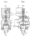
- FIGS. 3 and 4 each show a section of the exhaust gas recirculation valve 9 with the integrated Abgaszu slaughter 10.
- the Exhaust gas recirculation valve 9 has a valve body 23, a control axis 24, an actuator 25 and a servomotor 26, which are arranged coaxially with respect to a valve axis 29.
- the adjusting axis 24 and thus the valve body 23 are over the intended actuator 25, which is designed as a cam, by means of a rotational movement of the servomotor 26 vertically between their two end positions moved.
- the valve body 23 in both end positions self-locking, i. in the closed state holds the upcoming exhaust gas pressure Valve closed and in open condition is the servomotor due to the cam arrangement force or torque free.
- the fresh air flow occurs left through an inlet opening 19 for fresh air into the exhaust gas supply 10 and becomes radial, here from below, Charged with exhaust gas via an inlet opening 20 for exhaust gas.
- the exhaust gas flow passes through an exhaust gas outlet opening 22 in the fluid axis 30 of the fresh air flow on and is on the way to the charge air distributor 7 or in the charge air distributor 7 mixed.
- the fresh air flow causes oil to escape from the crankcase breather carried. This entrained oil and the soot content of the mixed exhaust gas are partially mixed and thus by carried the gas stream.
- the fresh air-exhaust mixture is supplied via the inlet ports 17 to the cylinders 18.
- Fig. 5 is shown with 31 en housing that the exhaust gas recirculation valve 9 and the Abgaszu 1500voriques 10 receives.
- the housing 31 has a separating surface 32, which is the exhaust gas recirculation valve 9 separates from the fresh air flow, so this is not cooled by the fresh air stream.
- the exhaust gases occur in this case from the exhaust gas recirculation valve 9 via the inlet opening 20 for exhaust gas in the Abgaszu 1500voriques 10th and are with the entering through the inlet opening 19 Fresh air mixed.
- About the outlet opening 21 and 22nd the gas mixture is fed to the charge air manifold.
Landscapes
- Engineering & Computer Science (AREA)
- Chemical & Material Sciences (AREA)
- Combustion & Propulsion (AREA)
- Mechanical Engineering (AREA)
- General Engineering & Computer Science (AREA)
- Exhaust-Gas Circulating Devices (AREA)
Description
Von besonderer Bedeutung ist für die vorliegende Erfindung, daß das Abgasrückführventil mit einer Kühleinrichtung des Zylinderkopfs in Wirkverbindung steht. Hierdurch kann im Bedarfsfall bzw. im Vollastbetrieb das Abgasrückführventil ge kühlt und damit der Steller des Abgasrückführventils vor Überhitzung geschützt werden.
- Figur 1
- eine perspektivische Darstellung des Ein- und Auslaßleitungssystems einer Brennkraftmaschine,
- Figur 2
- eine schematische Darstellung der erfindungsgemäßen Abgasrückführeinrichtung in der Ansicht von oben gemäß Fig. 1,
- Figur 3
- Eine Schnittdarstellung eines Abgasrückführventils mit integrierter Abgaszuführeinrichtung entlang der Linie B-B in Fig. 4,
- Figur 4
- Eine Schnittdarstellung eines Abgasrückführventils mit integrierter Abgaszuführeinrichtung entlang der Linie A-A in Fig. 3,
- Figur 5
- eine schematische Darstellung des Abgasrückführventils und der Abgaszuführeinrichtung in einem Gehäuse.
Die Frischluft wird über den Luftfilter 13 angesaugt und mittels des Frischluftladers 15 verdichtet. Der Frischluftlader 15 wird abgasseitig von den ausströmenden Abgasen angetrieben, die dann über den Katalysator 14 und die Abgasanlage 16 ins Freie ausströmen.
Claims (10)
- Abgasrückführanlage (1) für eine Brennkraftmaschine mit einem an einen Zylinderkopf (3) anschließbares Ein- und Auslaßleitungssystem (5, 2), das eine Ladeluftleitung (8) aufweist, der über eine Abgasrückführleitung und ein Abgasrückführventil (9) Abgas zugeführt wird, wobei das Abgasrückführventil (9), in Strömungsrichtung gesehen, nach dem Zylinderkopf (3) anbringbar und vor einer davon getrennten Abgaszuführeinrichtung (10) angeordnet ist, die als Mischvorrichtung ausgebildet ist,
dadurch gekennzeichnet, daß das Abgasrückführventil (9) direkt hinter dem Zylinderkopf (3) im Bereich der kalten Seite des Zylinderkopfs (3) der Brennkraftmaschine angeordnet ist und an einen im Zylinderkopf (3) integrierten Teil (4) der Abgasrückführleitung anschließt. - Abgasrückführanlage nach Anspruch 1,
dadurch gekennzeichnet, daß der integrierte Teil (4) der Abgasrückführleitung innerhalb des Zylinderkopfs (3) von der Auslaßseite zur Einlaßseite verlaufend, zwischen einer Stirnseite des Zylinderkopfs (3) und einem äußeren Zylinder (18) vorgesehen ist. - Abgasrückführanlage nach Anspruch 2,
dadurch gekennzeichnet, daß die Abgasrückführleitung aus dem im Zylinderkopf (3) integrierten Teil (4) und einem externen Teil (4') besteht, wobei dem im oder anschließend an den externen Teil (4') der Abgasrückführleitung angeordneten Abgasrückführventil (9) eine davon getrennte Abgaszuführeinrichtung (10) zugeordnet ist, und die Abgaszuführeinrichtung (10), in Strömungsrichtung gesehen, vor einem Ladeluftverteiler (7) und nach dem Abgasrückführventil (9) angeordnet ist. - Abgasrückführanlage nach Anspruch 3,
dadurch gekennzeichnet, daß der externe Teil (4') der Abgasrückführleitung zwei Kanäle (27, 28) aufweist, wobei der erste Kanal (28) mit dem Kühlwasserkreislauf des Zylinderkopfs (3) verbunden ist und der zweite Kanal (27) als eigentliche Abgasrückführleitung dient. - Abgasrückführanlage nach Anspruch 4,
dadurch gekennzeichnet, daß zwischen dem Zylinderkopf (3) und dem externen Teil (4') der Abgasrückführleitung ein weiteres Ventil zur Regulierung des Kühlwasserstroms in diesem Teil der Abgasrückführleitung vorgesehen ist. - Abgasrückführanlage nach einem der vorhergehenden Ansprüche,
dadurch gekennzeichnet, daß das Abgasrückführventil (9) mit einer Kühleinrichtung des Zylinderkopfs (3) in Wirkverbindung steht. - Abgasrückführanlage nach einem der vorhergehenden Ansprüche,
dadurch gekennzeichnet, daß die Abgaszuführeinrichtung (10) eine Eintrittsöffnung für Frischluft (19) und eine Eintrittsöffnung für Abgas (20) sowie eine Austrittsöffnung für Frischluft (21) und eine Austrittsöffnung für Abgas (22) aufweist, wobei die Austrittsöffnung (22) für Abgas zentrisch in der Austrittsöffnung (21) für Frischluft angeordnet ist. - Abgasrückführanlage nach einem der vorhergehenden Ansprüche,
dadurch gekennzeichnet, daß das Abgasrückführventil (9) einen pneumatisch oder elektro-mechanisch ausgeführten Steller (11) mit einem in der geschlossenen Position des Abgasrückführventils (9) selbsthemmend ausgebildeten Stellglied (35) aufweist. - Abgasrückführanlage nach Anspruch 7,
dadurch gekennzeichnet, daß die Eintrittsöffnung (19) für Frischluft an die Ladeluftleitung (8), die Eintrittsöffnung (20) für Abgas an den externen Teil (4') der Abgasrückführleitung, die Austrittsöffnung (21) für Frischluft an den Ladeluftverteiler (7) und die Austrittsöffnungen (22) für Abgas ebenfalls an den Ladeluftverteiler (7) angeschlossen sind. - Abgasrückführanlage nach einem der vorhergehenden Ansprüche,
dadurch gekennzeichnet, daß das Abgasrückführventil (9) in Strömungsrichtung gesehen direkt vor der Abgaszuführeinrichtung (10) vorgesehen ist, wobei das Abgasrückführventil (9) und die Abgaszuführeinrichtung (10) in einem Gehäuse (31) angeordnet und über die Eintrittsöffnung (20) für Abgas in Durchflußverbindung sind.
Applications Claiming Priority (2)
| Application Number | Priority Date | Filing Date | Title |
|---|---|---|---|
| DE19929956A DE19929956C5 (de) | 1999-06-29 | 1999-06-29 | Abgasrückführventil |
| DE19929956 | 1999-06-29 |
Publications (3)
| Publication Number | Publication Date |
|---|---|
| EP1065365A2 EP1065365A2 (de) | 2001-01-03 |
| EP1065365A3 EP1065365A3 (de) | 2001-07-11 |
| EP1065365B1 true EP1065365B1 (de) | 2003-09-17 |
Family
ID=7913050
Family Applications (1)
| Application Number | Title | Priority Date | Filing Date |
|---|---|---|---|
| EP00109770A Expired - Lifetime EP1065365B1 (de) | 1999-06-29 | 2000-05-09 | Abgasrückführventil |
Country Status (3)
| Country | Link |
|---|---|
| US (1) | US6386188B1 (de) |
| EP (1) | EP1065365B1 (de) |
| DE (2) | DE19929956C5 (de) |
Families Citing this family (17)
| Publication number | Priority date | Publication date | Assignee | Title |
|---|---|---|---|---|
| DE19945769A1 (de) * | 1999-09-24 | 2001-03-29 | Mann & Hummel Filter | Fluideinleitung für ein heißes Fluid in einer Hohlraumstruktur |
| KR20020023420A (ko) * | 2000-06-20 | 2002-03-28 | 다니구찌 이찌로오, 기타오카 다카시 | 수냉식 배기가스 재순환장치 |
| DE10125094A1 (de) * | 2001-05-23 | 2002-11-28 | Siemens Ag | Abgasrückführeinrichtung |
| EP1270924A3 (de) * | 2001-06-28 | 2004-01-07 | Delphi Technologies, Inc. | Integriertes Ansaugmodul für eine Brennkraftmaschine |
| JP4192763B2 (ja) * | 2003-11-07 | 2008-12-10 | 株式会社日立製作所 | 電子式egrガス制御装置 |
| US6886544B1 (en) * | 2004-03-03 | 2005-05-03 | Caterpillar Inc | Exhaust gas venturi injector for an exhaust gas recirculation system |
| US20060124116A1 (en) * | 2004-12-15 | 2006-06-15 | Bui Yung T | Clean gas injector |
| DE102006050425B4 (de) * | 2005-10-20 | 2008-09-25 | Schneider Gmbh & Co. Kg | Vorrichtung zum Fräsen und Drehen sowie Verfahren zum Bearbeiten eines Linsenrohlings |
| US20070137625A1 (en) * | 2005-12-20 | 2007-06-21 | Daniel Steven A | Controlling size of work machine cooling system |
| US7472696B2 (en) * | 2006-03-31 | 2009-01-06 | Caterpillar Inc. | Exhaust gas recirculation system with in-cylinder valve actuation |
| US20080098999A1 (en) * | 2006-10-31 | 2008-05-01 | International Engine Intellectual Property Company, Llc | Engine exhaust gas recirculation (egr) valve |
| DE102009018378A1 (de) * | 2009-04-18 | 2010-10-21 | Mahle International Gmbh | Saugmodul mit integrierter Abgasrückführung |
| JP5387612B2 (ja) * | 2010-06-25 | 2014-01-15 | マツダ株式会社 | エンジンの排気還流装置 |
| FR2978998B1 (fr) * | 2011-08-08 | 2013-07-26 | Sonceboz Automotive Sa | Dispositif de dosage compact |
| JP5582172B2 (ja) * | 2012-06-15 | 2014-09-03 | 株式会社デンソー | バルブ制御装置 |
| KR101734247B1 (ko) * | 2015-12-11 | 2017-05-11 | 현대자동차 주식회사 | 엔진 시스템 |
| CN109653907B (zh) * | 2018-12-05 | 2023-11-21 | 一汽解放汽车有限公司 | 一种发动机集成废气再循环阀 |
Family Cites Families (18)
| Publication number | Priority date | Publication date | Assignee | Title |
|---|---|---|---|---|
| CA1140010A (en) * | 1978-09-05 | 1983-01-25 | Hisamoto Aihara | Exhaust gas recirculation system for an internal combustion engine |
| JPS5654947A (en) * | 1979-10-09 | 1981-05-15 | Toyota Motor Corp | Intake and egr controller for diesel engine |
| JPS5744760A (en) * | 1980-08-27 | 1982-03-13 | Mazda Motor Corp | Exhaust gas recirculation device of engine |
| US4426848A (en) * | 1981-11-20 | 1984-01-24 | Dresser Industries, Inc. | Turbocharged engine exhaust gas recirculation system |
| NL8401537A (nl) * | 1984-05-11 | 1985-12-02 | Tno | Systeem en inrichting voor uitlaatgasrecirculatie bij verbrandingsmachine. |
| DE69133098T2 (de) * | 1990-11-06 | 2003-04-17 | Mazda Motor Corp., Hiroshima | Abgasrückführungssystem für eine Brennkraftmaschine |
| JPH04175453A (ja) * | 1990-11-06 | 1992-06-23 | Mazda Motor Corp | エンジンの排ガス還流装置 |
| US5333456A (en) * | 1992-10-01 | 1994-08-02 | Carter Automotive Company, Inc. | Engine exhaust gas recirculation control mechanism |
| SE509454C2 (sv) * | 1993-04-01 | 1999-01-25 | Volvo Ab | Överladdad förbränningsmotor med avgasåtercirkulation |
| DE4424644C5 (de) * | 1994-07-13 | 2005-11-17 | Robert Bosch Gmbh | Abgasrückführungsventil |
| DE19521573C2 (de) * | 1995-06-14 | 1998-05-28 | Man Nutzfahrzeuge Ag | Abgasrückführung an einer aufgeladenen Brennkraftmaschine |
| JPH09228901A (ja) * | 1995-12-21 | 1997-09-02 | Denso Corp | Egr制御弁およびそれを用いた排気ガス再循環装置 |
| JP3490232B2 (ja) * | 1996-10-18 | 2004-01-26 | ヤマハ発動機株式会社 | 多気筒エンジンのegr装置 |
| DE19725668C1 (de) * | 1997-06-18 | 1998-10-29 | Daimler Benz Ag | Abgasrückführeinrichtung |
| US5937835A (en) * | 1997-06-24 | 1999-08-17 | Eaton Corporation | EGR system and improved actuator therefor |
| US5931131A (en) * | 1997-08-19 | 1999-08-03 | Caterpillar Inc. | Valve cover assembly having an integrated heat exchanger for cooling exhaust gases |
| JPH1182184A (ja) * | 1997-09-02 | 1999-03-26 | Toyota Autom Loom Works Ltd | 内燃機関システム |
| DE19744936A1 (de) * | 1997-10-10 | 1999-04-15 | Deutz Ag | Abgasrückführung bei einer aufgeladenen Brennkraftmaschine |
-
1999
- 1999-06-29 DE DE19929956A patent/DE19929956C5/de not_active Expired - Fee Related
-
2000
- 2000-05-09 EP EP00109770A patent/EP1065365B1/de not_active Expired - Lifetime
- 2000-05-09 DE DE50003699T patent/DE50003699D1/de not_active Expired - Fee Related
- 2000-06-12 US US09/591,767 patent/US6386188B1/en not_active Expired - Fee Related
Also Published As
| Publication number | Publication date |
|---|---|
| DE19929956C2 (de) | 2001-09-13 |
| US6386188B1 (en) | 2002-05-14 |
| DE50003699D1 (de) | 2003-10-23 |
| DE19929956A1 (de) | 2001-01-11 |
| EP1065365A2 (de) | 2001-01-03 |
| DE19929956C5 (de) | 2007-02-22 |
| EP1065365A3 (de) | 2001-07-11 |
Similar Documents
| Publication | Publication Date | Title |
|---|---|---|
| EP2195514B1 (de) | Saugrohr für einen verbrennungsmotor | |
| DE19960998C1 (de) | Einrichtung zur Abgasrückführung | |
| DE19929956C5 (de) | Abgasrückführventil | |
| DE60120647T2 (de) | Turbolader mit integriertem abgasrückführungsventil | |
| DE60117448T2 (de) | Venturi-Bypass eines Abgasrückführungssystems | |
| DE102010008012B4 (de) | Niederdruck-Abgasrückführungsvorrichtung | |
| DE60111744T2 (de) | Brennkraftmaschine mit abgasrückführung | |
| EP1291509B1 (de) | Ventilkomponentensatz für interne Bypass-Strömung | |
| DE4026853A1 (de) | Drosselklappen-regelvorrichtung | |
| DE10123747A1 (de) | Venturianordnung mit variablem Fluß zur Anwendung in einem Abgasrückzirkulationssystem eines Verbrennungsmotors | |
| DE3040201A1 (de) | Einlass-system | |
| DE10343756B4 (de) | Lufteinlasskühlsystem und -verfahren | |
| DE102007053847A1 (de) | Abgasrückführungssystem für einen Verbrennungsmotor | |
| DE102005052708A1 (de) | Reingaseinleitungsvorrichtung | |
| DE69300649T2 (de) | Integrierte Rampenvorrichtung für die Abgasrückführung einer Brennkraftmaschine. | |
| DE112006001330T5 (de) | Vorrichtung zum Rückführen von Abgasen in einem Verbrennungsmotor | |
| EP1063411B1 (de) | Abgasrückführleitung für Brennkraftmaschinen | |
| DE102008047079A1 (de) | Ansaugmodul für einen Verbrennungsmotor | |
| EP0580039A1 (de) | Brennkraftmaschine mit Hubkolben und innerer Verbrennung, insbesondere Dieselmotor | |
| AT522272A1 (de) | Brennkraftmaschine | |
| DE102004023540A1 (de) | Brennkraftmaschine mit Abgasrückführung | |
| AT521954B1 (de) | Vorrichtung zur Abgasführung für eine Brennkraftmaschine | |
| DE19813747A1 (de) | Ansaugvorrichtung eines Verbrennungsmotors | |
| DE102020106562A1 (de) | Motor mit ventilanordnung für selektierbare abgasabgabe im bypass | |
| EP0084091A1 (de) | Brennkraftmaschine mit einem Abgasturbolader |
Legal Events
| Date | Code | Title | Description |
|---|---|---|---|
| PUAI | Public reference made under article 153(3) epc to a published international application that has entered the european phase |
Free format text: ORIGINAL CODE: 0009012 |
|
| AK | Designated contracting states |
Kind code of ref document: A2 Designated state(s): DE FR GB |
|
| AX | Request for extension of the european patent |
Free format text: AL;LT;LV;MK;RO;SI |
|
| PUAL | Search report despatched |
Free format text: ORIGINAL CODE: 0009013 |
|
| AK | Designated contracting states |
Kind code of ref document: A3 Designated state(s): AT BE CH CY DE DK ES FI FR GB GR IE IT LI LU MC NL PT SE |
|
| AX | Request for extension of the european patent |
Free format text: AL;LT;LV;MK;RO;SI |
|
| 17P | Request for examination filed |
Effective date: 20010627 |
|
| 17Q | First examination report despatched |
Effective date: 20011122 |
|
| AKX | Designation fees paid |
Free format text: DE FR GB |
|
| GRAH | Despatch of communication of intention to grant a patent |
Free format text: ORIGINAL CODE: EPIDOS IGRA |
|
| GRAS | Grant fee paid |
Free format text: ORIGINAL CODE: EPIDOSNIGR3 |
|
| GRAA | (expected) grant |
Free format text: ORIGINAL CODE: 0009210 |
|
| AK | Designated contracting states |
Kind code of ref document: B1 Designated state(s): DE FR GB |
|
| REG | Reference to a national code |
Ref country code: GB Ref legal event code: FG4D Free format text: NOT ENGLISH |
|
| REF | Corresponds to: |
Ref document number: 50003699 Country of ref document: DE Date of ref document: 20031023 Kind code of ref document: P |
|
| GBT | Gb: translation of ep patent filed (gb section 77(6)(a)/1977) |
Effective date: 20040113 |
|
| ET | Fr: translation filed | ||
| PLBE | No opposition filed within time limit |
Free format text: ORIGINAL CODE: 0009261 |
|
| STAA | Information on the status of an ep patent application or granted ep patent |
Free format text: STATUS: NO OPPOSITION FILED WITHIN TIME LIMIT |
|
| 26N | No opposition filed |
Effective date: 20040618 |
|
| REG | Reference to a national code |
Ref country code: FR Ref legal event code: CA Ref country code: FR Ref legal event code: CD |
|
| PGFP | Annual fee paid to national office [announced via postgrant information from national office to epo] |
Ref country code: DE Payment date: 20090525 Year of fee payment: 10 Ref country code: FR Payment date: 20090513 Year of fee payment: 10 |
|
| PGFP | Annual fee paid to national office [announced via postgrant information from national office to epo] |
Ref country code: GB Payment date: 20090522 Year of fee payment: 10 |
|
| GBPC | Gb: european patent ceased through non-payment of renewal fee |
Effective date: 20100509 |
|
| REG | Reference to a national code |
Ref country code: FR Ref legal event code: ST Effective date: 20110131 |
|
| PG25 | Lapsed in a contracting state [announced via postgrant information from national office to epo] |
Ref country code: DE Free format text: LAPSE BECAUSE OF NON-PAYMENT OF DUE FEES Effective date: 20101201 |
|
| PG25 | Lapsed in a contracting state [announced via postgrant information from national office to epo] |
Ref country code: FR Free format text: LAPSE BECAUSE OF NON-PAYMENT OF DUE FEES Effective date: 20100531 |
|
| PG25 | Lapsed in a contracting state [announced via postgrant information from national office to epo] |
Ref country code: GB Free format text: LAPSE BECAUSE OF NON-PAYMENT OF DUE FEES Effective date: 20100509 |