EP1064096B1 - Ejecteur a une ou plusieurs poches - Google Patents
Ejecteur a une ou plusieurs poches Download PDFInfo
- Publication number
- EP1064096B1 EP1064096B1 EP99911529A EP99911529A EP1064096B1 EP 1064096 B1 EP1064096 B1 EP 1064096B1 EP 99911529 A EP99911529 A EP 99911529A EP 99911529 A EP99911529 A EP 99911529A EP 1064096 B1 EP1064096 B1 EP 1064096B1
- Authority
- EP
- European Patent Office
- Prior art keywords
- ejector
- reinforcing structure
- throw shoe
- pockets
- Prior art date
- Legal status (The legal status is an assumption and is not a legal conclusion. Google has not performed a legal analysis and makes no representation as to the accuracy of the status listed.)
- Expired - Lifetime
Links
- 239000000919 ceramic Substances 0.000 claims abstract description 16
- 239000002131 composite material Substances 0.000 claims abstract description 15
- 230000003014 reinforcing effect Effects 0.000 claims abstract description 9
- XEEYBQQBJWHFJM-UHFFFAOYSA-N Iron Chemical compound [Fe] XEEYBQQBJWHFJM-UHFFFAOYSA-N 0.000 claims abstract description 8
- 229910045601 alloy Inorganic materials 0.000 claims abstract description 5
- 239000000956 alloy Substances 0.000 claims abstract description 5
- 229910052742 iron Inorganic materials 0.000 claims abstract description 4
- 238000000034 method Methods 0.000 claims description 10
- MCMNRKCIXSYSNV-UHFFFAOYSA-N Zirconium dioxide Chemical compound O=[Zr]=O MCMNRKCIXSYSNV-UHFFFAOYSA-N 0.000 claims description 8
- PNEYBMLMFCGWSK-UHFFFAOYSA-N aluminium oxide Inorganic materials [O-2].[O-2].[O-2].[Al+3].[Al+3] PNEYBMLMFCGWSK-UHFFFAOYSA-N 0.000 claims description 3
- 238000004519 manufacturing process Methods 0.000 claims description 3
- 229910001338 liquidmetal Inorganic materials 0.000 claims description 2
- 230000008595 infiltration Effects 0.000 claims 2
- 238000001764 infiltration Methods 0.000 claims 2
- 238000011065 in-situ storage Methods 0.000 abstract description 3
- 230000002787 reinforcement Effects 0.000 description 22
- 239000000463 material Substances 0.000 description 13
- 238000005299 abrasion Methods 0.000 description 4
- 229910001018 Cast iron Inorganic materials 0.000 description 3
- 229910001208 Crucible steel Inorganic materials 0.000 description 2
- 238000005266 casting Methods 0.000 description 2
- 230000015556 catabolic process Effects 0.000 description 2
- 239000000470 constituent Substances 0.000 description 2
- 238000006731 degradation reaction Methods 0.000 description 2
- 239000002245 particle Substances 0.000 description 2
- 239000010959 steel Substances 0.000 description 2
- QIJNJJZPYXGIQM-UHFFFAOYSA-N 1lambda4,2lambda4-dimolybdacyclopropa-1,2,3-triene Chemical compound [Mo]=C=[Mo] QIJNJJZPYXGIQM-UHFFFAOYSA-N 0.000 description 1
- 229910000640 Fe alloy Inorganic materials 0.000 description 1
- 229910039444 MoC Inorganic materials 0.000 description 1
- 229910052782 aluminium Inorganic materials 0.000 description 1
- XAGFODPZIPBFFR-UHFFFAOYSA-N aluminium Chemical compound [Al] XAGFODPZIPBFFR-UHFFFAOYSA-N 0.000 description 1
- 239000004568 cement Substances 0.000 description 1
- 230000000295 complement effect Effects 0.000 description 1
- 238000004090 dissolution Methods 0.000 description 1
- 229910052751 metal Inorganic materials 0.000 description 1
- 239000002184 metal Substances 0.000 description 1
- 239000011435 rock Substances 0.000 description 1
- 238000005245 sintering Methods 0.000 description 1
- 239000000758 substrate Substances 0.000 description 1
- 238000007751 thermal spraying Methods 0.000 description 1
- WFKWXMTUELFFGS-UHFFFAOYSA-N tungsten Chemical compound [W] WFKWXMTUELFFGS-UHFFFAOYSA-N 0.000 description 1
- 229910052721 tungsten Inorganic materials 0.000 description 1
- 239000010937 tungsten Substances 0.000 description 1
- UONOETXJSWQNOL-UHFFFAOYSA-N tungsten carbide Chemical compound [W+]#[C-] UONOETXJSWQNOL-UHFFFAOYSA-N 0.000 description 1
Images


Classifications
-
- B—PERFORMING OPERATIONS; TRANSPORTING
- B02—CRUSHING, PULVERISING, OR DISINTEGRATING; PREPARATORY TREATMENT OF GRAIN FOR MILLING
- B02C—CRUSHING, PULVERISING, OR DISINTEGRATING IN GENERAL; MILLING GRAIN
- B02C13/00—Disintegrating by mills having rotary beater elements ; Hammer mills
- B02C13/14—Disintegrating by mills having rotary beater elements ; Hammer mills with vertical rotor shaft, e.g. combined with sifting devices
- B02C13/18—Disintegrating by mills having rotary beater elements ; Hammer mills with vertical rotor shaft, e.g. combined with sifting devices with beaters rigidly connected to the rotor
- B02C13/1807—Disintegrating by mills having rotary beater elements ; Hammer mills with vertical rotor shaft, e.g. combined with sifting devices with beaters rigidly connected to the rotor the material to be crushed being thrown against an anvil or impact plate
-
- B—PERFORMING OPERATIONS; TRANSPORTING
- B02—CRUSHING, PULVERISING, OR DISINTEGRATING; PREPARATORY TREATMENT OF GRAIN FOR MILLING
- B02C—CRUSHING, PULVERISING, OR DISINTEGRATING IN GENERAL; MILLING GRAIN
- B02C13/00—Disintegrating by mills having rotary beater elements ; Hammer mills
- B02C13/26—Details
- B02C13/28—Shape or construction of beater elements
Definitions
- the present invention relates to a method of manufacture of an ejector with one or more pockets, intended for crushers of the centrifugal type with axis vertical (so-called VSI crushers).
- centrifugal type crushers are known in the state of the art for crushing all kinds of materials, in particular rock aggregates. They are for example used in quarries and cement factories.
- These centrifugal crushers comprise a cylindrical tank in which is disposed a rotary table which is supported by a vertical bearing and which comprises means for rotating the table around the central axis of the crusher.
- the crusher comprises a series of ejectors fixed to the rotary table, as well as a series of anvils arranged on the internal vertical wall of the cylindrical tank, around the rotary table.
- the ejector is essentially in the form of a parallelepiped generally made of cast iron which is fixed to the rotary table of the crusher.
- the face of the ejector which is directed towards the axis of rotation of the table is called the nose of the ejector, while the face parallel to the anvils of the cylindrical tank forms the exit face of the ejector.
- the front face of the ejector called the face of work is that which meets the material to be crushed and which in the direction of rotation of the ejector precedes the back side which is parallel to it.
- This working face before the ejector can be provided with one or more cavities which do not not pass through the entire structure of the ejector. These cavities form the pockets of the ejector which fill during rotation of the crusher.
- the crushing material is poured into the center of the table rotary by known means. Under the force centrifugal and under impact with the working face of ejectors, the material is projected towards the anvil on which it crashes to fall, under crushed form, at the bottom of the crusher from where it is evacuated.
- the ejectors are subjected to very high loads and are therefore subject to rapid wear.
- the pocket ejectors used allow in some applications, by accumulating material in the pockets, greatly increasing the lifetime of these ejectors.
- wear is preferably done at the level from the exit edge of the pockets, i.e. where abrasion due to particles projected by force centrifugal is the highest.
- WO 84/04760 describes a reinforcement abrasion resistant made of an alloy of iron and ceramic grains such as carbide grains. We indicates that grains should be evenly dispersed in the alloy used when casting the reinforcement. The document indicates that total dissolution is likely for molybdenum carbide (page 10, lines 21 to 26).
- the reinforcement is then juxtaposed on the surface a substrate (page 11, lines 3 to 19 and page 12, lines 6 to 10), and a metallurgical bond which results from preferably a broadcast is performed.
- edges pockets ceramic reinforcement preferably carbide of tungsten. This type of material is very resistant to abrasion at the outlet of the ejector.
- the present invention essentially aims to avoid or at least reduce the inconvenience that result from the wear of the ejectors from the state of the technical.
- it aims to produce a impact resistant one or more ejector particles to be crushed and which, by having a high wear resistance, hardly any more degradation of its initial structure.
- a method of manufacture of an ejector with one or more pockets comprising the features of claim 1.
- a material reinforcement is thus constituted wear-resistant ceramic composite around the cavities constituents of the pockets in order to obtain protection not only from the output edge of the ejector but also at the contour of the pocket (s).
- an appropriate structure of the reinforcement suitable for a certain number of pockets of specified size and geometric shape allows you to center the material in the pocket (s) and thus, eliminating the problems of preferential wear.
- the specific feature of this invention lies in the choice of a composite material formed by an iron-based alloy (cast iron or steel) and ceramic to constitute the reinforcing element, which is created in situ when the ejector was poured.
- the reinforcement according to the invention will be made from a composite metal / ceramic which is prepared from grains agglomerated ceramics based on alumina and / or zirconia or alumina zirconia which are infiltrated during casting by the liquid metal used to form the body of the part.
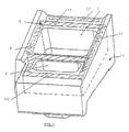
- Fig. 1 gives a schematic illustration of the ejector carrying the general mark 1 with two pockets 3 and 5 according to the invention, comprising the material reinforcement composite identified by the general reference 6 and represented in hatched lines.
- This composite material is preferably made from an agglomerate of ceramic grains with alumina-zirconia base. These ceramic grains are conventionally manufactured, by electro-fusion, by sintering, by thermal spraying or by any other process for merging the two constituents.
- the composite reinforcement structure is performed around the perimeter of the ejector pockets at a minimum distance of 5 mm from the edges of the pockets preventing thus wear of the ejector at the lower edge 9, from the upper edge 11, as well as at the level of the nose 13 and at outlet 15 of the ejector.
- a complementary reinforcement structure (also shown in hatched lines) 17 can be provided in the outlet face of the ejector 1.
- the reinforcement structure composite does not necessarily have to be placed on the entire width, length or depth of the ejector to resist degradation of the structure.
- Figures 2 and 3 show two ejectors of different configuration, one with only one pocket, the other comprising two pockets.
- the geometry of the composite structure is adapted to the geometrical configuration of the ejector, chosen according to the material to be crushed.
- the particular configuration of the composite structure as illustrated was chosen from on the one hand to limit the wear of the whole part of the ejector and on the other hand, allow to realize easily the ejector provided in situ with the structure of reinforcement when the ejector is poured.
- the ejector is therefore formed in the form of a heterogeneous element but without attachments comprising in areas predominantly subject to wear, a reinforcement integrated in the ejector in the form of a structure based on a composite material which is formed from an iron-based alloy (cast iron or steel), on the one hand and ceramic having the property of resistance to wear for the intended uses, on the other hand.
- a reinforcement integrated in the ejector in the form of a structure based on a composite material which is formed from an iron-based alloy (cast iron or steel), on the one hand and ceramic having the property of resistance to wear for the intended uses, on the other hand.
- Figs. 4 and 5 represent a photographs of a two-pocket ejector by condition of the technique, where preferential wear is localized essentially at the nose of the ejector as well as at level of the lower edge of the pockets in contact with the rotary table.
- the life of the reinforced ejector composite is double that obtained with ejectors without this reinforcement.
Landscapes
- Engineering & Computer Science (AREA)
- Food Science & Technology (AREA)
- Crushing And Pulverization Processes (AREA)
- Manufacture Of Alloys Or Alloy Compounds (AREA)
- Crushing And Grinding (AREA)
- Medicinal Preparation (AREA)
- Particle Formation And Scattering Control In Inkjet Printers (AREA)
- Moulds For Moulding Plastics Or The Like (AREA)
- Prostheses (AREA)
Description
L'éjecteur se présente essentiellement sous la forme d'un parallélépipède réalisé généralement en fonte qui est fixé sur la table rotative du concasseur. La face de l'éjecteur qui est dirigée vers l'axe de rotation de la table est appelée le nez de l'éjecteur, tandis que la face parallèle aux enclumes de la cuve cylindrique forme la face de sortie de l'éjecteur.
- La Fig. 1
- représente une vue en perspective d'un éjecteur à deux poches selon l'invention.
- La Fig. 2
- représente une photographie illustrant l'éjecteur à deux poches selon l'invention.
- La Fig. 3
- représente une photographie de l'éjecteur à une seule poche selon l'invention.
- Les Fig. 4 et 5
- représentent deux photographies d'un éjecteur à deux poches selon l'état de la technique, illustrant des endroits d'usure préférentiels.
Claims (5)
- Procédé de fabrication d'un éjecteur à une ou plusieurs poches, destiné à des concasseurs de type centrifuge à axe vertical et ayant une forme essentiellement parallélépipédique, pourvu sur sa face de travail d'une ou plusieurs cavités (3, 5) formant les poches dudit éjecteur (1), toute ou une partie de la périphérie de la ou des poches étant munie d'une structure de renfort (6), caractérisé en ce que ladite structure de renfort comprend un matériau composite lui-même formé d'un alliage à base de fer et de grains de céramique très résistant à l'usure et formé par infiltration de ladite céramique à la coulée de l'éjecteur par le métal liquide servant à former le corps dudit éjecteur.
- Procédé selon la revendication 1, caractérisé en ce que ladite céramique de la structure de renfort est préparée à partir de grains céramiques agglomérés à base d'alumine, de zircone ou d'alumine-zircone.
- Procédé selon la revendication 1, caractérisé en ce que la structure de renfort créée par infiltration n'est réalisée que sur une portion de la largeur ou une portion de la longueur ou une portion de la profondeur de l'éjecteur.
- Procédé selon la revendication 1 ou 2, caractérisé en ce que la structure de renfort est adaptée au nombre, à la taille et à la forme géométrique de la ou des poches de l'éjecteur.
- Procédé selon l'une quelconque des revendications précédentes, caractérisé en ce que la structure de renfort disposée à la périphérie de la ou des poches comprend en outre une structure de renfort complémentaire (17) disposée dans la face de sortie de l'éjecteur.
Applications Claiming Priority (3)
| Application Number | Priority Date | Filing Date | Title |
|---|---|---|---|
| BE9800211 | 1998-03-17 | ||
| BE9800211A BE1011841A3 (fr) | 1998-03-17 | 1998-03-17 | Ejecteur a une ou plusieurs poche(s). |
| PCT/BE1999/000034 WO1999047264A1 (fr) | 1998-03-17 | 1999-03-16 | Ejecteur a une ou plusieurs poches |
Publications (2)
| Publication Number | Publication Date |
|---|---|
| EP1064096A1 EP1064096A1 (fr) | 2001-01-03 |
| EP1064096B1 true EP1064096B1 (fr) | 2003-10-29 |
Family
ID=3891158
Family Applications (1)
| Application Number | Title | Priority Date | Filing Date |
|---|---|---|---|
| EP99911529A Expired - Lifetime EP1064096B1 (fr) | 1998-03-17 | 1999-03-16 | Ejecteur a une ou plusieurs poches |
Country Status (18)
| Country | Link |
|---|---|
| US (1) | US6588692B1 (fr) |
| EP (1) | EP1064096B1 (fr) |
| JP (1) | JP4092077B2 (fr) |
| KR (1) | KR100528303B1 (fr) |
| CN (1) | CN1104287C (fr) |
| AT (1) | ATE252946T1 (fr) |
| AU (1) | AU736079B2 (fr) |
| BE (1) | BE1011841A3 (fr) |
| CA (1) | CA2322861C (fr) |
| CZ (1) | CZ296643B6 (fr) |
| DE (1) | DE69912409T2 (fr) |
| ES (1) | ES2209411T3 (fr) |
| HU (1) | HU226992B1 (fr) |
| PL (1) | PL194714B1 (fr) |
| PT (1) | PT1064096E (fr) |
| SK (1) | SK285790B6 (fr) |
| TR (1) | TR200002676T2 (fr) |
| WO (1) | WO1999047264A1 (fr) |
Families Citing this family (9)
| Publication number | Priority date | Publication date | Assignee | Title |
|---|---|---|---|---|
| PT930948E (pt) | 1996-10-01 | 2001-01-31 | Magotteaux Int | Peca de desgaste composita |
| ES2235923T3 (es) | 2000-08-02 | 2005-07-16 | Magotteaux International S.A. | Impactador destinado a unos trituradores centrifugos de eje vertical y procedimiento de produccion. |
| NL1019297C1 (nl) * | 2001-06-26 | 2003-01-07 | Johannes Petrus Andreas Zanden | Versnellingsblok met verstevigingsdeel. |
| CN1275723C (zh) * | 2001-12-04 | 2006-09-20 | 马格托国际股份有限公司 | 具有增强耐磨性的铸型部件 |
| KR100466868B1 (ko) * | 2004-05-31 | 2005-01-24 | 허홍순 | 분배부재, 이를 갖는 수직축 임팩트 크러셔 및 분배부재의제조 방법 |
| US20070007376A1 (en) * | 2005-07-07 | 2007-01-11 | Condon Gary J | Wear-resistant anvil and impact rock crusher machine using such wear-resistant anvil |
| US8147980B2 (en) | 2006-11-01 | 2012-04-03 | Aia Engineering, Ltd. | Wear-resistant metal matrix ceramic composite parts and methods of manufacturing thereof |
| US8241761B2 (en) * | 2007-08-15 | 2012-08-14 | Mikhail Garber | Abrasion and impact resistant composite castings for working in condition of wear and high dynamic loads |
| DE112017003304T5 (de) | 2016-06-29 | 2019-03-14 | Superior Industries, Inc. | Prallbrecher mit vertikaler Welle |
Family Cites Families (8)
| Publication number | Priority date | Publication date | Assignee | Title |
|---|---|---|---|---|
| US3044720A (en) * | 1960-09-30 | 1962-07-17 | Thomas E Bridgewater | Impact crushing apparatus |
| US3149793A (en) * | 1962-07-30 | 1964-09-22 | Adams Engr Co | Impeller shoe |
| US3346203A (en) * | 1965-07-12 | 1967-10-10 | Bath Iron Works Corp | Impeller for centrifugal pulverizer |
| ZA844074B (en) * | 1983-05-30 | 1986-04-30 | Vickers Australia Ltd | Abrasion resistant materials |
| US4787564A (en) * | 1984-11-23 | 1988-11-29 | Garry Tucker | Rock-crusher shoe |
| FR2577445B1 (fr) * | 1985-02-15 | 1988-05-27 | Framatome Sa | Dispositif de projection de particules solides pour broyeur centrifuge sous vide |
| GB8727231D0 (en) * | 1987-11-20 | 1987-12-23 | Impact Technology Ltd | Machine for comminuting materials |
| US6033791A (en) * | 1997-04-04 | 2000-03-07 | Smith And Stout Research And Development, Inc. | Wear resistant, high impact, iron alloy member and method of making the same |
-
1998
- 1998-03-17 BE BE9800211A patent/BE1011841A3/fr not_active IP Right Cessation
-
1999
- 1999-03-16 HU HU0100924A patent/HU226992B1/hu not_active IP Right Cessation
- 1999-03-16 WO PCT/BE1999/000034 patent/WO1999047264A1/fr active IP Right Grant
- 1999-03-16 DE DE69912409T patent/DE69912409T2/de not_active Expired - Lifetime
- 1999-03-16 SK SK1386-2000A patent/SK285790B6/sk not_active IP Right Cessation
- 1999-03-16 TR TR2000/02676T patent/TR200002676T2/xx unknown
- 1999-03-16 PL PL99343027A patent/PL194714B1/pl not_active IP Right Cessation
- 1999-03-16 CA CA002322861A patent/CA2322861C/fr not_active Expired - Fee Related
- 1999-03-16 AU AU52643/99A patent/AU736079B2/en not_active Ceased
- 1999-03-16 CN CN99804052A patent/CN1104287C/zh not_active Expired - Fee Related
- 1999-03-16 ES ES99911529T patent/ES2209411T3/es not_active Expired - Lifetime
- 1999-03-16 PT PT99911529T patent/PT1064096E/pt unknown
- 1999-03-16 JP JP2000536488A patent/JP4092077B2/ja not_active Expired - Fee Related
- 1999-03-16 EP EP99911529A patent/EP1064096B1/fr not_active Expired - Lifetime
- 1999-03-16 CZ CZ20003140A patent/CZ296643B6/cs not_active IP Right Cessation
- 1999-03-16 AT AT99911529T patent/ATE252946T1/de active
- 1999-03-16 KR KR10-2000-7010202A patent/KR100528303B1/ko not_active IP Right Cessation
-
2000
- 2000-09-15 US US09/663,244 patent/US6588692B1/en not_active Expired - Fee Related
Also Published As
| Publication number | Publication date |
|---|---|
| PL343027A1 (en) | 2001-07-30 |
| ATE252946T1 (de) | 2003-11-15 |
| BE1011841A3 (fr) | 2000-02-01 |
| SK285790B6 (sk) | 2007-08-02 |
| PT1064096E (pt) | 2004-03-31 |
| CZ296643B6 (cs) | 2006-05-17 |
| JP4092077B2 (ja) | 2008-05-28 |
| CA2322861C (fr) | 2008-05-27 |
| CZ20003140A3 (cs) | 2001-03-14 |
| DE69912409T2 (de) | 2004-07-22 |
| EP1064096A1 (fr) | 2001-01-03 |
| DE69912409D1 (de) | 2003-12-04 |
| CN1104287C (zh) | 2003-04-02 |
| CN1293595A (zh) | 2001-05-02 |
| SK13862000A3 (sk) | 2001-07-10 |
| KR20010041899A (ko) | 2001-05-25 |
| US6588692B1 (en) | 2003-07-08 |
| CA2322861A1 (fr) | 1999-09-23 |
| HU226992B1 (en) | 2010-04-28 |
| WO1999047264A1 (fr) | 1999-09-23 |
| JP2002506721A (ja) | 2002-03-05 |
| PL194714B1 (pl) | 2007-06-29 |
| HUP0100924A3 (en) | 2002-02-28 |
| TR200002676T2 (tr) | 2001-02-21 |
| HUP0100924A2 (hu) | 2001-06-28 |
| ES2209411T3 (es) | 2004-06-16 |
| KR100528303B1 (ko) | 2005-11-15 |
| AU5264399A (en) | 1999-10-11 |
| AU736079B2 (en) | 2001-07-26 |
Similar Documents
| Publication | Publication Date | Title |
|---|---|---|
| BE1012097A3 (fr) | Element de coupe superdur a reduction de contrainte. | |
| BE1013044A5 (fr) | Elements de coupe superabrasifs a contrainte de traction residuelle reduite pour le forage de terre et trepans de forage comportant de tels elements | |
| BE1012649A5 (fr) | Element de coupe superabrasif avec chanfrein plan supporte par un contrefort et trepans de forage equipes d'un tel element. | |
| BE1014915A5 (fr) | Structure de forage de formations souterraines. | |
| BE1013071A5 (fr) | Element de coupe a surface de contact superabrasive controlee, trepans de forage ainsi equipes et procedes de forage. | |
| BE1010218A5 (fr) | Element de coupe en diamant polycristallin. | |
| BE1012648A5 (fr) | Elements de coupe superabrasifs a structure alignee par rapport a la charge. | |
| BE1011666A5 (fr) | Goujon pour element de coupe de trepan de forage. | |
| EP1064096B1 (fr) | Ejecteur a une ou plusieurs poches | |
| EP3134212B1 (fr) | Galet de broyage comportant des inserts a massivite elevee | |
| EP0476496B1 (fr) | Procédé de fabrication d'une pièce de fonderie bimétallique et pièce d'usure réalisée par ce procédé | |
| FR2502235A1 (fr) | Element de coupe pour trepan de forage rotatif pour forages profonds dans des formations geologiques | |
| CA2091888A1 (fr) | Dent pour outil d'excavation | |
| FR2667804A1 (fr) | Plaque a surface antiabrasion, et procede pour sa realisation. | |
| EP1570905A1 (fr) | Galets de broyage pour broyeur vertical | |
| EP3525934B1 (fr) | Galet de broyage | |
| WO1998031467A1 (fr) | Insert pour pieces d'usure composites, procede de fabrication d'une piece d'usure a l'aide de tels inserts et piece d'usure ainsi realisee | |
| FR2735522A1 (fr) | Taillant d'outil de forage monobloc | |
| LU88246A1 (fr) | Procédé de fabrication de pièces d'usure composite et pièces réalisées par ce procédé | |
| EP1305116B1 (fr) | Impacteur destine a des concasseurs centrifuges a axe vertical et procede de production | |
| FR2799145A3 (fr) | Scie abrasive | |
| BE1027444B1 (fr) | Piece d'usure composite | |
| FR3011197A1 (fr) | Revêtement resistant a l'usure | |
| BE1014945A3 (fr) | Structure de coupe pour du forage de formations souterraines. | |
| JP2004249166A (ja) | 刃体とその製造方法 |
Legal Events
| Date | Code | Title | Description |
|---|---|---|---|
| PUAI | Public reference made under article 153(3) epc to a published international application that has entered the european phase |
Free format text: ORIGINAL CODE: 0009012 |
|
| 17P | Request for examination filed |
Effective date: 20000901 |
|
| AK | Designated contracting states |
Kind code of ref document: A1 Designated state(s): AT BE CH DE ES FR GB IT LI PT |
|
| 17Q | First examination report despatched |
Effective date: 20020729 |
|
| GRAH | Despatch of communication of intention to grant a patent |
Free format text: ORIGINAL CODE: EPIDOS IGRA |
|
| GRAH | Despatch of communication of intention to grant a patent |
Free format text: ORIGINAL CODE: EPIDOS IGRA |
|
| GRAA | (expected) grant |
Free format text: ORIGINAL CODE: 0009210 |
|
| AK | Designated contracting states |
Kind code of ref document: B1 Designated state(s): AT BE CH DE ES FR GB IT LI PT |
|
| REG | Reference to a national code |
Ref country code: GB Ref legal event code: FG4D Free format text: NOT ENGLISH |
|
| REG | Reference to a national code |
Ref country code: CH Ref legal event code: EP |
|
| REG | Reference to a national code |
Ref country code: CH Ref legal event code: NV Representative=s name: CRONIN INTELLECTUAL PROPERTY |
|
| REF | Corresponds to: |
Ref document number: 69912409 Country of ref document: DE Date of ref document: 20031204 Kind code of ref document: P |
|
| GBT | Gb: translation of ep patent filed (gb section 77(6)(a)/1977) |
Effective date: 20031119 |
|
| REG | Reference to a national code |
Ref country code: PT Ref legal event code: SC4A Free format text: AVAILABILITY OF NATIONAL TRANSLATION Effective date: 20040129 |
|
| REG | Reference to a national code |
Ref country code: ES Ref legal event code: FG2A Ref document number: 2209411 Country of ref document: ES Kind code of ref document: T3 |
|
| PLBE | No opposition filed within time limit |
Free format text: ORIGINAL CODE: 0009261 |
|
| STAA | Information on the status of an ep patent application or granted ep patent |
Free format text: STATUS: NO OPPOSITION FILED WITHIN TIME LIMIT |
|
| 26N | No opposition filed |
Effective date: 20040730 |
|
| REG | Reference to a national code |
Ref country code: CH Ref legal event code: PCAR Free format text: CRONIN INTELLECTUAL PROPERTY;CHEMIN DE PRECOSSY 31;1260 NYON (CH) |
|
| PGFP | Annual fee paid to national office [announced via postgrant information from national office to epo] |
Ref country code: IT Payment date: 20120224 Year of fee payment: 14 |
|
| PGFP | Annual fee paid to national office [announced via postgrant information from national office to epo] |
Ref country code: ES Payment date: 20130305 Year of fee payment: 15 Ref country code: CH Payment date: 20130226 Year of fee payment: 15 Ref country code: DE Payment date: 20130221 Year of fee payment: 15 Ref country code: GB Payment date: 20130228 Year of fee payment: 15 |
|
| PGFP | Annual fee paid to national office [announced via postgrant information from national office to epo] |
Ref country code: BE Payment date: 20130222 Year of fee payment: 15 |
|
| PGFP | Annual fee paid to national office [announced via postgrant information from national office to epo] |
Ref country code: PT Payment date: 20130314 Year of fee payment: 15 Ref country code: AT Payment date: 20130225 Year of fee payment: 15 |
|
| PGFP | Annual fee paid to national office [announced via postgrant information from national office to epo] |
Ref country code: FR Payment date: 20130429 Year of fee payment: 15 |
|
| REG | Reference to a national code |
Ref country code: PT Ref legal event code: MM4A Free format text: LAPSE DUE TO NON-PAYMENT OF FEES Effective date: 20140916 |
|
| REG | Reference to a national code |
Ref country code: DE Ref legal event code: R119 Ref document number: 69912409 Country of ref document: DE |
|
| REG | Reference to a national code |
Ref country code: CH Ref legal event code: PL |
|
| REG | Reference to a national code |
Ref country code: AT Ref legal event code: MM01 Ref document number: 252946 Country of ref document: AT Kind code of ref document: T Effective date: 20140316 |
|
| GBPC | Gb: european patent ceased through non-payment of renewal fee |
Effective date: 20140316 |
|
| REG | Reference to a national code |
Ref country code: FR Ref legal event code: ST Effective date: 20141128 |
|
| PG25 | Lapsed in a contracting state [announced via postgrant information from national office to epo] |
Ref country code: PT Free format text: LAPSE BECAUSE OF NON-PAYMENT OF DUE FEES Effective date: 20140916 |
|
| REG | Reference to a national code |
Ref country code: DE Ref legal event code: R119 Ref document number: 69912409 Country of ref document: DE Effective date: 20141001 |
|
| PG25 | Lapsed in a contracting state [announced via postgrant information from national office to epo] |
Ref country code: GB Free format text: LAPSE BECAUSE OF NON-PAYMENT OF DUE FEES Effective date: 20140316 Ref country code: CH Free format text: LAPSE BECAUSE OF NON-PAYMENT OF DUE FEES Effective date: 20140331 Ref country code: DE Free format text: LAPSE BECAUSE OF NON-PAYMENT OF DUE FEES Effective date: 20141001 Ref country code: LI Free format text: LAPSE BECAUSE OF NON-PAYMENT OF DUE FEES Effective date: 20140331 Ref country code: FR Free format text: LAPSE BECAUSE OF NON-PAYMENT OF DUE FEES Effective date: 20140331 |
|
| PG25 | Lapsed in a contracting state [announced via postgrant information from national office to epo] |
Ref country code: AT Free format text: LAPSE BECAUSE OF NON-PAYMENT OF DUE FEES Effective date: 20140316 |
|
| PG25 | Lapsed in a contracting state [announced via postgrant information from national office to epo] |
Ref country code: IT Free format text: LAPSE BECAUSE OF NON-PAYMENT OF DUE FEES Effective date: 20140316 |
|
| PG25 | Lapsed in a contracting state [announced via postgrant information from national office to epo] |
Ref country code: ES Free format text: LAPSE BECAUSE OF NON-PAYMENT OF DUE FEES Effective date: 20140317 |
|
| PG25 | Lapsed in a contracting state [announced via postgrant information from national office to epo] |
Ref country code: BE Free format text: LAPSE BECAUSE OF NON-PAYMENT OF DUE FEES Effective date: 20140331 |