EP1063408B1 - Zylinderkopf - Google Patents
Zylinderkopf Download PDFInfo
- Publication number
- EP1063408B1 EP1063408B1 EP00113234A EP00113234A EP1063408B1 EP 1063408 B1 EP1063408 B1 EP 1063408B1 EP 00113234 A EP00113234 A EP 00113234A EP 00113234 A EP00113234 A EP 00113234A EP 1063408 B1 EP1063408 B1 EP 1063408B1
- Authority
- EP
- European Patent Office
- Prior art keywords
- spark plug
- cylinder head
- plug seat
- sleeve
- diameter
- Prior art date
- Legal status (The legal status is an assumption and is not a legal conclusion. Google has not performed a legal analysis and makes no representation as to the accuracy of the status listed.)
- Expired - Lifetime
Links
- 238000002485 combustion reaction Methods 0.000 claims description 16
- 238000000034 method Methods 0.000 claims description 10
- 239000000463 material Substances 0.000 claims description 5
- 150000001875 compounds Chemical class 0.000 claims 2
- 238000007789 sealing Methods 0.000 claims 2
- 239000000565 sealant Substances 0.000 abstract description 7
- 238000004519 manufacturing process Methods 0.000 description 6
- 239000002826 coolant Substances 0.000 description 4
- 241000209035 Ilex Species 0.000 description 3
- 238000005520 cutting process Methods 0.000 description 2
- 230000006378 damage Effects 0.000 description 2
- 230000000694 effects Effects 0.000 description 2
- 238000010438 heat treatment Methods 0.000 description 2
- 230000036316 preload Effects 0.000 description 2
- 101100008049 Caenorhabditis elegans cut-5 gene Proteins 0.000 description 1
- 208000032544 Cicatrix Diseases 0.000 description 1
- XAGFODPZIPBFFR-UHFFFAOYSA-N aluminium Chemical compound [Al] XAGFODPZIPBFFR-UHFFFAOYSA-N 0.000 description 1
- 229910052782 aluminium Inorganic materials 0.000 description 1
- 230000001419 dependent effect Effects 0.000 description 1
- 238000003754 machining Methods 0.000 description 1
- 238000003801 milling Methods 0.000 description 1
- 229920001296 polysiloxane Polymers 0.000 description 1
- 230000002028 premature Effects 0.000 description 1
- 230000002035 prolonged effect Effects 0.000 description 1
- 238000009419 refurbishment Methods 0.000 description 1
- 231100000241 scar Toxicity 0.000 description 1
- 230000037387 scars Effects 0.000 description 1
- 238000003756 stirring Methods 0.000 description 1
- 239000013585 weight reducing agent Substances 0.000 description 1
Images

Classifications
-
- F—MECHANICAL ENGINEERING; LIGHTING; HEATING; WEAPONS; BLASTING
- F02—COMBUSTION ENGINES; HOT-GAS OR COMBUSTION-PRODUCT ENGINE PLANTS
- F02F—CYLINDERS, PISTONS OR CASINGS, FOR COMBUSTION ENGINES; ARRANGEMENTS OF SEALINGS IN COMBUSTION ENGINES
- F02F1/00—Cylinders; Cylinder heads
- F02F1/24—Cylinder heads
- F02F1/26—Cylinder heads having cooling means
- F02F1/36—Cylinder heads having cooling means for liquid cooling
- F02F1/38—Cylinder heads having cooling means for liquid cooling the cylinder heads being of overhead valve type
-
- F—MECHANICAL ENGINEERING; LIGHTING; HEATING; WEAPONS; BLASTING
- F02—COMBUSTION ENGINES; HOT-GAS OR COMBUSTION-PRODUCT ENGINE PLANTS
- F02F—CYLINDERS, PISTONS OR CASINGS, FOR COMBUSTION ENGINES; ARRANGEMENTS OF SEALINGS IN COMBUSTION ENGINES
- F02F1/00—Cylinders; Cylinder heads
- F02F1/24—Cylinder heads
- F02F1/242—Arrangement of spark plugs or injectors
-
- F—MECHANICAL ENGINEERING; LIGHTING; HEATING; WEAPONS; BLASTING
- F02—COMBUSTION ENGINES; HOT-GAS OR COMBUSTION-PRODUCT ENGINE PLANTS
- F02F—CYLINDERS, PISTONS OR CASINGS, FOR COMBUSTION ENGINES; ARRANGEMENTS OF SEALINGS IN COMBUSTION ENGINES
- F02F1/00—Cylinders; Cylinder heads
- F02F1/24—Cylinder heads
- F02F1/42—Shape or arrangement of intake or exhaust channels in cylinder heads
- F02F1/4214—Shape or arrangement of intake or exhaust channels in cylinder heads specially adapted for four or more valves per cylinder
-
- F—MECHANICAL ENGINEERING; LIGHTING; HEATING; WEAPONS; BLASTING
- F02—COMBUSTION ENGINES; HOT-GAS OR COMBUSTION-PRODUCT ENGINE PLANTS
- F02B—INTERNAL-COMBUSTION PISTON ENGINES; COMBUSTION ENGINES IN GENERAL
- F02B1/00—Engines characterised by fuel-air mixture compression
- F02B1/02—Engines characterised by fuel-air mixture compression with positive ignition
- F02B1/04—Engines characterised by fuel-air mixture compression with positive ignition with fuel-air mixture admission into cylinder
-
- F—MECHANICAL ENGINEERING; LIGHTING; HEATING; WEAPONS; BLASTING
- F02—COMBUSTION ENGINES; HOT-GAS OR COMBUSTION-PRODUCT ENGINE PLANTS
- F02B—INTERNAL-COMBUSTION PISTON ENGINES; COMBUSTION ENGINES IN GENERAL
- F02B2275/00—Other engines, components or details, not provided for in other groups of this subclass
- F02B2275/18—DOHC [Double overhead camshaft]
-
- F—MECHANICAL ENGINEERING; LIGHTING; HEATING; WEAPONS; BLASTING
- F02—COMBUSTION ENGINES; HOT-GAS OR COMBUSTION-PRODUCT ENGINE PLANTS
- F02F—CYLINDERS, PISTONS OR CASINGS, FOR COMBUSTION ENGINES; ARRANGEMENTS OF SEALINGS IN COMBUSTION ENGINES
- F02F1/00—Cylinders; Cylinder heads
- F02F1/24—Cylinder heads
- F02F2001/244—Arrangement of valve stems in cylinder heads
- F02F2001/245—Arrangement of valve stems in cylinder heads the valve stems being orientated at an angle with the cylinder axis
Definitions
- the invention relates to a cutting device for sheets with at least
- the invention relates to a cylinder head of an internal combustion engine according to the preamble of claim 1.
- Such generic cylinder heads are in the prior art For example, from DE 36 01 274 C2, where a cylinder head with several integrally molded spark plug tubes for receiving of spark plugs is described.
- the cylinder head of internal combustion engines seals the working space from the cylinder and transfers part of it during combustion resulting heat energy to the circulating in the cylinder head Coolant, so as to limit the component temperatures in total.
- the cylinder head becomes mechanical due to preload and gas forces claimed and thermally stressed by the combustion.
- the Preload forces of the cylinder head stir with the screw connection the cylinder block, while the gas forces through the combustion caused in the combustion chamber, which therefore also for the thermal Heating the components are responsible.
- the cylinder head is also crucial for the gas exchange of Responsible for combustion and takes the inlet and Exhaust valves and gasoline engines or gas-powered Diesel engines on the spark plug of each cylinder.
- valves each out a valve head and a valve stem, lie sealingly a valve seat, which is incorporated or inserted into the cylinder head is. Downstream of the valve head are the respective inlet or exhaust ports of the engine.
- valves To prevent leaks in the valve seat caused by one-sided wear reinforced valve areas arise, prevent, are often rotatable on engines of known types, the valves arranged so that they make a small rotational movement with each stroke, which usually occurs when opening the valve.
- valves do not seal one hundred percent, because, for example, the Valve center axis as a result of existing manufacturing or assembly inaccuracies lies outside the center axis of the valve seat ring, So an offset exists or the valve seat is damaged.
- valve seats in the cylinder head For larger wear or damage such as scars or impact points is a regrinding or milling of the valve seats in the cylinder head required. In extreme cases, the valve and the valve seat ring be replaced. This is not only costly, but also elaborate.
- the spark plug tube is a receiving opening for the spark plug of the engine and is thus on each cylinder head necessary, in which a spark plug is present.
- the spark plug tube may consist of a deviating from the cylinder head material, However, it is usually directly in the production of the cylinder head incorporated in the form of a hole or recess in this. It allows the inclusion of the spark plugs or their Accessibility, which is why it also has an opening on one side got to.
- valve seat rings are characterized by the structurally tight Distances between the valves inevitably in the immediate vicinity arranged the thread of the spark plug.
- the individual modules are proportional and have no delay on. They are therefore one hundred percent true to size.
- the valve seat rings deform unevenly and thus forms the cause of so-called "cold stall effect”.
- valves are leaking, the problem of deposits in the Area of leaks to accelerated wear of the Valves and also the valve seat ring leads. Although equalized called effect with uniform heating, so with longer term the engine again, but in the cold start phase occurring increased signs of wear in the valve seat area Overall lead to premature failure of the engine.
- the invention is based on the technical problem, a Cylinder head to develop in which an uneven deformation the valve seat rings is largely avoided.
- a should Procedures are provided that the manufacture of such Cylinder head allows.
- a cylinder head of an internal combustion engine with at least one Spark plug tube (1) per cylinder wherein the spark plug tube a the Combustion chamber of the engine facing end region with a Connecting thread (6) for screwing a spark plug in the Cylinder head (3) and an adjoining to the engine outside opened area with extended diameter (d) has to perform the spark plug tube so that it is transverse to its longitudinal direction is severed.
- a Insert sleeve in the spark plug tube and this sleeve by means of a Permanently elastic sealant in the spark plug tube to attach The permanently elastic sealant allows expansion the cylinder head and the spark plug tube to a limited extent, without the components influencing each other.
- the permanently elastic Sealant for example, on a thermal durable silicone base can be made, thus serves a Compensation of the different deformations of the respective cylinder head areas due to their different thermal expansions.
- the sleeve seals in conjunction with the permanently elastic Seal the severed spark plug tube against leaks from Coolant from, provided at the passage of achenkeitssortder Cavity of the engine block is touched.
- the invention proposes to equip the sleeve with a length, which corresponds to the length of the spark plug tube, so that the Diameter difference is compensated again and therefore no Cross-section reduction in this sensitive area of the cylinder head occurs, possibly causing a destruction of the cylinder head could lead.
- the inventive method consists in the following Process steps. Thereafter, first, the inner diameter of the spark plug tube by a material removing process extended to a diameter larger than the outer diameter the sleeve is. As a material-removing process can machining methods are used, as they are known per se. Subsequently, the spark plug tube is transverse to its longitudinal direction severed what the use of the sleeve in the spark plug tube connects, with the sleeve with the permanently elastic sealant is provided. This permanently elastic sealant also has the Advantage that the tightness of the cylinder head still guaranteed remains, that is, no coolant can escape.
- the inventive method and a cylinder head according to the presented solution can be easily incorporated into the manufacturing cycles of motor vehicles without major changes in the Production processes are necessary.
- the retrofit is old Cylinder heads possible.
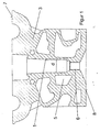
- the central bore with the diameter "d” is the spark plug tube 1 before its extension.
- a thread 6 for fastening the Spark plug introduced in the lower section of the spark plug tube 1, ie in its bottom area.
- the spark plug was in the figures of better clarity not shown.
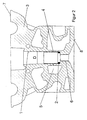
- the sleeve 2 can be inserted into the spark plug tube become. Between sleeve 2 and spark plug tube is also a permanently elastic Introduced sealant.
- the spark plug tube 1 is perpendicular to its longitudinal center axis through a slot 4 divided.
- This slot 4 for example, in the Production of a new cylinder head directly molded or be subsequently introduced by means of a separating tool. He preferably runs circumferentially, but can also only partially be provided.
- the inner diameter of the sleeve 2 was chosen such that the Spark plug can be used by means of a tool and in the Thread can be attached or detached from the thread.
- the cylinder block side is in the figures as the bottom 8 of the cylinder head have been marked while the latter opposite Side is referred to as the top 7.
Landscapes
- Engineering & Computer Science (AREA)
- Chemical & Material Sciences (AREA)
- Combustion & Propulsion (AREA)
- Mechanical Engineering (AREA)
- General Engineering & Computer Science (AREA)
- Cylinder Crankcases Of Internal Combustion Engines (AREA)
- Ignition Installations For Internal Combustion Engines (AREA)
- Valve-Gear Or Valve Arrangements (AREA)
- Valve Device For Special Equipments (AREA)
Description
- Figur 1
- einen Schnitt durch einen Zylinderkopf ohne eine Hülse,
- Figur 2
- einen Schnitt durch einen Zylinderkopf mit einer darin eingesetzten Hülse und
- Figur 3
- einen vergrößerten Ausschnitt des die Hülse aufnehmenden Bereiches.
- 1
- Zündkerzenrohr
- 2
- Hülse
- 3
- Zylinderkopf
- 4
- Schnitt
- 5
- Ausnehmungen
- 6
- Zündkerzenanschlussgewinde
- 7
- Oberseite des Zylinderkopfes
- 8
- Anlagefläche am Motorblock
- d
- Durchmesser des Zündkerzenrohres
- D
- erweiterter Durchmesser des Zündkerzenrohres
Claims (4)
- Zylinderkopf eines Verbrennungsmotors mit mindestens einem Zündkerzenrohr (1) pro Zylinder, wobei das Zündkerzenrohr einen dem Brennraum des Motors zugewandten Endbereich mit einem Anschlussgewinde (6) zur Verschraubung einer Zündkerze in dem Zylinderkopf (3) und einen sich daran anschließenden zur Motoraußenseite geöffneten Bereich mit erweitertem Durchmesser (d) aufweist, dadurch gekennzeichnet, dass das Zündkerzenrohr (1) im Bereich des erweiterten Durchmessers (d) zumindest abschnittsweise durch einen in die Wandung des Zündkerzenrohres eingebrachten Schlitz quer zu seiner Längsrichtung durchtrennt ist.
- Zylinderkopf eines Verbrennungsmotors nach Anspruch 1, dadurch gekennzeichnet, dass in das Zündkerzenrohr (1) eine Hülse (2) und mittels einer dauerelastischen Dichtungsmasse in dem Zündkerzenrohr (1) festgesetzt ist.
- Zylinderkopf eines Verbrennungsmotors nach einem der vorstehend genannten Ansprüche, dadurch gekennzeichnet, dass die Hülse (2) eine dem Zündkerzenrohr (1) annähemd entsprechende Länge aufweist.
- Verfahren zur Herstellung eines Zylinderkopfes nach einem der vorstehend genannten Ansprüche, dadurch gekennzeichnet, dass zunächst der Innendurchmesser (d) des Zündkerzenrohres (1) durch ein materialabtragendes Verfahren auf einen Durchmesser (D) erweitert wird, der größer als der Außendurchmesser der Hülse (2) ist, anschließend das Zündkerzenrohr (1) zumindest abschnittsweise quer zu seiner Längsrichtung durch einen Schlitz durchtrennt und letztlich die mit der dauerelastischen Dichtungsmasse benetzte Hülse (2) in das Zündkerzenrohr (1) eingesetzt und darin justiert wird.
Applications Claiming Priority (2)
| Application Number | Priority Date | Filing Date | Title |
|---|---|---|---|
| DE19928838 | 1999-06-24 | ||
| DE19928838A DE19928838C1 (de) | 1999-06-24 | 1999-06-24 | Zylinderkopf |
Publications (3)
| Publication Number | Publication Date |
|---|---|
| EP1063408A2 EP1063408A2 (de) | 2000-12-27 |
| EP1063408A3 EP1063408A3 (de) | 2001-11-28 |
| EP1063408B1 true EP1063408B1 (de) | 2005-12-07 |
Family
ID=7912308
Family Applications (1)
| Application Number | Title | Priority Date | Filing Date |
|---|---|---|---|
| EP00113234A Expired - Lifetime EP1063408B1 (de) | 1999-06-24 | 2000-06-21 | Zylinderkopf |
Country Status (4)
| Country | Link |
|---|---|
| US (1) | US6675760B1 (de) |
| EP (1) | EP1063408B1 (de) |
| AT (1) | ATE312281T1 (de) |
| DE (2) | DE19928838C1 (de) |
Families Citing this family (6)
| Publication number | Priority date | Publication date | Assignee | Title |
|---|---|---|---|---|
| JP2006009783A (ja) * | 2004-05-21 | 2006-01-12 | Denso Corp | 内燃機関用点火装置 |
| JP5342592B2 (ja) * | 2011-03-31 | 2013-11-13 | 三菱重工業株式会社 | 内燃機関のシリンダ構造 |
| DE102013021547A1 (de) | 2013-12-18 | 2014-07-31 | Daimler Ag | Zylinderkopf für eine Verbrennungskraftmaschine |
| AT16206U1 (de) * | 2017-12-19 | 2019-03-15 | Ge Jenbacher Gmbh & Co Og | Zylinderkopf für eine Brennkraftmaschine |
| GB2602289B (en) | 2020-12-22 | 2023-09-27 | Caterpillar Energy Solutions Gmbh | Improved contact surface of the spark plug jacket |
| US12258929B1 (en) * | 2022-08-05 | 2025-03-25 | Paul J. Gremillion | Method and apparatus for sealing a spark plug well |
Family Cites Families (20)
| Publication number | Priority date | Publication date | Assignee | Title |
|---|---|---|---|---|
| GB119637A (en) * | 1918-06-15 | 1918-10-10 | Motosacoche Sa | Improvements in or relating to Ignition Devices for Water Cooled Explosion Motors. |
| US2234780A (en) * | 1938-12-16 | 1941-03-11 | Gen Motors Corp | Cylinder head construction |
| IT1190176B (it) * | 1985-01-18 | 1988-02-16 | Honda Motor Co Ltd | Motore a combustione interna |
| US5033426A (en) * | 1990-08-22 | 1991-07-23 | Cummins Engine Company, Inc. | Radial combustion seal |
| US5295462A (en) * | 1992-10-16 | 1994-03-22 | Cummins Engine Co., Inc. | Coin insert for the firing deck in an internal combustion engine |
| DE69414557T2 (de) * | 1994-06-15 | 1999-04-01 | Yamaha Hatsudoki K.K., Iwata, Shizuoka | Zylinderkopfanordnung für eine Mehrventil-Brennkraftmaschine mit obenliegender Nockenwelle |
| DE4421057C1 (de) * | 1994-06-16 | 1995-09-14 | Porsche Ag | Zylinderkopfanordnung einer Brennkraftmaschine |
| JP3556725B2 (ja) * | 1995-03-20 | 2004-08-25 | 三菱電機株式会社 | 内燃機関の点火装置 |
| DE19619183C1 (de) * | 1996-05-11 | 1997-07-03 | Porsche Ag | Zylinderkopfanordnung einer Brennkraftmaschine |
| US5979387A (en) * | 1996-11-14 | 1999-11-09 | Strait; William P. | Quick replacement spark plug assembly |
| US5706847A (en) * | 1996-11-14 | 1998-01-13 | Strait; William P. | Quick replacement spark plug assembly |
| US6213109B1 (en) * | 1997-07-04 | 2001-04-10 | Hitachi, Ltd. | Ignition coil for use in internal combustion engine |
| US6138637A (en) * | 1997-09-18 | 2000-10-31 | Daimlerchrysler Ag | Internal combustion engine with direct fuel injection |
| DE29803618U1 (de) * | 1998-03-03 | 1998-06-10 | Kuntschar, Walter, 34466 Wolfhagen | Zylinderkopf beziehungsweise Teil eines Zylinderkopfes eines Verbrennungsmotors mit insbesondere vier Ventilen |
| JPH11329666A (ja) * | 1998-05-15 | 1999-11-30 | Ngk Spark Plug Co Ltd | スパークプラグ |
| US6149336A (en) * | 1998-05-29 | 2000-11-21 | General Motors Corporation | Compliant connector |
| US20010003281A1 (en) * | 1998-06-26 | 2001-06-14 | Kenji Mori | Combustion chamber for direct injection engine |
| JP2000087796A (ja) * | 1998-09-14 | 2000-03-28 | Honda Motor Co Ltd | Dohc式エンジンのシリンダヘッド |
| JP3546753B2 (ja) * | 1999-04-22 | 2004-07-28 | 日産自動車株式会社 | エンジンのシリンダヘッド |
| US6216679B1 (en) * | 1999-07-27 | 2001-04-17 | Delphi Technologies, Inc. | Ignition coil for an internal combustion engine |
-
1999
- 1999-06-24 DE DE19928838A patent/DE19928838C1/de not_active Expired - Fee Related
-
2000
- 2000-06-21 DE DE50011795T patent/DE50011795D1/de not_active Expired - Fee Related
- 2000-06-21 EP EP00113234A patent/EP1063408B1/de not_active Expired - Lifetime
- 2000-06-21 AT AT00113234T patent/ATE312281T1/de not_active IP Right Cessation
- 2000-06-23 US US09/602,260 patent/US6675760B1/en not_active Expired - Fee Related
Also Published As
| Publication number | Publication date |
|---|---|
| US6675760B1 (en) | 2004-01-13 |
| DE19928838C1 (de) | 2001-02-15 |
| DE50011795D1 (de) | 2006-01-12 |
| EP1063408A2 (de) | 2000-12-27 |
| ATE312281T1 (de) | 2005-12-15 |
| EP1063408A3 (de) | 2001-11-28 |
Similar Documents
| Publication | Publication Date | Title |
|---|---|---|
| DE69403843T3 (de) | Ultraleichtes Ventil für Brennkraftmaschine | |
| DE3032253A1 (de) | Verbrennungsmotor | |
| DE3233578C2 (de) | Mehrzylinderbrennkraftmaschine mit nassen Zylinderlaufbüchsen und Einzelzylinderköpfen | |
| EP3428443B1 (de) | Einpresshülse für einen zylinderkopf | |
| DE10114619B4 (de) | Belüftendes Befestigungselement | |
| EP2803827A1 (de) | Metallisches Hohlventil | |
| DE102004028033B4 (de) | Kipphebelachse | |
| EP2832980A1 (de) | Motorgehäuse einer Brennkraftmaschine sowie damit ausgestattete Brennkraftmaschine | |
| DE19928838C1 (de) | Zylinderkopf | |
| DE60217064T2 (de) | Kraftstoff-einspritzdüse | |
| DE3233392A1 (de) | Tellerventil fuer ein gaswechselventil | |
| DE60127478T2 (de) | Zylinderkopf für eine Brennkraftmaschine | |
| DE3414463A1 (de) | Radialkompressor | |
| DE69928619T2 (de) | Direkteingespritze Brennkraftmaschine | |
| DE69109657T2 (de) | Dichtungsvorrichtung zwischen dem zylinderkopf und der zylinderlaufbuchse. | |
| DE202021105982U1 (de) | Druckbehälter | |
| DE19857390C1 (de) | Verfahren zur Herstellung eines Kurbelgehäuses für eine Brennkraftmaschine | |
| DE10149127B4 (de) | Kompressionskolbenring für die Verwendung in einem Verbrennungsmotor und Dieselmotor | |
| EP0971097B1 (de) | Ventil für eine Brennkraftmaschine | |
| DE3249721C2 (de) | Mehrzylinderbrennkraftmaschine mit nassen Zylinderlaufbüchsen und Einzelzylinderköpfen | |
| EP3230591B1 (de) | Gehäuse mit hiergegen gedichtetem zylindrischem einsatz | |
| DE102007037332A1 (de) | Schaltbare Abstützvorrichtung für einen Ventiltrieb einer Brennkraftmaschine | |
| DE102022106130B4 (de) | Kraftfahrzeugkomponente | |
| WO2015036257A1 (de) | Hohlventil, insbesondere für eine brennkraftmaschine | |
| EP3702589B1 (de) | Ventilschaftführung für einen dampfexpander und dampfexpander |
Legal Events
| Date | Code | Title | Description |
|---|---|---|---|
| PUAI | Public reference made under article 153(3) epc to a published international application that has entered the european phase |
Free format text: ORIGINAL CODE: 0009012 |
|
| AK | Designated contracting states |
Kind code of ref document: A2 Designated state(s): AT BE CH CY DE DK ES FI FR GB GR IE IT LI LU MC NL PT SE |
|
| AX | Request for extension of the european patent |
Free format text: AL;LT;LV;MK;RO;SI |
|
| PUAL | Search report despatched |
Free format text: ORIGINAL CODE: 0009013 |
|
| AK | Designated contracting states |
Kind code of ref document: A3 Designated state(s): AT BE CH CY DE DK ES FI FR GB GR IE IT LI LU MC NL PT SE |
|
| AX | Request for extension of the european patent |
Free format text: AL;LT;LV;MK;RO;SI |
|
| RIC1 | Information provided on ipc code assigned before grant |
Free format text: 7F 02F 1/38 A, 7F 02F 1/42 B, 7F 02F 1/24 B |
|
| 17P | Request for examination filed |
Effective date: 20020522 |
|
| AKX | Designation fees paid |
Free format text: AT BE CH CY DE DK ES FI FR GB GR IE IT LI LU MC NL PT SE |
|
| 17Q | First examination report despatched |
Effective date: 20040318 |
|
| GRAP | Despatch of communication of intention to grant a patent |
Free format text: ORIGINAL CODE: EPIDOSNIGR1 |
|
| GRAS | Grant fee paid |
Free format text: ORIGINAL CODE: EPIDOSNIGR3 |
|
| GRAA | (expected) grant |
Free format text: ORIGINAL CODE: 0009210 |
|
| AK | Designated contracting states |
Kind code of ref document: B1 Designated state(s): AT BE CH CY DE DK ES FI FR GB GR IE IT LI LU MC NL PT SE |
|
| PG25 | Lapsed in a contracting state [announced via postgrant information from national office to epo] |
Ref country code: IT Free format text: LAPSE BECAUSE OF FAILURE TO SUBMIT A TRANSLATION OF THE DESCRIPTION OR TO PAY THE FEE WITHIN THE PRESCRIBED TIME-LIMIT;WARNING: LAPSES OF ITALIAN PATENTS WITH EFFECTIVE DATE BEFORE 2007 MAY HAVE OCCURRED AT ANY TIME BEFORE 2007. THE CORRECT EFFECTIVE DATE MAY BE DIFFERENT FROM THE ONE RECORDED. Effective date: 20051207 Ref country code: FI Free format text: LAPSE BECAUSE OF FAILURE TO SUBMIT A TRANSLATION OF THE DESCRIPTION OR TO PAY THE FEE WITHIN THE PRESCRIBED TIME-LIMIT Effective date: 20051207 Ref country code: NL Free format text: LAPSE BECAUSE OF FAILURE TO SUBMIT A TRANSLATION OF THE DESCRIPTION OR TO PAY THE FEE WITHIN THE PRESCRIBED TIME-LIMIT Effective date: 20051207 Ref country code: GB Free format text: LAPSE BECAUSE OF FAILURE TO SUBMIT A TRANSLATION OF THE DESCRIPTION OR TO PAY THE FEE WITHIN THE PRESCRIBED TIME-LIMIT Effective date: 20051207 Ref country code: IE Free format text: LAPSE BECAUSE OF FAILURE TO SUBMIT A TRANSLATION OF THE DESCRIPTION OR TO PAY THE FEE WITHIN THE PRESCRIBED TIME-LIMIT Effective date: 20051207 |
|
| REG | Reference to a national code |
Ref country code: GB Ref legal event code: FG4D Free format text: NOT ENGLISH |
|
| REG | Reference to a national code |
Ref country code: CH Ref legal event code: EP |
|
| REG | Reference to a national code |
Ref country code: IE Ref legal event code: FG4D Free format text: LANGUAGE OF EP DOCUMENT: GERMAN |
|
| REF | Corresponds to: |
Ref document number: 50011795 Country of ref document: DE Date of ref document: 20060112 Kind code of ref document: P |
|
| PG25 | Lapsed in a contracting state [announced via postgrant information from national office to epo] |
Ref country code: GR Free format text: LAPSE BECAUSE OF FAILURE TO SUBMIT A TRANSLATION OF THE DESCRIPTION OR TO PAY THE FEE WITHIN THE PRESCRIBED TIME-LIMIT Effective date: 20060307 Ref country code: SE Free format text: LAPSE BECAUSE OF FAILURE TO SUBMIT A TRANSLATION OF THE DESCRIPTION OR TO PAY THE FEE WITHIN THE PRESCRIBED TIME-LIMIT Effective date: 20060307 Ref country code: DK Free format text: LAPSE BECAUSE OF FAILURE TO SUBMIT A TRANSLATION OF THE DESCRIPTION OR TO PAY THE FEE WITHIN THE PRESCRIBED TIME-LIMIT Effective date: 20060307 |
|
| PG25 | Lapsed in a contracting state [announced via postgrant information from national office to epo] |
Ref country code: ES Free format text: LAPSE BECAUSE OF FAILURE TO SUBMIT A TRANSLATION OF THE DESCRIPTION OR TO PAY THE FEE WITHIN THE PRESCRIBED TIME-LIMIT Effective date: 20060318 |
|
| PG25 | Lapsed in a contracting state [announced via postgrant information from national office to epo] |
Ref country code: PT Free format text: LAPSE BECAUSE OF FAILURE TO SUBMIT A TRANSLATION OF THE DESCRIPTION OR TO PAY THE FEE WITHIN THE PRESCRIBED TIME-LIMIT Effective date: 20060508 |
|
| NLV1 | Nl: lapsed or annulled due to failure to fulfill the requirements of art. 29p and 29m of the patents act | ||
| PG25 | Lapsed in a contracting state [announced via postgrant information from national office to epo] |
Ref country code: MC Free format text: LAPSE BECAUSE OF NON-PAYMENT OF DUE FEES Effective date: 20060630 Ref country code: BE Free format text: LAPSE BECAUSE OF NON-PAYMENT OF DUE FEES Effective date: 20060630 |
|
| GBV | Gb: ep patent (uk) treated as always having been void in accordance with gb section 77(7)/1977 [no translation filed] |
Effective date: 20051207 |
|
| REG | Reference to a national code |
Ref country code: IE Ref legal event code: FD4D |
|
| PLBE | No opposition filed within time limit |
Free format text: ORIGINAL CODE: 0009261 |
|
| STAA | Information on the status of an ep patent application or granted ep patent |
Free format text: STATUS: NO OPPOSITION FILED WITHIN TIME LIMIT |
|
| 26N | No opposition filed |
Effective date: 20060908 |
|
| PG25 | Lapsed in a contracting state [announced via postgrant information from national office to epo] |
Ref country code: DE Free format text: LAPSE BECAUSE OF NON-PAYMENT OF DUE FEES Effective date: 20070103 |
|
| EN | Fr: translation not filed | ||
| PG25 | Lapsed in a contracting state [announced via postgrant information from national office to epo] |
Ref country code: AT Free format text: LAPSE BECAUSE OF NON-PAYMENT OF DUE FEES Effective date: 20060621 |
|
| BERE | Be: lapsed |
Owner name: WESSEL, MARTIN Effective date: 20060630 Owner name: GAHRKEN, OTMAR Effective date: 20060630 |
|
| PG25 | Lapsed in a contracting state [announced via postgrant information from national office to epo] |
Ref country code: FR Free format text: LAPSE BECAUSE OF FAILURE TO SUBMIT A TRANSLATION OF THE DESCRIPTION OR TO PAY THE FEE WITHIN THE PRESCRIBED TIME-LIMIT Effective date: 20070126 |
|
| PG25 | Lapsed in a contracting state [announced via postgrant information from national office to epo] |
Ref country code: LU Free format text: LAPSE BECAUSE OF NON-PAYMENT OF DUE FEES Effective date: 20060621 |
|
| PG25 | Lapsed in a contracting state [announced via postgrant information from national office to epo] |
Ref country code: FR Free format text: LAPSE BECAUSE OF FAILURE TO SUBMIT A TRANSLATION OF THE DESCRIPTION OR TO PAY THE FEE WITHIN THE PRESCRIBED TIME-LIMIT Effective date: 20051207 Ref country code: CY Free format text: LAPSE BECAUSE OF FAILURE TO SUBMIT A TRANSLATION OF THE DESCRIPTION OR TO PAY THE FEE WITHIN THE PRESCRIBED TIME-LIMIT Effective date: 20051207 |
|
| PGFP | Annual fee paid to national office [announced via postgrant information from national office to epo] |
Ref country code: CH Payment date: 20090623 Year of fee payment: 10 |
|
| REG | Reference to a national code |
Ref country code: CH Ref legal event code: PL |
|
| PG25 | Lapsed in a contracting state [announced via postgrant information from national office to epo] |
Ref country code: LI Free format text: LAPSE BECAUSE OF NON-PAYMENT OF DUE FEES Effective date: 20100630 Ref country code: CH Free format text: LAPSE BECAUSE OF NON-PAYMENT OF DUE FEES Effective date: 20100630 |