EP1062145B1 - Actuator device for operating a motorcycle stand and automatically releasable hydraulic valve - Google Patents
Actuator device for operating a motorcycle stand and automatically releasable hydraulic valve Download PDFInfo
- Publication number
- EP1062145B1 EP1062145B1 EP99917825A EP99917825A EP1062145B1 EP 1062145 B1 EP1062145 B1 EP 1062145B1 EP 99917825 A EP99917825 A EP 99917825A EP 99917825 A EP99917825 A EP 99917825A EP 1062145 B1 EP1062145 B1 EP 1062145B1
- Authority
- EP
- European Patent Office
- Prior art keywords
- stand
- chamber
- actuator
- liquid
- actuating member
- Prior art date
- Legal status (The legal status is an assumption and is not a legal conclusion. Google has not performed a legal analysis and makes no representation as to the accuracy of the status listed.)
- Expired - Lifetime
Links
- 239000007788 liquid Substances 0.000 claims description 27
- 238000000034 method Methods 0.000 claims description 2
- 238000009434 installation Methods 0.000 abstract description 3
- 238000006243 chemical reaction Methods 0.000 description 1
- 238000006073 displacement reaction Methods 0.000 description 1
- 239000000463 material Substances 0.000 description 1
Images

Classifications
-
- B—PERFORMING OPERATIONS; TRANSPORTING
- B62—LAND VEHICLES FOR TRAVELLING OTHERWISE THAN ON RAILS
- B62H—CYCLE STANDS; SUPPORTS OR HOLDERS FOR PARKING OR STORING CYCLES; APPLIANCES PREVENTING OR INDICATING UNAUTHORIZED USE OR THEFT OF CYCLES; LOCKS INTEGRAL WITH CYCLES; DEVICES FOR LEARNING TO RIDE CYCLES
- B62H1/00—Supports or stands forming part of or attached to cycles
- B62H1/02—Articulated stands, e.g. in the shape of hinged arms
Definitions
- the present invention relates to the field of the motorcycles industry and more precisely it relates to an actuator device for operating the stand of motorcycles.
- the invention relates to an automatically releasable hydraulic valve, used for operating motorcycles stands.
- Hydraulic stand actuating systems are also known in US-A-4,223,906 and in DE-A-2913429.
- DE'429 document a liquid pressure is created by a pump and operates an hydaulic actuator hinged to the stand.
- Object of the present invention is to provide a device for actuating the stand of motorcycles that can be operated electrohydraulically.
- the stopping means of the outlet mouth as defined in claim 10 comprises a needle that extends from the piston through the second chamber.
- the hydraulic actuator may be an hydraulic cylinder and the actuating member may be a stem that moves between an extended position and a retracted position, the stem being in the retracted position when it is located in the second position. Alternatively the stem is in the retracted position when it is located in the first position.
- the means for allowing the back stroke of the stem in the extended position comprises a pivot with a transversal hole and rotatably connected to the stand, the stem slidingly engaging with the hole and having an enlarged end with respect to the hole, whereby the passage of the stem from the extended position to the retracted position causes the pulling of the pivot and then the pulling of the stand from the rest position to the standing position.
- the hydraulic cylinder comprises a first and a second opening of passage of liquid for operating the movement of the stem between the extended position and the retracted position, resilient means being provided for pushing the stem to the extended position and pushing the liquid out through the first opening.
- the actuator for moving the actuating member from the first to the second position allows the return stroke of the actuating member and the stand, the stand being pivotally connected to the actuating member whereby the actuating member returns to the extended position only when the stand returns to the rest position.
- Actuator 1 has a stem 7 operated by a piston 7a that slides in a cylinder 1a. Piston 7a divides the cylinder 1a into two chambers, 9 and 26, and is biased by a spring 27 present in chamber 26. Chambers 9 and 26 have respectively a first and a second liquid passage mouth 1b and 1c.
- Stem 7 slidingly engages with a pierced pivot 6 rotatably connected to a fork 5 hinged in 8 to frame 2.
- Fork 5 is integral to a stand 4, suitable for holding frame 2 of the motorcycle in a standing position when not running.
- stand 4 is shown in a diagrammatical way, being clear that it has a structure of type known to a man of the art.
- Stand 4 is shown in two positions: a rest position, substantially aligned to frame 2 and indicated with a continuous line, and a position B of stay, substantially orthogonal to frame 2 and indicated with a dotted line
- Spring means are provided, not shown since known in the existing stands, for returning the stand from the position B of support of the vehicle to the rest position A, and that acts on fork 5 of stand 4 biasing its rotation in a clockwise direction.
- Actuator 1 has chamber 9 wherein pressurised oil is delivered through first opening 1b and has stem 7 having at the free end a pawl 10, suitable for abutting against pivot 6, because it is not capable of passing through its hole.
- stem 7 when stand 4 has achieved position B of figure 1, stem 7 returns automatically in the rest position indicated with a dotted line, whereas stand 4 continues to remain in the position B. This is achieved by the automatic emptying of chamber 9, obtained as described below.
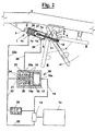
- actuator 1 of fig. 2 a positive displacement pump 12 is shown which, operated by an electrical motor 13, delivers pressurised oil through the delivery duct 15 into a special flow control valve 16 through an inlet mouth 15a.
- Valve 16 comprises a cylinder 16a having a chamber 17 and a chamber 20 separated by a piston 19 having holes 18.
- Chamber 20 has an outlet 21 connected with a suction duct 22 of pump 12, and a side delivery duct 25, through a mouth 25a, for delivering pressurised oil into chamber 9 of actuator 1.
- Piston 19 is pushed towards chamber 17 by a spring 23 and has a needle 24 suitable for engaging in outlet 21 and then stopping it.
- pump 12 delivers pressurised oil into chamber 17 through duct 15.
- the oil does not exit from mouth 25a, since it is not capable of overcoming the load of spring 27 acting on piston 7a of actuator 1.
- the pressurised oil is necessarily delivered through mouth 25a of chamber 20 and through duct 25 into chamber 9 of the actuator cylinder, thus pushing the piston of stem 7 towards chamber 26, compressing spring 27 and, through stem 7, as above described, displacing fork 5 of stand 4 that moves from rest position A to standing position B.
- a safety valve 28 is advantageously provided. Therefore, if after the operation the user does not leave immediately the command button and the electrical motor 13 continues to drive pump 12, the oil pressure rises up to actuating the safety valve 28, suitably adjusted to a pressure higher than the maximum pressure necessary for raising the vehicle. As soon as the user leaves the command button, instead, special valve 16 assures that stem 7 returns always in extended position, allowing a quick return of the stand to the rest position, if desired.
- the actuator has the following advantages:
- valve 16 is integral to pivot 6, and the operation thereof is similar to electromechanical devices.
- valve 16 many advantages still arise by using valve 16 according to the invention, owing to the presence of safety valve 28.
Landscapes
- Engineering & Computer Science (AREA)
- Mechanical Engineering (AREA)
- Actuator (AREA)
- Fluid-Pressure Circuits (AREA)
- Auxiliary Drives, Propulsion Controls, And Safety Devices (AREA)
- Jib Cranes (AREA)
- Axle Suspensions And Sidecars For Cycles (AREA)
- Hydraulic Control Valves For Brake Systems (AREA)
- Fluid-Damping Devices (AREA)
Applications Claiming Priority (3)
| Application Number | Priority Date | Filing Date | Title |
|---|---|---|---|
| ITPI980022 | 1998-03-18 | ||
| IT1998PI000022A IT1306111B1 (it) | 1998-03-18 | 1998-03-18 | Dispositivo attuatore, in particolare per azionamento del cavallettodi motoveicoli, e valvola idraulica di sgancio automatico |
| PCT/EP1999/001816 WO1999047407A1 (en) | 1998-03-18 | 1999-03-18 | Actuator device for operating a motorcycle stand and automatically releasable hydraulic valve |
Publications (2)
| Publication Number | Publication Date |
|---|---|
| EP1062145A1 EP1062145A1 (en) | 2000-12-27 |
| EP1062145B1 true EP1062145B1 (en) | 2003-10-01 |
Family
ID=11394237
Family Applications (1)
| Application Number | Title | Priority Date | Filing Date |
|---|---|---|---|
| EP99917825A Expired - Lifetime EP1062145B1 (en) | 1998-03-18 | 1999-03-18 | Actuator device for operating a motorcycle stand and automatically releasable hydraulic valve |
Country Status (8)
| Country | Link |
|---|---|
| US (1) | US6715282B1 (it) |
| EP (1) | EP1062145B1 (it) |
| JP (1) | JP2002506770A (it) |
| AT (1) | ATE251066T1 (it) |
| DE (1) | DE69911752T2 (it) |
| ES (1) | ES2209425T3 (it) |
| IT (1) | IT1306111B1 (it) |
| WO (1) | WO1999047407A1 (it) |
Families Citing this family (7)
| Publication number | Priority date | Publication date | Assignee | Title |
|---|---|---|---|---|
| EP1254829A1 (en) | 2001-04-30 | 2002-11-06 | Marco Doveri | Actuator device for operating a motorcycle stand |
| ITPI20030069A1 (it) | 2003-09-17 | 2005-03-18 | Marco Doveri | Circuito elettroidraulico semplificato per un attuatore |
| US20100013186A1 (en) * | 2008-07-16 | 2010-01-21 | Markie Alcide G | Powered retractable motorcycle stand |
| US8726622B2 (en) | 2010-12-16 | 2014-05-20 | Cnh Industrial America Llc | Feeder arm safety stand |
| US9598127B2 (en) * | 2014-10-28 | 2017-03-21 | Gogoro Inc. | Side stand |
| CN105460103A (zh) * | 2015-11-20 | 2016-04-06 | 南京金城机械有限公司 | 一种二轮自动车中撑的液压助力装置 |
| US10780931B2 (en) | 2018-05-21 | 2020-09-22 | Ronald Siwicki | Kickstand assembly |
Family Cites Families (8)
| Publication number | Priority date | Publication date | Assignee | Title |
|---|---|---|---|---|
| US2072481A (en) * | 1934-01-27 | 1937-03-02 | Gen Electric | Hydraulic operating mechanism for circuit breakers and the like |
| US3136226A (en) * | 1959-03-06 | 1964-06-09 | Gratzmuller Jean Louis | Control system for hydraulic actuators |
| IT1002768B (it) * | 1974-01-25 | 1976-05-20 | Gigli M | Carrello retrattile automatico per motocicli e simili |
| DE2658056A1 (de) * | 1976-12-22 | 1978-07-06 | Bayerische Motoren Werke Ag | Vorrichtung zum ausschwenken eines an einem motorrad angeordneten kippstaenders |
| DE2913429A1 (de) * | 1979-04-04 | 1980-10-16 | Guenter Fischer | Motorradstaender-hydraulik |
| US5029894A (en) * | 1990-03-30 | 1991-07-09 | Willman David M | Retractable motorcycle stop-support wheels |
| US5118126A (en) * | 1990-08-13 | 1992-06-02 | Yaple Winfred E | Powered motorcycle lift/stand |
| FR2678573A1 (fr) * | 1991-07-02 | 1993-01-08 | Miramond Jacques | Bequille automatique. |
-
1998
- 1998-03-18 IT IT1998PI000022A patent/IT1306111B1/it active
-
1999
- 1999-03-18 JP JP2000536611A patent/JP2002506770A/ja active Pending
- 1999-03-18 EP EP99917825A patent/EP1062145B1/en not_active Expired - Lifetime
- 1999-03-18 WO PCT/EP1999/001816 patent/WO1999047407A1/en not_active Ceased
- 1999-03-18 DE DE69911752T patent/DE69911752T2/de not_active Expired - Lifetime
- 1999-03-18 ES ES99917825T patent/ES2209425T3/es not_active Expired - Lifetime
- 1999-03-18 AT AT99917825T patent/ATE251066T1/de active
-
2000
- 2000-09-18 US US09/664,251 patent/US6715282B1/en not_active Expired - Fee Related
Also Published As
| Publication number | Publication date |
|---|---|
| EP1062145A1 (en) | 2000-12-27 |
| DE69911752T2 (de) | 2004-07-29 |
| JP2002506770A (ja) | 2002-03-05 |
| IT1306111B1 (it) | 2001-05-29 |
| ATE251066T1 (de) | 2003-10-15 |
| US6715282B1 (en) | 2004-04-06 |
| ITPI980022A0 (it) | 1998-03-18 |
| ITPI980022A1 (it) | 1999-09-18 |
| WO1999047407A1 (en) | 1999-09-23 |
| DE69911752D1 (de) | 2003-11-06 |
| ES2209425T3 (es) | 2004-06-16 |
Similar Documents
| Publication | Publication Date | Title |
|---|---|---|
| US7686108B2 (en) | Electrically released parking brake for zero turn radius mower | |
| TW568880B (en) | Hydraulic control apparatus for industrial vehicles | |
| US6701823B2 (en) | Method and device for controlling a lift cylinder, especially of working machines | |
| EP1062145B1 (en) | Actuator device for operating a motorcycle stand and automatically releasable hydraulic valve | |
| DK157095B (da) | Hydrauliksystem med en pumpe med konstant leveringsmaengde | |
| JPH03506012A (ja) | 船舶用エンジンの液圧傾け機能用制御システム | |
| US6679054B2 (en) | Electro-hydraulic actuator of a motorcycle stand | |
| JPH06504005A (ja) | 木材割り装置 | |
| EP1067087A3 (en) | Tilt control device for fork lift truck | |
| US5544381A (en) | Dock leveler hydraulic circuit | |
| EP1516805A2 (en) | Simplified electro-hydraulic circuit for a motorcycle stand actuator | |
| KR20030051853A (ko) | 차체를 기울이기 위한 유압 틸팅 장치 및 이러한 유형의틸팅 장치가 장착된 차량 | |
| US5746291A (en) | Floor conveyor vehicle | |
| EP0072233B1 (en) | Vehicle and hydraulic system with single pump therefor | |
| JPH04321803A (ja) | 油圧装置 | |
| US6314728B1 (en) | Hydraulic door operator | |
| FR2726514A1 (fr) | Dispositif d'embrayage/debrayage de secours pour vehicules utilitaires | |
| US4003601A (en) | Safety apparatus for hydraulic valves in dump body mechanism | |
| JP2589736B2 (ja) | 産業機械の油圧装置 | |
| JP2007139148A (ja) | 作業機の油圧装置 | |
| US4099378A (en) | Blocking valve for power steering for lift trucks | |
| JPS598712B2 (ja) | 弁装置 | |
| JPH08143292A (ja) | シーケンスバルブ及び荷役装置の油圧装置 | |
| NL9401264A (nl) | Hefinrichting. | |
| JPH0135607Y2 (it) |
Legal Events
| Date | Code | Title | Description |
|---|---|---|---|
| PUAI | Public reference made under article 153(3) epc to a published international application that has entered the european phase |
Free format text: ORIGINAL CODE: 0009012 |
|
| 17P | Request for examination filed |
Effective date: 20001017 |
|
| AK | Designated contracting states |
Kind code of ref document: A1 Designated state(s): AT BE CH DE DK ES FI FR GB GR IE IT LI LU NL PT SE |
|
| 17Q | First examination report despatched |
Effective date: 20020322 |
|
| GRAH | Despatch of communication of intention to grant a patent |
Free format text: ORIGINAL CODE: EPIDOS IGRA |
|
| GRAS | Grant fee paid |
Free format text: ORIGINAL CODE: EPIDOSNIGR3 |
|
| GRAA | (expected) grant |
Free format text: ORIGINAL CODE: 0009210 |
|
| AK | Designated contracting states |
Kind code of ref document: B1 Designated state(s): AT BE CH DE DK ES FI FR GB GR IE IT LI LU NL PT SE |
|
| PG25 | Lapsed in a contracting state [announced via postgrant information from national office to epo] |
Ref country code: FI Free format text: LAPSE BECAUSE OF FAILURE TO SUBMIT A TRANSLATION OF THE DESCRIPTION OR TO PAY THE FEE WITHIN THE PRESCRIBED TIME-LIMIT Effective date: 20031001 |
|
| REG | Reference to a national code |
Ref country code: GB Ref legal event code: FG4D |
|
| REG | Reference to a national code |
Ref country code: CH Ref legal event code: EP |
|
| REG | Reference to a national code |
Ref country code: IE Ref legal event code: FG4D |
|
| REF | Corresponds to: |
Ref document number: 69911752 Country of ref document: DE Date of ref document: 20031106 Kind code of ref document: P |
|
| PG25 | Lapsed in a contracting state [announced via postgrant information from national office to epo] |
Ref country code: SE Free format text: LAPSE BECAUSE OF FAILURE TO SUBMIT A TRANSLATION OF THE DESCRIPTION OR TO PAY THE FEE WITHIN THE PRESCRIBED TIME-LIMIT Effective date: 20040101 Ref country code: GR Free format text: LAPSE BECAUSE OF FAILURE TO SUBMIT A TRANSLATION OF THE DESCRIPTION OR TO PAY THE FEE WITHIN THE PRESCRIBED TIME-LIMIT Effective date: 20040101 Ref country code: DK Free format text: LAPSE BECAUSE OF FAILURE TO SUBMIT A TRANSLATION OF THE DESCRIPTION OR TO PAY THE FEE WITHIN THE PRESCRIBED TIME-LIMIT Effective date: 20040101 |
|
| REG | Reference to a national code |
Ref country code: CH Ref legal event code: NV Representative=s name: PATENTANWAELTE BREITER + WIEDMER AG |
|
| PG25 | Lapsed in a contracting state [announced via postgrant information from national office to epo] |
Ref country code: LU Free format text: LAPSE BECAUSE OF NON-PAYMENT OF DUE FEES Effective date: 20040318 Ref country code: IE Free format text: LAPSE BECAUSE OF NON-PAYMENT OF DUE FEES Effective date: 20040318 |
|
| REG | Reference to a national code |
Ref country code: ES Ref legal event code: FG2A Ref document number: 2209425 Country of ref document: ES Kind code of ref document: T3 |
|
| ET | Fr: translation filed | ||
| PLBE | No opposition filed within time limit |
Free format text: ORIGINAL CODE: 0009261 |
|
| STAA | Information on the status of an ep patent application or granted ep patent |
Free format text: STATUS: NO OPPOSITION FILED WITHIN TIME LIMIT |
|
| 26N | No opposition filed |
Effective date: 20040702 |
|
| REG | Reference to a national code |
Ref country code: IE Ref legal event code: MM4A |
|
| PGFP | Annual fee paid to national office [announced via postgrant information from national office to epo] |
Ref country code: NL Payment date: 20070228 Year of fee payment: 9 |
|
| PGFP | Annual fee paid to national office [announced via postgrant information from national office to epo] |
Ref country code: CH Payment date: 20070315 Year of fee payment: 9 |
|
| PGFP | Annual fee paid to national office [announced via postgrant information from national office to epo] |
Ref country code: BE Payment date: 20070320 Year of fee payment: 9 |
|
| REG | Reference to a national code |
Ref country code: CH Ref legal event code: PFA Owner name: DOVERI, MARCO Free format text: DOVERI, MARCO#18, VIA XXIV MAGGIO#I-56025 PONTEDERA (PISA) (IT) -TRANSFER TO- DOVERI, MARCO#18, VIA XXIV MAGGIO#I-56025 PONTEDERA (PISA) (IT) |
|
| PG25 | Lapsed in a contracting state [announced via postgrant information from national office to epo] |
Ref country code: PT Free format text: LAPSE BECAUSE OF NON-PAYMENT OF DUE FEES Effective date: 20040301 |
|
| BERE | Be: lapsed |
Owner name: DOVERI MARCO Effective date: 20080331 |
|
| REG | Reference to a national code |
Ref country code: CH Ref legal event code: PL |
|
| PG25 | Lapsed in a contracting state [announced via postgrant information from national office to epo] |
Ref country code: NL Free format text: LAPSE BECAUSE OF NON-PAYMENT OF DUE FEES Effective date: 20081001 |
|
| NLV4 | Nl: lapsed or anulled due to non-payment of the annual fee |
Effective date: 20081001 |
|
| PG25 | Lapsed in a contracting state [announced via postgrant information from national office to epo] |
Ref country code: LI Free format text: LAPSE BECAUSE OF NON-PAYMENT OF DUE FEES Effective date: 20080331 Ref country code: CH Free format text: LAPSE BECAUSE OF NON-PAYMENT OF DUE FEES Effective date: 20080331 |
|
| PG25 | Lapsed in a contracting state [announced via postgrant information from national office to epo] |
Ref country code: BE Free format text: LAPSE BECAUSE OF NON-PAYMENT OF DUE FEES Effective date: 20080331 |
|
| PGFP | Annual fee paid to national office [announced via postgrant information from national office to epo] |
Ref country code: IT Payment date: 20110328 Year of fee payment: 13 Ref country code: FR Payment date: 20110404 Year of fee payment: 13 Ref country code: AT Payment date: 20110325 Year of fee payment: 13 |
|
| PGFP | Annual fee paid to national office [announced via postgrant information from national office to epo] |
Ref country code: DE Payment date: 20110325 Year of fee payment: 13 Ref country code: GB Payment date: 20110328 Year of fee payment: 13 Ref country code: ES Payment date: 20110426 Year of fee payment: 13 |
|
| GBPC | Gb: european patent ceased through non-payment of renewal fee |
Effective date: 20120318 |
|
| REG | Reference to a national code |
Ref country code: AT Ref legal event code: MM01 Ref document number: 251066 Country of ref document: AT Kind code of ref document: T Effective date: 20120318 |
|
| REG | Reference to a national code |
Ref country code: FR Ref legal event code: ST Effective date: 20121130 |
|
| PG25 | Lapsed in a contracting state [announced via postgrant information from national office to epo] |
Ref country code: FR Free format text: LAPSE BECAUSE OF NON-PAYMENT OF DUE FEES Effective date: 20120402 Ref country code: GB Free format text: LAPSE BECAUSE OF NON-PAYMENT OF DUE FEES Effective date: 20120318 Ref country code: AT Free format text: LAPSE BECAUSE OF NON-PAYMENT OF DUE FEES Effective date: 20120318 |
|
| REG | Reference to a national code |
Ref country code: DE Ref legal event code: R119 Ref document number: 69911752 Country of ref document: DE Effective date: 20121002 |
|
| PG25 | Lapsed in a contracting state [announced via postgrant information from national office to epo] |
Ref country code: IT Free format text: LAPSE BECAUSE OF NON-PAYMENT OF DUE FEES Effective date: 20120318 |
|
| REG | Reference to a national code |
Ref country code: ES Ref legal event code: FD2A Effective date: 20130710 |
|
| PG25 | Lapsed in a contracting state [announced via postgrant information from national office to epo] |
Ref country code: ES Free format text: LAPSE BECAUSE OF NON-PAYMENT OF DUE FEES Effective date: 20120319 |
|
| PG25 | Lapsed in a contracting state [announced via postgrant information from national office to epo] |
Ref country code: DE Free format text: LAPSE BECAUSE OF NON-PAYMENT OF DUE FEES Effective date: 20121002 |