EP1062061B1 - Laminoir a chaud pour fines bandes avec enroulement a grande vitesse de chaque bande - Google Patents
Laminoir a chaud pour fines bandes avec enroulement a grande vitesse de chaque bande Download PDFInfo
- Publication number
- EP1062061B1 EP1062061B1 EP00901321A EP00901321A EP1062061B1 EP 1062061 B1 EP1062061 B1 EP 1062061B1 EP 00901321 A EP00901321 A EP 00901321A EP 00901321 A EP00901321 A EP 00901321A EP 1062061 B1 EP1062061 B1 EP 1062061B1
- Authority
- EP
- European Patent Office
- Prior art keywords
- strip
- rolling mill
- output section
- rollers
- roller
- Prior art date
- Legal status (The legal status is an assumption and is not a legal conclusion. Google has not performed a legal analysis and makes no representation as to the accuracy of the status listed.)
- Expired - Lifetime
Links
- 238000004804 winding Methods 0.000 title claims abstract description 11
- 238000005098 hot rolling Methods 0.000 title claims abstract description 7
- 238000005096 rolling process Methods 0.000 claims abstract description 58
- 239000012530 fluid Substances 0.000 claims description 8
- 238000001816 cooling Methods 0.000 claims description 7
- 238000011144 upstream manufacturing Methods 0.000 claims description 4
- 238000005259 measurement Methods 0.000 description 12
- 210000003128 head Anatomy 0.000 description 6
- 238000012986 modification Methods 0.000 description 4
- 230000004048 modification Effects 0.000 description 4
- 238000004519 manufacturing process Methods 0.000 description 3
- XEEYBQQBJWHFJM-UHFFFAOYSA-N Iron Chemical compound [Fe] XEEYBQQBJWHFJM-UHFFFAOYSA-N 0.000 description 2
- 238000005452 bending Methods 0.000 description 2
- 230000015572 biosynthetic process Effects 0.000 description 2
- 238000005266 casting Methods 0.000 description 2
- 230000000694 effects Effects 0.000 description 2
- 229910000831 Steel Inorganic materials 0.000 description 1
- 230000002411 adverse Effects 0.000 description 1
- 238000007664 blowing Methods 0.000 description 1
- 238000009749 continuous casting Methods 0.000 description 1
- 239000012809 cooling fluid Substances 0.000 description 1
- 239000000498 cooling water Substances 0.000 description 1
- 238000012937 correction Methods 0.000 description 1
- 238000013461 design Methods 0.000 description 1
- 238000001514 detection method Methods 0.000 description 1
- 238000009826 distribution Methods 0.000 description 1
- 230000002349 favourable effect Effects 0.000 description 1
- 210000001061 forehead Anatomy 0.000 description 1
- 238000009434 installation Methods 0.000 description 1
- 229910052742 iron Inorganic materials 0.000 description 1
- 238000005304 joining Methods 0.000 description 1
- 239000002184 metal Substances 0.000 description 1
- 229910052751 metal Inorganic materials 0.000 description 1
- 238000000034 method Methods 0.000 description 1
- 238000003825 pressing Methods 0.000 description 1
- 238000012545 processing Methods 0.000 description 1
- 230000000630 rising effect Effects 0.000 description 1
- 238000000926 separation method Methods 0.000 description 1
- 239000010959 steel Substances 0.000 description 1
- 238000005482 strain hardening Methods 0.000 description 1
- XLYOFNOQVPJJNP-UHFFFAOYSA-N water Substances O XLYOFNOQVPJJNP-UHFFFAOYSA-N 0.000 description 1
Images


Classifications
-
- B—PERFORMING OPERATIONS; TRANSPORTING
- B21—MECHANICAL METAL-WORKING WITHOUT ESSENTIALLY REMOVING MATERIAL; PUNCHING METAL
- B21B—ROLLING OF METAL
- B21B39/00—Arrangements for moving, supporting, or positioning work, or controlling its movement, combined with or arranged in, or specially adapted for use in connection with, metal-rolling mills
- B21B39/02—Feeding or supporting work; Braking or tensioning arrangements, e.g. threading arrangements
- B21B39/12—Arrangement or installation of roller tables in relation to a roll stand
-
- B—PERFORMING OPERATIONS; TRANSPORTING
- B21—MECHANICAL METAL-WORKING WITHOUT ESSENTIALLY REMOVING MATERIAL; PUNCHING METAL
- B21B—ROLLING OF METAL
- B21B38/00—Methods or devices for measuring, detecting or monitoring specially adapted for metal-rolling mills, e.g. position detection, inspection of the product
- B21B38/02—Methods or devices for measuring, detecting or monitoring specially adapted for metal-rolling mills, e.g. position detection, inspection of the product for measuring flatness or profile of strips
Definitions
- the invention relates to the hot rolling of thin strip, i.e. metal strip of a thickness of less than 1 ⁇ 1.5 mm.
- Hot working requires, however, particular measures: for instance the speed of output of the strip must in certain cases be kept below predetermined limits because otherwise the head of the strip might be lifted as a result of air resistance.
- the strip advances too rapidly in the output section of the rolling mill (i.e. the part of the mill which is downstream the last rolling stand), there is a risk that its head might strike the guide rolls on which it is moving: following such impacts, it would be deflected upwards so that a part of the strip would be raised from the roll train as a result of air resistance, thereby making its control and subsequent winding on the reel problematic.
- a continuous rolling technique (also called “endless”), in which a single initial strip is cut at the end of rolling, into sections of predetermined length which are then wound as respective coils.
- the strip is obtained from a bar of multiple weight than that of the final coils to be produced, which may in turn be obtained either by joining smaller bars using conventional roughing plants or by thin slab casting.
- This special equipment generally entails some increase in costs, such that plants for the endless rolling of thin strip can be considered rather expensive.
- JP-A-09192717 discloses a rolling mill according to this state of the art.
- the technical problem underlying this invention is therefore that of providing a hot rolling mill with structural and operational features suitable to overcome the limits of the state of the art described above.
- the invention aims to provide a rolling mill for hot working of thin strip, in which the strip is fed in a controlled manner in order to avoid any risk of its lifting in the case of high speeds; a rolling mill of this type is therefore an alternative to rolling mills of endless type and is able to produce successive batches of strip without the drawbacks described above.
- reference 1 indicates overall the output section of a rolling mill according to the invention, upstream and downstream of which there are disposed finishing stands 2 (known per se) for the final rolling of a strip N.
- the section 1 comprises a series of driven rollers 3 adapted to feed the strip, and a station 4 for the detection of its geometrical characteristics (thickness, shape, width) upstream and downstream of which there are located generators of air jets 5, 6, which will be better described below.
- a cooling station 8 Downstream the first drive unit 7 there is provided a cooling station 8 which, in accordance with a preferred embodiment of the invention, is of the ultra-fast cooling type or UFC; this kind of station, indeed, is able to remove large quantities of heat by supplying relevant flows of cooling fluid and are generally used in the rolling of large thickness plates, in order to improve their mechanical properties (likewise a hardening treatment).
- a second drive unit 9 similar to the first one but with its operating rolls oriented so as to deflect the plane of movement of the strip N towards a winding reel 10, is arranged after the cooling station 8; as can be seen from the accompanying drawings, this winding reel is advantageously disposed above the horizontal feeding direction of the strip coming out from the stands 2. This positioning allows for simple installation on the roll trains of existing plants, without the need for excessive modification of their foundations or of the collection duct for the fluid used to cool the strip.
- the position of the reel could however be different from that described above; for instance it could also be disposed lower with respect to the horizontal feeding direction of the strip, as shown by the dashed line in Fig. 1.
- the reel 10 comprises a spindle 11 wherein the strips arriving one after the other are wound and around which pressure rolls 12 are arranged in a known manner; between the second drive unit 9 and the reel 10 there are disposed guides 13, adapted to direct the head of each strip N towards the spindle 11 on which it is then wound.
- the generators of air jets 5, 6, may take the form of fans or compressors appropriately provided with air supply ducts, or of nozzles supplied with compressed air from the distribution network of the industrial plant in which the rolling mill is located.
- the task of these generators is to exert a pressure on the upper surface of the strip N being fed along the output section of the rolling mill 1, in order to keep it flattened against the rollers way formed by the rollers 3; the air velocity thus has a vertical downwardly facing component (with reference to the drawings).
- the blown air may also have a horizontal velocity component parallel to the surface of the strip and greater than the feeding speed of the latter: the generators 5 and 6 thus direct the air jets in an inclined manner with respect to the strip in order to obtain the effects referred before.
- the rolling mill in which the output section 1 described above is located operates as follows; it should be stressed that the rolling mill structure upstream of this section has not been considered in detail here, since it is of secondary importance for the purposes of understanding the present invention.
- a strip N being processed reaches the output section 1 on the rollers way 3 from which it is caused to advance towards the winding reel 10; at this stage the generators 5, 6 are actuated so that the air jets they produce, keep the strip pressed against the rolls 3.
- the movement of the strip N is thus controlled by the air in order to enable its correct engagement with the first drive unit 7, which helps to feed it in a guided manner; in this respect it should be noted that these units are provided with guide members (not shown) adapted to guide the free end of the strip towards the rolls. It should also be noted that at this stage water is sprayed on the strip in the cooling station 8, thereby helping to hold it pressed against the motor-driven rollers 3 up to the second drive unit 9.
- This unit 9 then deflects the direction of feed of the strip N towards the reel 10; this result is obtained by means of the inclination of its rolls as shown in the drawings, which deflect the strip who is then conveyed by the guides 13 towards the spindle 11 and the pressure rollers 12 so that it can be wound in a manner similar to that normally used in the art.
- the wound strip is then removed from the spindle and the reel is ready to receive a new strip as it arrives; it should be noted in this respect that in the rolling mill of the invention there is a dead time between a strip and the next one, during which the last coil wound can be removed.
- the strip is controlled aerodynamically in the output section 1, by exerting a pressure on it that avoid separation thereof from the roller way; this solution is very efficient and operationally flexible and can be applied in the case of high strip speeds (the speed of the air flow can be adjusted at will to increase or decrease the pressure on the strip).
- the aerodynamic control of the strip according to the teaching of the present invention can therefore be advantageously used in new rolling mill plant and in existing plants as well.
- the air jets may be readily adjusted to improve the control of the strip; for instance, it is possible to adjust the pressure exerted by the air in the direction of the width of the strip so as to curve its section and make it more resistant to longitudinal bending and less sensitive to the destabilising phenomena described above.
- a velocity component of the air parallel to that of feeding the strip is created in this way; as this component is greater than the feeding speed of the strip, it prevents the latter from being lifted since it forces the fore head thereof downwards when it is deflected upwards by the impacts with the rolls 3.
- the horizontal velocity component also makes it possible to avoid exerting an excessive pressure on the strip perpendicular thereto.
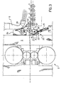
- FIGs. 2 and 3 An example of this is shown in Figs. 2 and 3, wherein the first one shows a number of positions in which it is possible to locate a device for measuring planarity 20 with a tensiometric roller 21 along the output section of Fig. 1, while the second shows a particular embodiment of this roller in greater detail.
- tensiometric rollers are already known in the field of rolling where they are used to measure the planarity of strips, i.e. the presence of undulations in their configuration due to differing deformation between their edge and their centre.
- tensiometric rollers are rollers split longitudinally into cylindrical sections, adjacent to one another and idle with respect to a same axis transverse to the strip; the tensiometric roller is brought into contact with the strip by urging it against the strip and slightly deflecting its run.
- tensiometric rollers are usually disposed between the final rolling stands (i.e., with reference to Fig. 1, between the stands 2 shown therein); this means, however, that the planarity measurement carried out does not take account of the deformation due to the final stand, which must be evaluated using theoretical models and algorithms with all the limitations arising therefrom.
- the time interval that can be used to carry out the planarity measurement and make the necessary corrections to rolling before the strip is wound on the spindle of the reel is around 10 seconds.
- This device may preferably be disposed immediately after the final rolling stand 2 or immediately before the second drive unit 9, as shown in Fig. 2 in which the tensiometric roller is shown respectively by 21' in the former case and by 21" in the latter case.
- the above-mentioned device is formed by the tensiometric roller 21 and by a returning roller 22 which is disposed on the opposite side of the former with respect to the strip N, in a position facing the adjacent motor-driven roll 3.
- both rollers 21 and 22 are spaced from the strip; when the planarity measurement is to be carried out the tensiometric roller 21 is urged upwards and the returning roller 22 downwards so as to bring the strip immediately back into the normal plane of feed.
- the tensiometric roller 21 provides the desired measurement according to its normal operation.
- FIG. 3 A possible embodiment of the device 20 is shown on an enlarged scale in Fig. 3, where reference is made to its position immediately downstream of the final stand 2.
- the roller 3' When it is not necessary to measure the planarity of the strip, the roller 3' is in the position aligned with the other adjacent rollers 3 (as shown in dashed lines in Fig. 3) and the strip slides on it while the tensiometric roller is distanced; vice versa, when this measurement is to be carried out the tensiometric roller 21 is raised causing the frame 23 to oscillate, and at the same time distancing the roller 3'.
- the returning roller 22 is mounted on an arm 28 that also oscillates with respect to a base 29 secured to the bearing structure S of the rolling stand 2.
- planarity measurement device as designed above has the advantage of limiting the wear of the tensiometric roller, thereby ensuring that the measurements provided are reliable; it will be appreciated that this device may also he subject to many variants.
Landscapes
- Engineering & Computer Science (AREA)
- Mechanical Engineering (AREA)
- Metal Rolling (AREA)
- Winding, Rewinding, Material Storage Devices (AREA)
- Laminated Bodies (AREA)
Claims (14)
- Laminoir à chaud pour fines bandes (N), comprenant une section de sortie (1) s'étendant entre une cage de laminoir finale (2) et au moins un enrouleur (10), un chemin de rouleaux commandés (3) disposé longitudinalement par rapport à cette section et le long duquel la bande est avancée, des moyens (5, 6) du type aérodynamique disposés le long de ladite section de sortie pour empêcher la bande d'être soulevée du chemin de rouleaux, caractérisé en ce que
la section de sortie comprend une unité d'entraínement (9) disposée le long du chemin de rouleaux (3) et avant ledit au moins un enrouleur (10), et dans lequel
l'enrouleur (10) est disposé à une hauteur supérieure à celle du chemin de rouleaux (3) et l'unité d'entraínement est d'un type qui peut être orientée pour dévier les bandes (N) vers l'enrouleur. - Laminoir selon la revendication 1, dans lequel les moyens du type aérodynamique comprennent des jets de fluide gazeux dirigés sur la surface supérieure de la bande (N) se déplaçant le long du chemin de rouleaux (3).
- Laminoir selon la revendication 2, dans lequel les jets de fluide gazeux sont inclinés par rapport à la surface supérieure de la bande (N) et la composante de vitesse du fluide parallèle à la vitesse de déplacement de la bande est supérieure à cette dernière.
- Laminoir selon la revendication 3, dans lequel il y a des jets de fluide dirigés perpendiculairement à la surface supérieure de la bande (N) et des jets de fluide dirigés parallèlement à celle-ci, ces derniers ayant une vitesse du fluide supérieure à celle de la bande (N).
- Laminoir selon l'une quelconque des revendications 2 à 4, dans lequel le fluide gazeux est de l'air.
- Laminoir selon l'une quelconque des revendications précédentes, dans lequel les moyens du type aérodynamique adaptés pour empêcher la bande (N) d'être soulevée du chemin de rouleaux (3) comprennent des moyens destinés à produire le vide sous la bande.
- Laminoir selon l'une quelconque des revendications précédentes, dans lequel la section de sortie (1) comprend un poste de refroidissement (8) du type ultra-rapide.
- Laminoir selon la revendication 7, dans lequel la section de sortie (1) comprend un première unité d'entraínement (7) située en amont du poste de refroidissement (8) le long du chemin de rouleaux (3).
- Laminoir selon l'une quelconque des revendications précédentes, dans lequel un dispositif de mesure (20) qui mesure la planéité des bandes (N) et qui comprend un rouleau tensiométrique (21), est agencé dans la section de sortie (1).
- Laminoir selon la revendication 9, dans lequel le dispositif de mesure (20) est disposé au début de la section de sortie (1) dans une position adjacente à la cage de laminoir finale (2).
- Laminoir selon la revendication 9, dans lequel le dispositif de mesure (20) est disposé à la fin de la section de sortie (1) avant la seconde unité d'entraínement (9).
- Laminoir selon la revendication 9, dans lequel le dispositif de mesure (20) est disposé en aval de la seconde unité d'entraínement (9).
- Laminoir selon l'une quelconque des revendications 9, 10 et 11, dans lequel le dispositif de mesure (20) comprend un cadre (23) mobile par rapport à la bande (N) devant être mesurée, sur lequel sont montés le rouleau tensiométrique (21) et un rouleau (3') similaire aux rouleaux (3) qui forment le chemin de rouleaux le long duquel la bande est avancée.
- Laminoir selon l'une quelconque des revendications 9, 10, 11 et 13, dans lequel le rouleau tensiométrique (21) agit sur la surface inférieure de la bande (N) devant être mesurée et le dispositif de mesure (20) comprend en outre un rouleau de retour (22) agissant sur la surface supérieure de la bande, en face d'un rouleau (3) du chemin de rouleaux le long duquel la bande est avancée.
Applications Claiming Priority (3)
| Application Number | Priority Date | Filing Date | Title |
|---|---|---|---|
| ITMI990021 | 1999-01-11 | ||
| IT1999MI000021A IT1306927B1 (it) | 1999-01-11 | 1999-01-11 | Laminatoio a caldo per nastri sottili con avvolgimento ad altavelocita' di nastri singoli |
| PCT/IT2000/000006 WO2000041823A1 (fr) | 1999-01-11 | 2000-01-07 | Laminoir a chaud pour fines bandes avec enroulement a grande vitesse de chaque bande |
Publications (2)
| Publication Number | Publication Date |
|---|---|
| EP1062061A1 EP1062061A1 (fr) | 2000-12-27 |
| EP1062061B1 true EP1062061B1 (fr) | 2004-03-24 |
Family
ID=11381428
Family Applications (1)
| Application Number | Title | Priority Date | Filing Date |
|---|---|---|---|
| EP00901321A Expired - Lifetime EP1062061B1 (fr) | 1999-01-11 | 2000-01-07 | Laminoir a chaud pour fines bandes avec enroulement a grande vitesse de chaque bande |
Country Status (6)
| Country | Link |
|---|---|
| EP (1) | EP1062061B1 (fr) |
| AT (1) | ATE262384T1 (fr) |
| DE (1) | DE60009212T2 (fr) |
| ES (1) | ES2218105T3 (fr) |
| IT (1) | IT1306927B1 (fr) |
| WO (1) | WO2000041823A1 (fr) |
Families Citing this family (4)
| Publication number | Priority date | Publication date | Assignee | Title |
|---|---|---|---|---|
| DE10001074A1 (de) * | 2000-01-13 | 2001-07-19 | Sms Demag Ag | Warmwalzwerk mit Planheitsmeßrolle |
| DE10131850B4 (de) | 2001-06-30 | 2013-04-25 | Sms Siemag Aktiengesellschaft | Dünnbandhaspel mit Planheitsmeßrolle |
| DE102007045698A1 (de) * | 2006-09-25 | 2008-04-03 | Sms Demag Ag | Verfahren und Vorrichtung zum Aufwickeln von Metallbändern auf einen Wickeldorn |
| CN105695727B (zh) * | 2014-11-28 | 2018-01-30 | 宝山钢铁股份有限公司 | 一种钢板在线固溶处理的板形控制方法 |
Family Cites Families (6)
| Publication number | Priority date | Publication date | Assignee | Title |
|---|---|---|---|---|
| DE1153708B (de) * | 1962-06-08 | 1963-09-05 | Schloemann Ag | Foerderrollgang zum Fuehren von duennen Baendern zwischen kontinuierlicher Walzenstrasse und Horizontalhaspel |
| DE3721746A1 (de) * | 1987-07-01 | 1989-01-19 | Schloemann Siemag Ag | Verfahren und vorrichtung zur messung der planheit von walzband in warmbreitbandstrassen |
| JP2763641B2 (ja) * | 1990-01-31 | 1998-06-11 | 日新製鋼株式会社 | ホットランテーブル上のストリップのループ除去制御方法 |
| JPH07323321A (ja) * | 1994-05-31 | 1995-12-12 | Kawasaki Steel Corp | 熱延鋼帯の通板方法 |
| JPH08174031A (ja) * | 1994-12-22 | 1996-07-09 | Kawasaki Steel Corp | 熱間圧延ラインのホットランテーブル上における通板方法 |
| JP3389395B2 (ja) * | 1996-01-10 | 2003-03-24 | 新日本製鐵株式会社 | 熱間圧延におけるストリップ搬送方法および装置 |
-
1999
- 1999-01-11 IT IT1999MI000021A patent/IT1306927B1/it active
-
2000
- 2000-01-07 ES ES00901321T patent/ES2218105T3/es not_active Expired - Lifetime
- 2000-01-07 WO PCT/IT2000/000006 patent/WO2000041823A1/fr active IP Right Grant
- 2000-01-07 AT AT00901321T patent/ATE262384T1/de not_active IP Right Cessation
- 2000-01-07 DE DE60009212T patent/DE60009212T2/de not_active Expired - Lifetime
- 2000-01-07 EP EP00901321A patent/EP1062061B1/fr not_active Expired - Lifetime
Also Published As
| Publication number | Publication date |
|---|---|
| WO2000041823A1 (fr) | 2000-07-20 |
| DE60009212D1 (de) | 2004-04-29 |
| IT1306927B1 (it) | 2001-10-11 |
| EP1062061A1 (fr) | 2000-12-27 |
| ITMI990021A1 (it) | 2000-07-11 |
| ATE262384T1 (de) | 2004-04-15 |
| ES2218105T3 (es) | 2004-11-16 |
| DE60009212T2 (de) | 2004-08-19 |
Similar Documents
| Publication | Publication Date | Title |
|---|---|---|
| JP3929147B2 (ja) | 巻き取り設備 | |
| US20060010679A1 (en) | Apparatus for continuously producing a rolled metal strip from a metal melt | |
| US8459083B2 (en) | Guiding system for a metal strip at a rolling mill outlet | |
| EP2623221A1 (fr) | Dispositif de fabrication et procédé de fabrication d'acier en bandes laminé à chaud | |
| KR100216641B1 (ko) | 열간압연 방법 및 장치 | |
| US6332492B1 (en) | Method to control the axial position of slabs emerging from continuous casting and relative device | |
| EP1062061B1 (fr) | Laminoir a chaud pour fines bandes avec enroulement a grande vitesse de chaque bande | |
| US10583473B2 (en) | Method and device for stabilizing a movement of a rolled metal band on a roller table | |
| JP4114701B2 (ja) | 熱延鋼帯の冷却装置と、その冷却方法および熱延鋼帯の製造方法 | |
| US7318267B2 (en) | Strip production equipment | |
| US20230294153A1 (en) | Straightening machine and method for straightening a metal strip or a flat metal part | |
| CN111229835B (zh) | 一种包角可调式拉伸弯曲矫直机 | |
| US6519990B1 (en) | Method and a device for controlling a rolling mill | |
| JP3004780B2 (ja) | 圧延材の先端曲り矯正方法及び装置並びに熱間薄板圧延設備 | |
| US2796908A (en) | Multiple roller levellers for metal strip | |
| JP7343819B2 (ja) | 曲げ加工装置、鋼矢板の製造設備、曲げ加工方法、及び、鋼矢板の製造方法 | |
| JP7332995B2 (ja) | デフレクターロール及びそのデフレクターロールを用いた鋼板の製造方法 | |
| US5860311A (en) | Method to guide the strip between the stands in a rolling mill finishing train and relative device | |
| KR101353790B1 (ko) | 스트립 장력조정 장치 | |
| EP0032766B1 (fr) | Procédé et dispositif pour laminer des longueurs de barres ou de fils métalliques | |
| JPH08300010A (ja) | 熱間圧延方法および装置 | |
| JP2023503902A (ja) | 圧延装置及び、圧延装置を用いた圧延方法 | |
| CN115591954A (zh) | 一种灵活生产金属带的冷却系统、生产线及生产方法 | |
| KR20170012641A (ko) | 핀치롤 장치 및 이를 포함하는 스트립 권취 설비 | |
| JP2000225410A (ja) | 熱間圧延におけるストリップ搬送方法および装置 |
Legal Events
| Date | Code | Title | Description |
|---|---|---|---|
| PUAI | Public reference made under article 153(3) epc to a published international application that has entered the european phase |
Free format text: ORIGINAL CODE: 0009012 |
|
| 17P | Request for examination filed |
Effective date: 20001002 |
|
| AK | Designated contracting states |
Kind code of ref document: A1 Designated state(s): AT BE CH CY DE DK ES FI FR GB GR IE IT LI LU MC NL PT SE |
|
| 17Q | First examination report despatched |
Effective date: 20030227 |
|
| GRAP | Despatch of communication of intention to grant a patent |
Free format text: ORIGINAL CODE: EPIDOSNIGR1 |
|
| GRAS | Grant fee paid |
Free format text: ORIGINAL CODE: EPIDOSNIGR3 |
|
| GRAA | (expected) grant |
Free format text: ORIGINAL CODE: 0009210 |
|
| AK | Designated contracting states |
Kind code of ref document: B1 Designated state(s): AT BE CH CY DE DK ES FI FR GB GR IE IT LI LU MC NL PT SE |
|
| PG25 | Lapsed in a contracting state [announced via postgrant information from national office to epo] |
Ref country code: LI Free format text: LAPSE BECAUSE OF FAILURE TO SUBMIT A TRANSLATION OF THE DESCRIPTION OR TO PAY THE FEE WITHIN THE PRESCRIBED TIME-LIMIT Effective date: 20040324 Ref country code: NL Free format text: LAPSE BECAUSE OF FAILURE TO SUBMIT A TRANSLATION OF THE DESCRIPTION OR TO PAY THE FEE WITHIN THE PRESCRIBED TIME-LIMIT Effective date: 20040324 Ref country code: CH Free format text: LAPSE BECAUSE OF FAILURE TO SUBMIT A TRANSLATION OF THE DESCRIPTION OR TO PAY THE FEE WITHIN THE PRESCRIBED TIME-LIMIT Effective date: 20040324 Ref country code: AT Free format text: LAPSE BECAUSE OF FAILURE TO SUBMIT A TRANSLATION OF THE DESCRIPTION OR TO PAY THE FEE WITHIN THE PRESCRIBED TIME-LIMIT Effective date: 20040324 Ref country code: FI Free format text: LAPSE BECAUSE OF FAILURE TO SUBMIT A TRANSLATION OF THE DESCRIPTION OR TO PAY THE FEE WITHIN THE PRESCRIBED TIME-LIMIT Effective date: 20040324 |
|
| REG | Reference to a national code |
Ref country code: GB Ref legal event code: FG4D |
|
| REG | Reference to a national code |
Ref country code: CH Ref legal event code: EP |
|
| REG | Reference to a national code |
Ref country code: IE Ref legal event code: FG4D |
|
| REF | Corresponds to: |
Ref document number: 60009212 Country of ref document: DE Date of ref document: 20040429 Kind code of ref document: P |
|
| PG25 | Lapsed in a contracting state [announced via postgrant information from national office to epo] |
Ref country code: GR Free format text: LAPSE BECAUSE OF FAILURE TO SUBMIT A TRANSLATION OF THE DESCRIPTION OR TO PAY THE FEE WITHIN THE PRESCRIBED TIME-LIMIT Effective date: 20040624 Ref country code: DK Free format text: LAPSE BECAUSE OF FAILURE TO SUBMIT A TRANSLATION OF THE DESCRIPTION OR TO PAY THE FEE WITHIN THE PRESCRIBED TIME-LIMIT Effective date: 20040624 Ref country code: SE Free format text: LAPSE BECAUSE OF FAILURE TO SUBMIT A TRANSLATION OF THE DESCRIPTION OR TO PAY THE FEE WITHIN THE PRESCRIBED TIME-LIMIT Effective date: 20040624 |
|
| NLV1 | Nl: lapsed or annulled due to failure to fulfill the requirements of art. 29p and 29m of the patents act | ||
| REG | Reference to a national code |
Ref country code: CH Ref legal event code: PL |
|
| ET | Fr: translation filed | ||
| REG | Reference to a national code |
Ref country code: ES Ref legal event code: FG2A Ref document number: 2218105 Country of ref document: ES Kind code of ref document: T3 |
|
| PLBI | Opposition filed |
Free format text: ORIGINAL CODE: 0009260 |
|
| PG25 | Lapsed in a contracting state [announced via postgrant information from national office to epo] |
Ref country code: IE Free format text: LAPSE BECAUSE OF NON-PAYMENT OF DUE FEES Effective date: 20050107 Ref country code: LU Free format text: LAPSE BECAUSE OF NON-PAYMENT OF DUE FEES Effective date: 20050107 Ref country code: CY Free format text: LAPSE BECAUSE OF FAILURE TO SUBMIT A TRANSLATION OF THE DESCRIPTION OR TO PAY THE FEE WITHIN THE PRESCRIBED TIME-LIMIT Effective date: 20050107 |
|
| PLAX | Notice of opposition and request to file observation + time limit sent |
Free format text: ORIGINAL CODE: EPIDOSNOBS2 |
|
| PG25 | Lapsed in a contracting state [announced via postgrant information from national office to epo] |
Ref country code: MC Free format text: LAPSE BECAUSE OF NON-PAYMENT OF DUE FEES Effective date: 20050131 |
|
| 26 | Opposition filed |
Opponent name: SIEMENSABTEILUNG: CT IP TS Effective date: 20041213 |
|
| PLAX | Notice of opposition and request to file observation + time limit sent |
Free format text: ORIGINAL CODE: EPIDOSNOBS2 |
|
| PLBB | Reply of patent proprietor to notice(s) of opposition received |
Free format text: ORIGINAL CODE: EPIDOSNOBS3 |
|
| REG | Reference to a national code |
Ref country code: IE Ref legal event code: MM4A |
|
| PLCK | Communication despatched that opposition was rejected |
Free format text: ORIGINAL CODE: EPIDOSNREJ1 |
|
| APAH | Appeal reference modified |
Free format text: ORIGINAL CODE: EPIDOSCREFNO |
|
| APBP | Date of receipt of notice of appeal recorded |
Free format text: ORIGINAL CODE: EPIDOSNNOA2O |
|
| APBQ | Date of receipt of statement of grounds of appeal recorded |
Free format text: ORIGINAL CODE: EPIDOSNNOA3O |
|
| PG25 | Lapsed in a contracting state [announced via postgrant information from national office to epo] |
Ref country code: PT Free format text: LAPSE BECAUSE OF NON-PAYMENT OF DUE FEES Effective date: 20040824 |
|
| APBU | Appeal procedure closed |
Free format text: ORIGINAL CODE: EPIDOSNNOA9O |
|
| PLBN | Opposition rejected |
Free format text: ORIGINAL CODE: 0009273 |
|
| STAA | Information on the status of an ep patent application or granted ep patent |
Free format text: STATUS: OPPOSITION REJECTED |
|
| 27O | Opposition rejected |
Effective date: 20091221 |
|
| REG | Reference to a national code |
Ref country code: FR Ref legal event code: PLFP Year of fee payment: 17 |
|
| PGFP | Annual fee paid to national office [announced via postgrant information from national office to epo] |
Ref country code: DE Payment date: 20160127 Year of fee payment: 17 Ref country code: ES Payment date: 20160126 Year of fee payment: 17 Ref country code: IT Payment date: 20160125 Year of fee payment: 17 |
|
| PGFP | Annual fee paid to national office [announced via postgrant information from national office to epo] |
Ref country code: BE Payment date: 20160127 Year of fee payment: 17 Ref country code: GB Payment date: 20160127 Year of fee payment: 17 Ref country code: FR Payment date: 20160126 Year of fee payment: 17 |
|
| PG25 | Lapsed in a contracting state [announced via postgrant information from national office to epo] |
Ref country code: BE Free format text: LAPSE BECAUSE OF NON-PAYMENT OF DUE FEES Effective date: 20170131 |
|
| REG | Reference to a national code |
Ref country code: DE Ref legal event code: R119 Ref document number: 60009212 Country of ref document: DE |
|
| GBPC | Gb: european patent ceased through non-payment of renewal fee |
Effective date: 20170107 |
|
| REG | Reference to a national code |
Ref country code: FR Ref legal event code: ST Effective date: 20170929 |
|
| PG25 | Lapsed in a contracting state [announced via postgrant information from national office to epo] |
Ref country code: FR Free format text: LAPSE BECAUSE OF NON-PAYMENT OF DUE FEES Effective date: 20170131 |
|
| PG25 | Lapsed in a contracting state [announced via postgrant information from national office to epo] |
Ref country code: DE Free format text: LAPSE BECAUSE OF NON-PAYMENT OF DUE FEES Effective date: 20170801 Ref country code: GB Free format text: LAPSE BECAUSE OF NON-PAYMENT OF DUE FEES Effective date: 20170107 |
|
| REG | Reference to a national code |
Ref country code: BE Ref legal event code: MM Effective date: 20170131 |
|
| PG25 | Lapsed in a contracting state [announced via postgrant information from national office to epo] |
Ref country code: IT Free format text: LAPSE BECAUSE OF NON-PAYMENT OF DUE FEES Effective date: 20170107 |
|
| PG25 | Lapsed in a contracting state [announced via postgrant information from national office to epo] |
Ref country code: ES Free format text: LAPSE BECAUSE OF NON-PAYMENT OF DUE FEES Effective date: 20170108 |
|
| REG | Reference to a national code |
Ref country code: ES Ref legal event code: FD2A Effective date: 20181113 |