EP1060640B2 - Hörgerät - Google Patents
Hörgerät Download PDFInfo
- Publication number
- EP1060640B2 EP1060640B2 EP99904679A EP99904679A EP1060640B2 EP 1060640 B2 EP1060640 B2 EP 1060640B2 EP 99904679 A EP99904679 A EP 99904679A EP 99904679 A EP99904679 A EP 99904679A EP 1060640 B2 EP1060640 B2 EP 1060640B2
- Authority
- EP
- European Patent Office
- Prior art keywords
- cover element
- hearing device
- hearing aid
- housing
- cover
- Prior art date
- Legal status (The legal status is an assumption and is not a legal conclusion. Google has not performed a legal analysis and makes no representation as to the accuracy of the status listed.)
- Expired - Lifetime
Links
Images



Classifications
-
- H—ELECTRICITY
- H04—ELECTRIC COMMUNICATION TECHNIQUE
- H04R—LOUDSPEAKERS, MICROPHONES, GRAMOPHONE PICK-UPS OR LIKE ACOUSTIC ELECTROMECHANICAL TRANSDUCERS; ELECTRIC HEARING AIDS; PUBLIC ADDRESS SYSTEMS
- H04R25/00—Electric hearing aids
- H04R25/65—Housing parts, e.g. shells, tips or moulds, or their manufacture
-
- H—ELECTRICITY
- H04—ELECTRIC COMMUNICATION TECHNIQUE
- H04R—LOUDSPEAKERS, MICROPHONES, GRAMOPHONE PICK-UPS OR LIKE ACOUSTIC ELECTROMECHANICAL TRANSDUCERS; ELECTRIC HEARING AIDS; PUBLIC ADDRESS SYSTEMS
- H04R25/00—Electric hearing aids
- H04R25/65—Housing parts, e.g. shells, tips or moulds, or their manufacture
- H04R25/652—Ear tips; Ear moulds
- H04R25/654—Ear wax retarders
-
- H—ELECTRICITY
- H04—ELECTRIC COMMUNICATION TECHNIQUE
- H04R—LOUDSPEAKERS, MICROPHONES, GRAMOPHONE PICK-UPS OR LIKE ACOUSTIC ELECTROMECHANICAL TRANSDUCERS; ELECTRIC HEARING AIDS; PUBLIC ADDRESS SYSTEMS
- H04R2225/00—Details of deaf aids covered by H04R25/00, not provided for in any of its subgroups
- H04R2225/021—Behind the ear [BTE] hearing aids
- H04R2225/0213—Constructional details of earhooks, e.g. shape, material
-
- H—ELECTRICITY
- H04—ELECTRIC COMMUNICATION TECHNIQUE
- H04R—LOUDSPEAKERS, MICROPHONES, GRAMOPHONE PICK-UPS OR LIKE ACOUSTIC ELECTROMECHANICAL TRANSDUCERS; ELECTRIC HEARING AIDS; PUBLIC ADDRESS SYSTEMS
- H04R2225/00—Details of deaf aids covered by H04R25/00, not provided for in any of its subgroups
- H04R2225/025—In the ear hearing aids [ITE] hearing aids
-
- H—ELECTRICITY
- H04—ELECTRIC COMMUNICATION TECHNIQUE
- H04R—LOUDSPEAKERS, MICROPHONES, GRAMOPHONE PICK-UPS OR LIKE ACOUSTIC ELECTROMECHANICAL TRANSDUCERS; ELECTRIC HEARING AIDS; PUBLIC ADDRESS SYSTEMS
- H04R25/00—Electric hearing aids
- H04R25/40—Arrangements for obtaining a desired directivity characteristic
- H04R25/402—Arrangements for obtaining a desired directivity characteristic using contructional means
-
- H—ELECTRICITY
- H04—ELECTRIC COMMUNICATION TECHNIQUE
- H04R—LOUDSPEAKERS, MICROPHONES, GRAMOPHONE PICK-UPS OR LIKE ACOUSTIC ELECTROMECHANICAL TRANSDUCERS; ELECTRIC HEARING AIDS; PUBLIC ADDRESS SYSTEMS
- H04R25/00—Electric hearing aids
- H04R25/60—Mounting or interconnection of hearing aid parts, e.g. inside tips, housings or to ossicles
- H04R25/602—Mounting or interconnection of hearing aid parts, e.g. inside tips, housings or to ossicles of batteries
-
- H—ELECTRICITY
- H04—ELECTRIC COMMUNICATION TECHNIQUE
- H04R—LOUDSPEAKERS, MICROPHONES, GRAMOPHONE PICK-UPS OR LIKE ACOUSTIC ELECTROMECHANICAL TRANSDUCERS; ELECTRIC HEARING AIDS; PUBLIC ADDRESS SYSTEMS
- H04R25/00—Electric hearing aids
- H04R25/60—Mounting or interconnection of hearing aid parts, e.g. inside tips, housings or to ossicles
- H04R25/604—Mounting or interconnection of hearing aid parts, e.g. inside tips, housings or to ossicles of acoustic or vibrational transducers
-
- H—ELECTRICITY
- H04—ELECTRIC COMMUNICATION TECHNIQUE
- H04R—LOUDSPEAKERS, MICROPHONES, GRAMOPHONE PICK-UPS OR LIKE ACOUSTIC ELECTROMECHANICAL TRANSDUCERS; ELECTRIC HEARING AIDS; PUBLIC ADDRESS SYSTEMS
- H04R25/00—Electric hearing aids
- H04R25/60—Mounting or interconnection of hearing aid parts, e.g. inside tips, housings or to ossicles
- H04R25/607—Mounting or interconnection of hearing aid parts, e.g. inside tips, housings or to ossicles of earhooks
-
- H—ELECTRICITY
- H04—ELECTRIC COMMUNICATION TECHNIQUE
- H04R—LOUDSPEAKERS, MICROPHONES, GRAMOPHONE PICK-UPS OR LIKE ACOUSTIC ELECTROMECHANICAL TRANSDUCERS; ELECTRIC HEARING AIDS; PUBLIC ADDRESS SYSTEMS
- H04R25/00—Electric hearing aids
- H04R25/65—Housing parts, e.g. shells, tips or moulds, or their manufacture
- H04R25/658—Manufacture of housing parts
Definitions
- the present invention relates to a hearing aid according to the preamble of patent claim 1.
- Hearing devices have a sound inlet opening for recording ambient sounds and a sound outlet opening for emitting the environmental sounds processed in the hearing device. It is of the utmost importance that the surrounding sounds are in no way superimposed with disturbing noises, which are subsequently treated as ambient sounds. Disturbing noises may be due to the fact that air currents at edges on or near the hearing aid tear off (demolition problem) or that air flows at different speeds and / or directions in the area immediately before the microphone diaphragm cause it to be moved (gradient problem). These two mentioned causes can also occur in combination.
- cover element which is glued over the sound inlet opening of a hearing aid.
- the known cover element consists of several layers, which are glued together at the edges and which consist of porous materials, which is to prevent that arise at the edges of the inlet opening as a result of tearing air currents disturbing noises.
- the noise can be influenced only slightly, because the noise can be reduced due to the gradient problem by the cover element above the inlet opening, but not the noise caused by the demolition problem .
- the reason for this is that by attaching cover elements over the sound inlet opening to reduce flow stalls at the edges of new potential flocks of noise at the edges of the cover element itself arise.
- the source of noise has merely been moved.
- the present invention is therefore an object of the invention to provide a hearing aid in which the noise is reduced.
- the invention has the following advantages: By integrating at least one cover element into the hearing aid itself and the surface-flush arrangement of the cover element in the hearing aid housing edges are avoided, which are otherwise source of noise, so the demolition problem is taken into account. At the same time, however, the gradient problem is taken into account by the cover element is made of a porous, preferably made of an open-porous material and has a certain thickness.
- an open-porous polyethylene is particularly suitable as the material for the cover elements.
- the properties of the material can be characterized on the one hand by the filter fineness, which corresponds to the minimum particle size of the filtered particles, and on the other hand by the open porosity, which corresponds to the ratio between pore opening and residual surface.
- the filter fineness is also given as about d50 values, with 50% of the particles passing the filter at the indicated d50 value and 50% of the particles being retained. It has been found that the d50 values for the filter fineness are between 10 ⁇ m and 200 ⁇ m and the porosity is between 70 and almost 100%.
- an embodiment variant of the invention consists in that the cover elements made of a homogeneous material are coated with a thin permeable layer, for example Teflon.
- a thin permeable layer for example Teflon.
- Fig. 1 shows a longitudinal section through a hearing aid consisting of a reinforcing element VE and a hook element HE.
- the hook element HE is detachably connected to the reinforcing element VE, i. the hook element HE or the reinforcing element VE can be exchanged or replaced as desired.
- the reinforcing element VE essentially the electronic processing of the acoustic signals (see arrow ES) is made, which - after the processing - are transferred to the hook element HE (see arrow SS) or into a sound transmission channel UEK contained therein.
- the reinforcing element VE of the hearing aid is not discussed at this point, since the invention is directed in particular to the equipment of the hook element HE.
- the invention is not limited to hearing aids consisting of two parts, namely reinforcing element VE and hook element HE. Rather, the invention is particularly suitable for hearing aids that consist only of a housing part. In addition, the invention can be applied to both in-the-ear (ITE) and BG (behind-the-ear) hearing aids.
- ITE in-the-ear
- BG behind-the-ear
- the external shape of the reinforcing element VE is important: in particular in the transition region between reinforcing element VE and hook element HE-again with respect to the embodiment according to FIG. 1-these have identical contours and surface textures, however. Overall, the entire hearing aid has no sharp edges, so no disturbing noises are generated.
- the hook element HE preferably contains no electronic components, but is in particular there to absorb environmental sounds as trouble-free as possible and - in the direction of arrow ES - to transfer to the amplification unit VE.
- the processed acoustic signals - in the direction of the arrow SS - are transmitted through the sound transmission channel UEK in the hook element HE to a sound exit opening SA, where the acoustic signals enter the actual auditory canal of the hearing device wearer.
- a cover element DE is provided, which covers the area of the sound inlet SE with respect to the outside environment, wherein the cover element DE is integrated into the hook element HE such that no edges are present at the transition points between the hook element HE and the cover element DE, i. the cover element DE is integrated flush with the surface in the hook element HE.
- the cover element DE is spherical against the outside, but at least designed as a sector of a sphere. Thus, there are no edges from the hearing aid, which can be sources of noise.
- the materials used for the cover elements DE have a certain porosity, preferably a certain open porosity, which can be defined by the two parameters filter fineness and porosity. Moreover, according to an embodiment of the invention, the material used has a homogeneous structure.
- sintered polymer polyethylene
- foamed ceramic also referred to as ceramic foam
- foamed polyurethane sintered glass or sintered metal.
- the cover element is made of a homogeneous material.
- This layer is preferably made of Teflon.
- the advantages of such a layer are that the chemical resistance is increased, which allows the use of the hearing aids according to the invention in the case of strong external influences. While in normal everyday use a repulsion of water, body sweat and body fat is necessary and required, in specially stored cases, a repulsion of other chemical substances is conceivable and desirable.
- Fig. 2 shows, in perspective view, the cover element DE for the hearing aid according to Fig. 1. It can be seen an outwardly facing surface AF and inwardly directed surfaces IF.
- the subdivision of the area AF in three sub-areas has been made only for a clear representation of the surface curvatures and has otherwise no meaning. The same applies to the four partial surfaces of the inwardly directed surface IF.
- the cover element DE shown in Fig. 2 has due to the large volume on a good behavior with respect to the gradient effect.
- due to this large volume there are limitations in terms of the acoustic impedance and with respect to the body sound properties of the hearing aid. This can be counteracted by the fine poredness preferably at 80 to 100 microns (d50 values) is selected.
- FIG. 3 shows a longitudinal section of a hearing device according to the invention, wherein the same reference numerals have been used for the individual parts as have already been used in the hearing device according to FIG. 1.
- the cover element DE in this embodiment is rounded off in the edge region. Accordingly, the recess in the hook element HE has been adapted to receive the cover element DE of the outer shape thereof.
- This embodiment of the invention has the additional advantage that a more compact and thus more stable design is achieved than in a hearing aid according to FIG. 1. Namely, the cover element DE is now covered by the hook element HE such that the freedom of movement of the cover element DE in the radial direction is restricted , For assembly and disassembly, the cover element DE can be moved perpendicular to the sectional plane according to FIG.
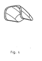
- the cover element DE which is used in the hearing aid according to FIG. 3, shown.
- the cover element DE is formed according to FIG. 4 as a shell, i. the outward facing surfaces remain unchanged, but the volume of porous material is reduced.
- the filter fineness is preferably selected between 10 to 40 microns, wherein the thickness of the shell is at least 0.5mm.
- FIG. 5 an embodiment of a hearing aid is shown in FIG. 5, in which two microphones M1 and M2 are used to change the directional characteristic.
- the two microphones M1 and M2 are arranged under the same cover element DE.
- the cover element DE is designed as a shell and delimits a space V, which has sound inlet openings SE1 and SE2, in whose vicinity one of the microphones M1 and M2 are respectively arranged.
- both microphones M1 and M2 are arranged under the same cover element DE, whereby also the volumes V in front of the microphones M1 and M2 are identical. Unavoidable contamination on the outwardly directed surface of the cover element DE have the same influence on both microphones M1 and M2.
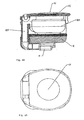
- FIG. 6 an in-the-ear (ITE) hearing aid is shown, wherein in Fig. 6A is a cross-section and in Fig. 6B is a plan view is shown.
- DE again denotes the cover element, with the aid of which a sound inlet opening SE is covered.
- a sound channel UEK can be seen, through which the sound waves are conducted to a microphone M.
- a battery BT and a housing E containing the electronics are also shown in FIG. 6A.
- the cover element DE can be seen, which in this embodiment is preferably designed as a ball sector.
- the IdO embodiment according to FIG. 6 differs above all by a different arrangement of the individual hearing device components. However, this does not deviate from the inventive principle.
- the above statements relate to hearing aids whose sound inlet openings are provided with a corresponding cover element.
- the sound outlet opening is additionally provided with a cover element.
- cover elements that are used to cover other vents.
- cover elements are excellent, wherein the cover element is preferably integrated flush with the surface in the hearing aid housing.
Landscapes
- Engineering & Computer Science (AREA)
- Physics & Mathematics (AREA)
- Signal Processing (AREA)
- General Health & Medical Sciences (AREA)
- Neurosurgery (AREA)
- Otolaryngology (AREA)
- Manufacturing & Machinery (AREA)
- Acoustics & Sound (AREA)
- Health & Medical Sciences (AREA)
- Details Of Audible-Bandwidth Transducers (AREA)
- Adornments (AREA)
- Finger-Pressure Massage (AREA)
- Headphones And Earphones (AREA)
- Soundproofing, Sound Blocking, And Sound Damping (AREA)
- Casings For Electric Apparatus (AREA)
Description
- Die vorliegende Erfindung betrifft ein Hörgerät nach dem Oberbegriff des Patentanspruchs 1.
- Hörgeräte weisen eine Schalleintrittsöffnung zum Aufnehmen von Umgebungslauten und eine Schallaustrittsöffnung zur Abgabe der im Hörgerät verarbeiteten Umgebungslaute auf. Dabei ist es von grösster Bedeutung, dass den Umgebungslauten in keiner Weise störende Geräusche überlagert werden, die in der Folge wie Umgebungslaute behandelt werden. Störende Geräusche können dabei die Ursache darin haben, dass Luftströmungen an Kanten am bzw. in der Nähe des Hörgerätes abreissen (Abriss-Problematik) oder dass Luftströmungen mit unterschiedlichen Geschwindigkeiten und/oder Richtungen im Bereich unmittelbar vor der Mikrophonmembran dazu führen, dass diese bewegt wird (Gradienten-Problematik). Diese beiden genannten Ursachen können auch in Kombination auftreten.
- In der US-4 073 366 ist ein Deckelement beschrieben, das über die Schalleintrittsöffnung eines Hörgerätes geklebt wird. Das bekannte Deckelement besteht aus mehreren Schichten, die an den Rändern zusammengeklebt sind und die aus porösen Materialien bestehen, womit verhindert werden soll, dass an den Kanten der Eintrittsöffnung infolge von abreissenden Luftströmungen störende Geräusche entstehen.
- In Patent Abstract of Japan, Vol. 97, No. 1 vom 31. Januar 1997 ist eine weitere Lehre offenbart, bei der in ähnlicher Weise wie bei der US 4 073 366 die Verwendung eines Deckelementes vorgeschlagen wird.
- Es hat sich gezeigt, dass mittels dieser bekannten Lehren die Störgeräusche insgesamt nur gering beeinflusst werden können, denn durch das Deckelement über der Eintrittsöffnung kann zwar die Störgeräuschbildung aufgrund der Gradienten-Problematik reduziert werden, nicht jedoch die Störgeräusche, die aufgrund der Abriss-Problematik entstehen. Der Grund dafür liegt darin, dass durch das Anbringen von Deckelementen über der Schalleintrittsöffnung zur Verminderung von Strömungsabrissen an deren Kanten neue potentielle Herde von Störgeräuschen an den Kanten des Deckelementes selbst entstehen. Damit ist die Quelle für Störgeräusche lediglich verschoben worden.
- Der Vollständigkeit halber wird auf die Druckschrift EP-0 310 866 verwiesen, in der offenbart wird, dass die Schallaustrittsöffnung zur Verhinderung des Eintritts von Ohrenschmalz (Cerumen) in das Hörgerät mit einem Deckelement abzudecken, wobei die Verwendung eines mikroporösen Materials vorgeschlagen wird. Darüber hinaus kann dieser Druckschrift entnommen werden, dass die Schalleintrittsöffnung dann mit einem Deckelement abgedeckt werden soll, sofern es sich um ein In-dem-Ohr-Hörgerät (IdO-Hörgerät) handelt, denn offensichtlich besteht nur dann eine Gefahr, dass Ohrenschmalz in das Hörgerät gelangt, wenn dieses im Ohr plaziert ist. Massnahmen zur Reduktion von störenden Geräuschen sind aus dieser Druckschrift nicht entnehmbar. Es handelt sich hier allein darum, die Verschmutzung von Hörgeräten zu vermeiden.
- Der vorliegenden Erfindung liegt daher die Aufgabe zugrunde, ein Hörgerät anzugeben, bei dem die Störgeräuschbildung vermindert ist.
- Diese Aufgabe wird durch die im kennzeichnenden Teil des Patentanspruchs 1 angegebenen Massnahmen gelöst. Vorteilhafte Ausgestaltungen der Erfindung sind in weiteren Ansprüchen angegeben.
- Die Erfindung weist folgende Vorteile auf: Durch die Integration mindestens eines Deckelementes in das Hörgerät selbst und die oberflächenbündige Anordnung des Deckelementes im Hörgerätgehäuse werden Kanten vermieden, die ansonsten Quelle von Störgeräuschen sind, womit der Abriss-Problematik Rechnung getragen ist. Gleichzeitig wird aber auch der Gradienten-Problematik Rechnung getragen, indem das Deckelement aus einem porösen, vorzugsweise aus einem offenporösen Material gefertigt ist und eine gewisse Dicke aufweist.
- Es hat sich gezeigt, dass sich als Material für die Deckelemente ein offenporöses Polyäthylen besonders eignet. Die Eigenschaften des Materials können dabei einerseits durch die Filterfeinheit, die der minimalen Teilchengrösse der gefilterten Teilchen entspricht, und anderseits durch die Offenporigkeit, die dem Verhältnis zwischen Porenöffnung und Restfläche entspricht, charakterisiert werden. Die Filterfeinheit wird auch etwa mit d50-Werten angegeben, wobei beim angegebenen d50-Wert 50% der Partikel den Filter passieren und 50% der Partikel zurückbehalten werden. Es hat sich herausgestellt, dass die d50-Werte für die Filterfeinheit zwischen 10µm und 200µm und die Offenporigkeit zwischen 70 und nahezu 100% liegen.
- Durch die Verwendung eines homogenen Materials für die Deckelemente wird eine hohe Reproduzierbarkeit derselben erreicht, da keine Materialübergänge vorgesehen sind, welche die akustischen Eigenschaften des Gesamtsystems nachhaltig beeinflussen können, denn Materialübergänge beinhalten das Risiko, dass Abweichungen vom akustischen Normverhalten entstehen. Ferner ist sowohl die Fertigung als auch die Montage der erfindungsgemässen Deckelemente in Hörgeräten wesentlich einfacher und damit auch kostengünstiger.
- Auf der anderen Seite besteht eine Ausführungsvariante der Erfindung darin, dass die aus einem homogenen Material gefertigten Deckelemente mit einer dünnen durchlässigen Schicht, beispielsweise Teflon, überzogen sind. Dies ergibt eine höhere Beständigkeit, was insbesondere bei äusseren chemischen Einflüssen von grosser Bedeutung ist. Darüber hinaus wird aber der Abriss-Problematik weiter Rechnung getragen, denn durch das Beschichten erhält das Deckelement eine feinere Oberfläche. Damit werden Abriss-Störgeräusche, die aufgrund von Unebenheiten in der Oberfläche der Deckelemente erzeugt werden, weiter vermindert.
- Die Erfindung wird nachfolgend anhand von Zeichnungen beispielsweise näher erläutert. Dabei zeigen
- Fig. 1
- einen Längsschnitt durch Teile eines Hörgerätes mit eingesetztem Deckelement,
- Fig. 2
- das Deckelement gemäss Fig. 1 in perspektivischer Darstellung,
- Fig. 3
- eine Seitenansicht einer weiteren Ausführungsform eines erfindungsgemässen Hörgerätes mit eingesetztem Deckelement,
- Fig. 4
- das Deckelement gemäss Fig. 3 in perspektivischer Darstellung,
- Fig. 5
- einen Längsschnitt durch eine weitere Ausführungsform eines erfindungsgemässen Hörgerätes mit mehreren Mikrophonen und
- Fig. 6A und 6B
- einen Schnitt durch bzw. eine Draufsicht auf ein In-dem-Ohr-Hörgerät mit einem erfindungsgemässen Deckelement.
- Fig. 1 zeigt einen Längsschnitt durch ein Hörgerät bestehend aus einem Verstärkungselement VE und einem Hakenelement HE. Das Hakenelement HE ist dabei lösbar mit dem Verstärkungselement VE verbunden, d.h. das Hakenelement HE bzw. das Verstärkungselement VE können beliebig ausgetauscht bzw. ersetzt werden.
- Im Verstärkungselement VE wird im wesentlichen die elektronische Bearbeitung der akustischen Signale (siehe Pfeil ES) vorgenommen, die - nach der Verarbeitung - an das Hakenelement HE (siehe Pfeil SS) bzw. in einen darin enthaltenen Schallübertragungskanal UEK übergeben werden. Auf das Verstärkungselement VE des Hörgerätes ist an dieser Stelle nicht weiter einzugehen, da die Erfindung insbesondere auf die Ausstattung des Hakenelementes HE gerichtet ist.
- Es wird jedoch ausdrücklich darauf hingewiesen, dass die Erfindung nicht auf Hörgeräte beschränkt ist, die aus zwei Teilen, nämlich Verstärkungselement VE und Hakenelement HE, bestehen. Vielmehr eignet sich die Erfindung insbesondere auch für Hörgeräte, die nur aus einem Gehäuseteil bestehen. Darüber hinaus kann die Erfindung sowohl bei IdO-(In-dem-Ohr)-Hörgeräten als auch bei HdO-(Hinter-dem-Ohr)-Hörgeräten angewendet werden.
- Im Hinblick auf die vorliegende Erfindung ist die äussere Form des Verstärkungselementes VE von Bedeutung: Insbesondere im Übergangsbereich zwischen Verstärkungselement VE und Hakenelement HE - wiederum in bezug auf die Ausführungsform gemäss Fig. 1 - weisen diese identische - zumindest jedoch ähnliche - Konturen und Oberflächenbeschaffenheiten auf. Insgesamt weist das ganze Hörgerät keine scharfen Kanten auf, damit keine störenden Geräusche erzeugt werden.
- Das Hakenelement HE enthält vorzugsweise keine elektronischen Komponenten, sondern ist insbesondere dazu da, Umgebungslaute möglichst störungsfrei aufzunehmen und - in Richtung Pfeil ES - in die Verstärkungseinheit VE zu übertragen. Anderseits werden die verarbeiteten akustischen Signale - in Richtung Pfeil SS - durch den Schallübertragungskanal UEK im Hakenelement HE zu einer Schallaustrittsöffnung SA übertragen, wo die akustischen Signale in den eigentlichen Gehörgang des Hörgeräteträgers gelangen.
- Im Hakenelement HE ist ein Deckelement DE vorgesehen, der den Bereich der Schalleintrittsöffnung SE gegenüber der Aussenumgebung abdeckt, wobei das Deckelement DE in das Hakenelement HE derart integriert ist, dass keine Kanten an den Übergangsstellen zwischen dem Hakenelement HE und dem Deckelement DE vorhanden sind, d.h. das Deckelement DE ist oberflächenbündig in das Hakenelement HE integriert. Darüber hinaus ist das Deckelement DE gegen Aussen kugelförmig, zumindest aber kugelsektorförmig ausgebildet. Damit sind von Seiten Hörgerät keine Kanten vorhanden, die Quellen von Störgeräuschen sein können.
- Wie erwähnt weisen die für die Deckelemente DE verwendeten Materialien eine gewisse Porosität, vorzugsweise eine gewisse Offenporosität auf, die durch die beiden Parameter Filterfeinheit und Offenporigkeit definiert werden kann. Im übrigen weist das verwendete Material gemäss einer erfindungsgemässen Ausführungsform eine homogene Struktur auf.
- Es hat sich gezeigt, dass, wenn das verwendete Material eine zwischen 10µm und 200µm (Angaben in d50-Werten) liegende Filterfeinheit und eine zwischen 70% und nahezu 100% liegende Offenporigkeit aufweist, besonders gute Ergebnisse erzielt werden können. Allerdings hängt die Wahl dieser Parameter, insbesondere die Filterfeinheit, erheblich von der Dicke des Deckelementes bzw. von dessen Volumen ab. So hat sich herausgestellt, dass zur Reduktion des Gradienten-Effektes ein möglichst grosses Volumen für das Deckelement von Vorteil ist. Allerdings bewirkt eine Vergrösserung des Volumens gleichzeitig eine ungewollte Veränderung der akustischen Impedanz. Damit muss ein Kompromiss zwischen diesen beiden Optimierungsbedingungen gefunden werden, was anhand Fig. 2 weiter erläutert wird.
- Die folgenden Materialien eignen sich besonders im Zusammenhang mit dieser Erfindung: gesintertes Polymer, Polyäthylen, Schaumkeramik (auch etwa als keramischer Schaum bezeichnet), geschäumtes Polyurethan, gesintertes Glas oder gesintertes Metall.
- Es wurde bereits darauf hingewiesen, dass das Deckelement aus einem homogenen Material gefertigt ist. In einer weiteren Ausführungsform der Erfindung wird vorgeschlagen, die Aussenseite des Deckelementes mit einer dünnen, feinporigen Schicht zu überziehen. Diese Schicht besteht vorzugsweise aus Teflon. Die Vorteile einer solchen Schicht bestehen darin, dass die chemische Beständigkeit erhöht ist, was den Einsatz der erfindungsgemässen Hörgeräte bei starken äusseren Einflüssen ermöglicht. Während beim normalen alltäglichen Einsatz ein Abstossen von Wasser, Körperschweiss und Körperfett notwendig und gefordert ist, ist in speziell gelagerten Fällen auch ein Abstossen von anderen chemischen Substanzen denkbar und auch wünschenswert.
- Von grösster Bedeutung für den täglichen Einsatz von Hörgeräten ist deren Wetterbeständigkeit, die dadurch erreicht wird, dass ein hydrophobes Material für das Deckelement zum Einsatz kommt oder dass zumindest die Oberfläche mit einem hydrophoben Material behandelt bzw. beschichtet ist.
- Fig. 2 zeigt, in perspektivischer Darstellung, das Deckelement DE für das Hörgerät gemäss Fig. 1. Ersichtlich sind eine nach Aussen gerichtete Fläche AF und nach Innen gerichtete Flächen IF. Die Unterteilung der Fläche AF in drei Teilflächen ist lediglich für eine deutliche Darstellung der Oberflächenkrümmungen vorgenommen worden und hat ansonsten keine Bedeutung. Das gleiche trifft zu für die vier Teilflächen der nach Innen gerichteten Fläche IF.
- Das in Fig. 2 dargestellte Deckelement DE weist aufgrund der Grossvolumigkeit ein gutes Verhalten in bezug auf den Gradienten-Effekt auf. Allerdings bestehen aufgrund dieser Grossvolumigkeit Einschränkungen in bezug auf die akustische Impedanz und in bezug auf die Körperschalleigenschaften des Hörgerätes. Dem kann dadurch entgegengesteuert werden, indem die Feinporigkeit vorzugsweise bei 80 bis 100µm (d50-Werte) gewählt wird.
- Fig. 3 zeigt ein erfindungsgemässes Hörgerät im Längsschnitt, wobei für die einzelnen Teile die gleichen Bezugszeichen verwendet wurden, wie sie bereits beim Hörgerät gemäss Fig. 1 eingesetzt wurden.
- Wie aus Fig. 3 ersichtlich ist, ist das Deckelement DE bei dieser Ausführungsform im Randbereich abgerundet. Entsprechend ist die Ausnehmung im Hakenelement HE zur Aufnahme des Deckelementes DE der äusseren Form desselben angepasst worden. Diese Ausführungsform der Erfindung hat den zusätzlichen Vorteil, dass eine kompaktere und somit stabilere Bauweise erreicht wird als bei einem Hörgerät gemäss Fig. 1. Das Deckelement DE wird nämlich nunmehr vom Hakenelement HE derart umfasst, dass die Bewegungsfreiheit des Deckelementes DE in radialer Richtung eingeschränkt wird. Für die Montage und Demontage kann das Deckelement DE senkrecht zur Schnittebene gemäss Fig. 3 bewegt werden.
- In Fig. 4 ist das Deckelement DE, das in das Hörgerät gemäss Fig. 3 einsetzbar ist, dargestellt. Neben den bereits anhand Fig. 3 erläuterten Unterschieden gegenüber dem Hörgerät gemäss Fig. 1 bzw. 2 ist das Deckelement DE gemäss Fig. 4 als Schale ausgebildet, d.h. die nach aussen gerichteten Flächen bleiben unverändert, jedoch das Volumen aus porösem Material wird reduziert. Bei einer solchen Schalenform wird die Filterfeinheit vorzugsweise zwischen 10 bis 40µm gewählt, wobei die Dicke der Schale dabei mindestens 0,5mm beträgt.
- Schliesslich ist in Fig. 5 eine Ausführungsform eines Hörgerätes dargestellt, bei der zwei Mikrophone M1 und M2 zur Veränderung der Richtcharakteristik zum Einsatz kommen. Erfindungsgemäss werden hierbei die beiden Mikrophone M1 und M2 unter dem selben Deckelement DE angeordnet. Das Deckelement DE ist als Schale ausgebildet und begrenzt einen Raum V, der Schalleintrittsöffnungen SE1 und SE2 aufweist, in deren Umgebung je eines der Mikrophone M1 und M2 angeordnet sind.
- Bekanntlich ist es bei der Verwendung von mehreren Mikrophonen zur Veränderung der Richtcharakteristik von grösster Bedeutung, dass die Charakteristiken der Mikrophone identisch sind. Dies wird im höchsten Masse dadurch erreicht, dass beide Mikrophone M1 und M2 unter dem selben Deckelement DE angeordnet sind, womit auch die Volumen V vor den Mikrophonen M1 und M2 identisch sind. Unvermeidbare Verschmutzungen auf der nach aussen gerichteten Oberfläche des Deckelementes DE haben gleiche Einflüsse auf beide Mikrophone M1 und M2.
- In Fig. 6 ist ein In-dem-Ohr-(IdO)-Hörgerät dargestellt, wobei in Fig. 6A ein Querschnitt und in Fig. 6B eine Draufsicht dargestellt ist. In Fig. 6A ist mit DE wiederum das Deckelement bezeichnet, mit Hilfe dessen eine Schalleintrittsöffnung SE abgedeckt ist. Des weiteren ist ein Schallkanal UEK ersichtlich, durch den die Schallwellen zu einem Mikrophon M geleitet werden. Der Vollständigkeit halber ist in Fig. 6A auch eine Batterie BT und ein die Elektronik enthaltendes Gehäuse E eingezeichnet.
- In der Draufsicht gemäss Fig. 6B ist das Deckelement DE erkennbar, das in dieser Ausführungsform vorzugsweise als Kugelsektor ausgebildet ist.
- Gegenüber den Hörgeräten gemäss Fig. 1 bis 5 unterscheidet sich die IdO-Ausführungsform gemäss Fig. 6 vor allem durch eine andere Anordnung der einzelnen Hörgerätkomponenten. Dadurch wird jedoch vom erfindungsgemässen Prinzip nicht abgewichen.
- Die vorstehenden Ausführungen beziehen sich auf Hörgeräte, deren Schalleintrittsöffnungen mit einem entsprechenden Deckelement versehen sind. Gemäss einer Weiterbildung der Erfindung wird zusätzlich die Schallaustrittsöffnung mit einem Deckelement versehen. Damit wird ein Hörgerät geschaffen, das nicht nur in bezug auf das akustische Verhalten optimal ist, sondere insbesondere auch gegen jegliche äussere Einflüsse gewappnet ist.
- Denkbar in diesem Zusammenhang sind auch Deckelemente, die zum Abdecken von anderen Lüftungsöffnungen verwendet werden. So ist beispielsweise beim Einsatz von Zink-Luft Batterien zu beachten, dass der Luftzutritt gewährleistet ist. Auch hier eignen sich die vorstehend erläuterten Deckelemente vorzüglich, wobei das Deckelement vorzugsweise oberflächenbündig in das Hörgerätgehäuse integriert ist.
Claims (13)
- Hörgerät mit einer Schalleintrittsöffnung (SE) und einer Schallaustrittsöffnung (SA), wobei ein Schall-durchlässiges als Schale ausgebildete Deckelement (DE) zur Abdeckung der Schalleintrittsöffnung (SE) vorgesehen ist, das zur Vermeidung von Störgeräuschen oberflächenbündig in das Hörgerätgehäuse integriert ist und eine Dicke von mindestens 0.5 mm, eine Filterfeinheit von 10 µm bis 200 µm und eine Offenporigkeit von 70 bis nahezu 100% aufweist.
- Hörgerät nach Anspruch 1, dadurch gekennzeichnet, dass ein weiteres Deckelement vorgesehen ist, das die Schallaustrittsöffnung (SA) abdeckt, wobei das weitere Deckelement oberflächenbündig in das Hörgerätgehäuse integriert ist.
- Hörgerät nach Anspruch 1 oder 2, dadurch gekennzeichnet, dass mindestens ein Deckelement (DE) aus gesintertem Polymer, Schaumkeramik, gesintertem Glas oder gesintertem Metall besteht.
- Hörgerät nach einem der vorangehenden Ansprüche, dadurch gekennzeichnet, dass die Deckelemente (DE) aus einem hydrophoben und/oder oliophoben Material bestehen.
- Hörgerät nach einem der Ansprüche 2 bis 4, dadurch gekennzeichnet, dass das weitere Deckelement eine Filterfeinheit von 10µm bis 200µm und eine Offenporigkeit von 70 bis nahezu 100% aufweist.
- Hörgerät nach einem der vorangehenden Ansprüche, dadurch gekennzeichnet, dass mindestens ein Deckelement (DE) gegen aussen mit einer Schicht, vorzugsweise aus Teflon, überzogen ist.
- Hörgerät nach einem der vorangehenden Ansprüche, dadurch gekennzeichnet, dass die Struktur mindestens eines Deckelementes (DE) homogen ist.
- Hörgerät nach einem der vorangehenden Ansprüche, dadurch gekennzeichnet, dass das Deckelement (DE) aus einem Material hergestellt ist, das vorzugsweise eine Filterfeinheit zwischen 10 und 40µm aufweist.
- Hörgerät nach einem der vorangehenden Ansprüche, dadurch gekennzeichnet, dass die Schalleintrittsöffnung (SE) und das Deckelement (DE) in einem Hakenelement (HE) enthalten sind, das mit einem Verstärkungselement (VE) lösbar gekoppelt ist.
- Hörgerät nach einem der Ansprüche 1 bis 8, dadurch gekennzeichnet, dass die Schallaustrittsöffnung (SA) und das Deckelement (DE) in einem Hakenelement (HE) enthalten sind, das mit einem Verstärkungselement (VE) lösbar gekoppelt ist.
- Hörgerät nach einem der vorangehenden Ansprüche, dadurch gekennzeichnet, dass mindestens eines der Deckelemente (DE) lösbar mit dem Hörgerätgehäuse gekoppelt ist.
- Hörgerät nach einem der vorangehenden Ansprüche, dadurch gekennzeichnet, dass unter dem Deckelement (DE) zur Abdeckung der Schalleintrittsöffnung (SE) mindestens zwei Mikrophone (M1, M2) angeordnet sind.
- Hörgerät nach einem der vorangehenden Ansprüche, dadurch gekennzeichnet, dass das Hörgerätgehäuse eine Lüftungsöffnung aufweist, die den Luftzutritt zu einer Zink-Luft Batterie gewährleistet, wobei die Luftzutrittsöffnung mit einem weiteren Deckelement abgedeckt ist, das oberflächenbündig in das Hörgerätgehäuse integriert ist.
Priority Applications (1)
| Application Number | Priority Date | Filing Date | Title |
|---|---|---|---|
| EP99904679A EP1060640B2 (de) | 1998-03-02 | 1999-03-01 | Hörgerät |
Applications Claiming Priority (4)
| Application Number | Priority Date | Filing Date | Title |
|---|---|---|---|
| EP98103587A EP0847227B1 (de) | 1998-03-02 | 1998-03-02 | Hörgerät |
| EP98103587 | 1998-03-02 | ||
| EP99904679A EP1060640B2 (de) | 1998-03-02 | 1999-03-01 | Hörgerät |
| PCT/CH1999/000093 WO1999045744A1 (de) | 1998-03-02 | 1999-03-01 | Hörgerät |
Publications (3)
| Publication Number | Publication Date |
|---|---|
| EP1060640A1 EP1060640A1 (de) | 2000-12-20 |
| EP1060640B1 EP1060640B1 (de) | 2003-01-22 |
| EP1060640B2 true EP1060640B2 (de) | 2007-03-14 |
Family
ID=8231507
Family Applications (2)
| Application Number | Title | Priority Date | Filing Date |
|---|---|---|---|
| EP98103587A Revoked EP0847227B1 (de) | 1998-03-02 | 1998-03-02 | Hörgerät |
| EP99904679A Expired - Lifetime EP1060640B2 (de) | 1998-03-02 | 1999-03-01 | Hörgerät |
Family Applications Before (1)
| Application Number | Title | Priority Date | Filing Date |
|---|---|---|---|
| EP98103587A Revoked EP0847227B1 (de) | 1998-03-02 | 1998-03-02 | Hörgerät |
Country Status (8)
| Country | Link |
|---|---|
| US (2) | US6574343B1 (de) |
| EP (2) | EP0847227B1 (de) |
| JP (1) | JP4608095B2 (de) |
| AT (1) | ATE231678T1 (de) |
| AU (1) | AU2508999A (de) |
| DE (2) | DE59809366D1 (de) |
| DK (2) | DK0847227T3 (de) |
| WO (1) | WO1999045744A1 (de) |
Cited By (1)
| Publication number | Priority date | Publication date | Assignee | Title |
|---|---|---|---|---|
| US8873783B2 (en) | 2010-03-19 | 2014-10-28 | Advanced Bionics Ag | Waterproof acoustic element enclosures and apparatus including the same |
Families Citing this family (60)
| Publication number | Priority date | Publication date | Assignee | Title |
|---|---|---|---|---|
| DE59809366D1 (de) * | 1998-03-02 | 2003-10-02 | Phonak Ag Staefa | Hörgerät |
| WO2000045617A2 (de) * | 1999-01-27 | 2000-08-03 | Auric Hörsysteme Gmbh & Co. Kg | Hör-behandlungsgerät |
| NL1011778C1 (nl) | 1999-04-13 | 2000-10-16 | Microtronic Nederland Bv | Microfoon voor een hoorapparaat en een hoorapparaat voorzien van een dergelijke microfoon. |
| WO2000079835A1 (de) | 1999-06-16 | 2000-12-28 | Phonak Ag | Hinterohr-hörgerät |
| WO2000022878A2 (de) * | 2000-02-09 | 2000-04-20 | Phonak Ag | Hörgerät |
| US6741716B2 (en) | 2002-02-19 | 2004-05-25 | Starkey Laboratories, Inc. | Affixed behind-the-ear child resistant volume control cover |
| DE10260303B3 (de) * | 2002-12-20 | 2004-06-17 | Siemens Audiologische Technik Gmbh | Mikrofonmudul für ein Hörhilfegerät |
| DE10260307B4 (de) * | 2002-12-20 | 2007-02-22 | Siemens Audiologische Technik Gmbh | Elektroakustischer Miniaturwandler für ein Hörhilfegerät |
| US20040196996A1 (en) * | 2003-04-02 | 2004-10-07 | Feitel Mark A. | Hearing aid and hearing aid accessory cosmetic and functional cover |
| USD516216S1 (en) * | 2003-11-21 | 2006-02-28 | Phonak Holding Ag | Hearing aid |
| EP1432285B1 (de) * | 2003-12-30 | 2016-06-08 | Sonova AG | Hydrophobe Beschichtung einzelner Komponenten von Hörgeräten |
| US20050249369A1 (en) * | 2004-05-05 | 2005-11-10 | Phonak Ag | Flexible frequency response shaping |
| US7873058B2 (en) * | 2004-11-08 | 2011-01-18 | Mosaid Technologies Incorporated | Outlet with analog signal adapter, a method for use thereof and a network using said outlet |
| DE102004062279A1 (de) * | 2004-12-23 | 2006-05-11 | Siemens Audiologische Technik Gmbh | Zerumenschutzeinrichtung für ein Hörhilfegerät |
| DE102005012149B3 (de) * | 2005-03-16 | 2006-09-21 | Siemens Audiologische Technik Gmbh | Abdeckvorrichtung für mindestens einen Mikrofoneingang eines Hörgeräts und Hörgerät mit einer Abdeckvorrichtung |
| US7991174B2 (en) * | 2005-06-30 | 2011-08-02 | Insound Medical, Inc. | Hearing aid battery barrier |
| DK1578168T3 (da) | 2005-07-01 | 2011-04-11 | Phonak Ag | Indretning til anbringelse i øret |
| US7804975B2 (en) | 2005-07-01 | 2010-09-28 | Phonak Ag | In-ear device |
| US20070127757A2 (en) * | 2005-07-18 | 2007-06-07 | Soundquest, Inc. | Behind-The-Ear-Auditory Device |
| WO2007011846A2 (en) * | 2005-07-18 | 2007-01-25 | Soundquest, Inc. | In-ear auditory device and methods of using same |
| DK1763280T3 (en) * | 2005-09-08 | 2017-08-07 | Oticon As | Audio device comprising a microphone |
| US7756284B2 (en) * | 2006-01-30 | 2010-07-13 | Songbird Hearing, Inc. | Hearing aid circuit with integrated switch and battery |
| US7756285B2 (en) * | 2006-01-30 | 2010-07-13 | Songbird Hearing, Inc. | Hearing aid with tuned microphone cavity |
| USD557255S1 (en) * | 2006-02-23 | 2007-12-11 | Sony Ericsson Mobile Communications Ab | Headset |
| DE102006026785A1 (de) * | 2006-06-07 | 2007-12-13 | Siemens Audiologische Technik Gmbh | Abdeckvorrichtung für Hörgerät-Gehäuseanordnung |
| US7889880B1 (en) * | 2006-08-08 | 2011-02-15 | Robert George Coffey | Hearing aid wind-vortex noise preventer blanket accessories |
| US8846161B2 (en) * | 2006-10-03 | 2014-09-30 | Brigham Young University | Hydrophobic coating and method |
| WO2008042986A2 (en) * | 2006-10-03 | 2008-04-10 | Sonic Innovations, Inc. | Hydrophobic and oleophobic coating and method for preparing the same |
| DE102007010602A1 (de) * | 2007-03-05 | 2008-09-11 | Siemens Audiologische Technik Gmbh | Spannungsquelle mit einem beschichteten Gehäuse |
| WO2008154954A1 (en) | 2007-06-18 | 2008-12-24 | Phonak Ag | Cover for apertures of an electric micro-device housing |
| USD584719S1 (en) * | 2007-06-22 | 2009-01-13 | Sennheiser Communications A/S | Wireless headset |
| DE102007034230A1 (de) * | 2007-07-23 | 2009-01-29 | Siemens Medical Instruments Pte. Ltd. | Hörvorrichtung mit Mikrofonabdeckung |
| KR200448686Y1 (ko) * | 2008-02-04 | 2010-05-07 | (주)머티리얼솔루션테크놀로지 | 보청기 |
| US20120163642A1 (en) * | 2009-09-07 | 2012-06-28 | Phonak Ag | Advanced microphone protection |
| US8792665B2 (en) * | 2009-12-31 | 2014-07-29 | Starkey Laboratories, Inc. | Foreign material mitigation for hearing assistance device components |
| US9369816B2 (en) | 2009-12-31 | 2016-06-14 | Starkey Laboratories, Inc. | Omniphobic perforated barrier for hearing aid transducers |
| EP2534855B1 (de) * | 2010-02-11 | 2018-01-24 | Sivantos Pte. Ltd. | Hinter-dem-ohr-hörgerät mit steckverbinder |
| US9161131B2 (en) * | 2010-03-25 | 2015-10-13 | K&E Holdings, LLC | Stereo audio headphone apparatus for a user having a hearing loss and related methods |
| DE102010043413A1 (de) * | 2010-11-04 | 2012-05-10 | Siemens Medical Instruments Pte. Ltd. | Verfahren und Hörgerät zur Ermittlung von Nässe |
| EP2666306B1 (de) * | 2011-01-18 | 2017-03-15 | Advanced Bionics AG | Feuchtigkeitsbeständige kopfstücke und implantierbare cochlear-stimulationssysteme damit |
| CN103370948B (zh) | 2011-02-07 | 2016-02-17 | 京瓷株式会社 | 装饰品用构件及具备该装饰品用构件的装饰品 |
| US9071918B2 (en) | 2011-03-18 | 2015-06-30 | Starkey Laboratories, Inc. | Ball and socket connection with an acoustic seal and mounting interface for a hearing assistance device |
| US9386384B2 (en) * | 2012-01-03 | 2016-07-05 | Starkey Laboratories, Inc. | Hearing instrument transduction apparatus using ferroelectret polymer foam |
| USD712881S1 (en) * | 2013-05-24 | 2014-09-09 | Qualcomm Incorporated | Earpiece |
| US10284974B2 (en) | 2013-07-10 | 2019-05-07 | Starkey Laboratories, Inc. | Acoustically transparent barrier layer to seal audio transducers |
| JP2015073167A (ja) | 2013-10-02 | 2015-04-16 | 日東電工株式会社 | 補聴器及び補聴器充電システム |
| JP6604708B2 (ja) | 2013-10-02 | 2019-11-13 | 日東電工株式会社 | 補聴器 |
| USD838688S1 (en) * | 2017-05-07 | 2019-01-22 | Xiaoliang Liu | Wireless headset |
| USD825764S1 (en) * | 2017-07-03 | 2018-08-14 | Enrique Gajstut | Sound amplifier |
| DE102017219470A1 (de) * | 2017-11-02 | 2019-05-02 | Sivantos Pte. Ltd. | Hörgerät |
| USD861634S1 (en) * | 2017-12-18 | 2019-10-01 | Wen-Tse HUANG | Bluetooth headset |
| USD903634S1 (en) * | 2019-04-29 | 2020-12-01 | Shenzhen Quanmeng Technology Co., Ltd. | Wireless headset |
| USD945401S1 (en) * | 2019-12-23 | 2022-03-08 | Bose Corporation | Audio headset |
| USD939476S1 (en) * | 2019-12-23 | 2021-12-28 | Bose Corporation | Audio headset |
| USD903635S1 (en) * | 2020-07-09 | 2020-12-01 | Shenzhen Link Dream Electronics Co., Ltd | Earphone |
| US11638107B2 (en) | 2020-11-11 | 2023-04-25 | Gn Hearing A/S | Hearing device with two microphone filters |
| USD944228S1 (en) * | 2021-03-16 | 2022-02-22 | Shenzhen Quanmeng Technology Co., Ltd. | Earphone |
| USD947812S1 (en) * | 2021-04-26 | 2022-04-05 | Shenzhenshi Annso Technology Co., Ltd | Wireless earphone |
| USD1025953S1 (en) * | 2022-06-08 | 2024-05-07 | Yealink (Xiamen) Network Technology Co., Ltd. | Audio headset |
| USD1051093S1 (en) * | 2023-01-16 | 2024-11-12 | Shenzhen Fushike Electronic Co., Ltd | Wireless earphone |
Citations (4)
| Publication number | Priority date | Publication date | Assignee | Title |
|---|---|---|---|---|
| US3976848A (en) † | 1975-08-21 | 1976-08-24 | Estes Roger Q | Disposable noise reducing hearing aid attachment |
| US4073366A (en) † | 1976-07-26 | 1978-02-14 | Estes Roger Q | Disposable noise reducing hearing aid attachment |
| EP0629101A1 (de) † | 1993-06-11 | 1994-12-14 | Ascom Audiosys Ag | Im Ohr zu tragende Hörhilfe und Verfahren zu deren Herstellung |
| WO1997045829A1 (en) † | 1996-05-31 | 1997-12-04 | W.L. Gore & Associates, Inc. | Protective cover assembly having sound transmission characteristics |
Family Cites Families (29)
| Publication number | Priority date | Publication date | Assignee | Title |
|---|---|---|---|---|
| DE1153797B (de) | 1961-12-02 | 1963-09-05 | Robert Bosch Elektronik Ges Mi | Hinter dem Ohr zu tragendes Schwerhoerigengeraet |
| US3265153A (en) * | 1962-06-27 | 1966-08-09 | Electro Voice | Acoustical device with protective screen |
| AT265384B (de) | 1966-06-17 | 1968-10-10 | Akg Akustische Kino Geraete | Schallempfänger mit einem oder mehreren Einzelmikrophonen |
| US3770911A (en) | 1972-07-21 | 1973-11-06 | Industrial Research Prod Inc | Hearing aid system |
| NL7306005A (de) * | 1973-05-01 | 1974-11-05 | ||
| CA1029668A (en) * | 1975-06-23 | 1978-04-18 | Unitron Industries Limited | Hearing aid having adjustable directivity |
| US4122015A (en) * | 1977-06-06 | 1978-10-24 | Nippon Seisen Co., Ltd. | Fortified metal filter and its preparative procedure |
| US4600077A (en) * | 1985-01-25 | 1986-07-15 | Drever Leslie C | Microphone wind shroud |
| DE8713369U1 (de) * | 1987-10-05 | 1989-02-09 | Siemens AG, 1000 Berlin und 8000 München | Vorrichtung zum Verschließen von Öffnungen an Hörgeräten oder Ohrpaßstücken für Hörgeräte |
| NL8802516A (nl) * | 1988-10-13 | 1990-05-01 | Philips Nv | Hoorapparaat met rondzing onderdrukking. |
| DE3928680A1 (de) | 1989-08-30 | 1991-03-07 | Systec Rationalisierungstechni | Einlege- und entnahmevorrichtung fuer eine weiterverarbeitende maschine |
| CA2014960C (en) * | 1990-04-19 | 1995-07-25 | Horst Arndt | Modular hearing aid |
| AT407815B (de) | 1990-07-13 | 2001-06-25 | Viennatone Gmbh | Hörgerät |
| JPH089891Y2 (ja) * | 1990-11-27 | 1996-03-21 | リオン株式会社 | 補聴器の電池収納装置 |
| CH681411A5 (de) * | 1991-02-20 | 1993-03-15 | Phonak Ag | |
| US5133016A (en) * | 1991-03-15 | 1992-07-21 | Wallace Clark | Hearing aid with replaceable drying agent |
| US5249234A (en) * | 1991-10-11 | 1993-09-28 | Butler Michael J | Cover for behind-the-ear type hearing aids and methods of making and using the same |
| DE4205376C1 (en) * | 1992-02-21 | 1993-09-16 | Siemens Audiologische Technik Gmbh, 91058 Erlangen, De | Housing for hearing aid worn on head - has visible section of transparent material and inside section of opaque material |
| CH683263A5 (de) | 1992-02-25 | 1994-02-15 | Weidmann H Ag | Offenporiger dimensionsstabiler Körper. |
| US5524056A (en) * | 1993-04-13 | 1996-06-04 | Etymotic Research, Inc. | Hearing aid having plural microphones and a microphone switching system |
| JP2837638B2 (ja) * | 1995-03-07 | 1998-12-16 | リオン株式会社 | 耳掛け式補聴器 |
| DE19603806A1 (de) | 1996-02-02 | 1997-08-07 | Resound Gmbh | Bausatz für modulare elektrische Im-Ohr-Hörgeräte |
| US5724431A (en) * | 1996-02-26 | 1998-03-03 | Siemens Hearing Instruments, Inc. | Zinc-air dry cell holder and hearing aid that uses it |
| DE19635229C2 (de) | 1996-08-30 | 2001-04-26 | Siemens Audiologische Technik | Richtungsempfindliche Hörhilfe |
| DE19636800A1 (de) * | 1996-09-11 | 1998-03-12 | Audio Service Gmbh As | Im-Ohr-Hörgerät |
| DE29623264U1 (de) * | 1996-10-11 | 1998-02-05 | Otto Bock Orthopädische Industrie Besitz- und Verwaltungs-Kommanditgesellschaft, 37115 Duderstadt | Erwärmvorrichtung für Kunststoffplatten |
| DE19706306C1 (de) * | 1997-02-18 | 1998-10-08 | Siemens Audiologische Technik | Im Ohr tragbares Hörhilfegerät |
| DE59809366D1 (de) * | 1998-03-02 | 2003-10-02 | Phonak Ag Staefa | Hörgerät |
| DE19810043A1 (de) * | 1998-03-09 | 1999-09-23 | Siemens Audiologische Technik | Hörgerät mit einem Richtmikrofon-System |
-
1998
- 1998-03-02 DE DE59809366T patent/DE59809366D1/de not_active Revoked
- 1998-03-02 EP EP98103587A patent/EP0847227B1/de not_active Revoked
- 1998-03-02 DK DK98103587T patent/DK0847227T3/da active
-
1999
- 1999-03-01 AU AU25089/99A patent/AU2508999A/en not_active Abandoned
- 1999-03-01 EP EP99904679A patent/EP1060640B2/de not_active Expired - Lifetime
- 1999-03-01 WO PCT/CH1999/000093 patent/WO1999045744A1/de not_active Ceased
- 1999-03-01 AT AT99904679T patent/ATE231678T1/de not_active IP Right Cessation
- 1999-03-01 DK DK99904679T patent/DK1060640T4/da active
- 1999-03-01 JP JP2000535179A patent/JP4608095B2/ja not_active Expired - Fee Related
- 1999-03-01 DE DE59904091T patent/DE59904091D1/de not_active Expired - Lifetime
-
2000
- 2000-09-01 US US09/654,337 patent/US6574343B1/en not_active Expired - Fee Related
-
2003
- 2003-02-28 US US10/376,834 patent/US7372973B2/en not_active Expired - Fee Related
Patent Citations (4)
| Publication number | Priority date | Publication date | Assignee | Title |
|---|---|---|---|---|
| US3976848A (en) † | 1975-08-21 | 1976-08-24 | Estes Roger Q | Disposable noise reducing hearing aid attachment |
| US4073366A (en) † | 1976-07-26 | 1978-02-14 | Estes Roger Q | Disposable noise reducing hearing aid attachment |
| EP0629101A1 (de) † | 1993-06-11 | 1994-12-14 | Ascom Audiosys Ag | Im Ohr zu tragende Hörhilfe und Verfahren zu deren Herstellung |
| WO1997045829A1 (en) † | 1996-05-31 | 1997-12-04 | W.L. Gore & Associates, Inc. | Protective cover assembly having sound transmission characteristics |
Cited By (2)
| Publication number | Priority date | Publication date | Assignee | Title |
|---|---|---|---|---|
| US8873783B2 (en) | 2010-03-19 | 2014-10-28 | Advanced Bionics Ag | Waterproof acoustic element enclosures and apparatus including the same |
| US9204229B2 (en) | 2010-03-19 | 2015-12-01 | Advanced Bionics Ag | Waterproof acoustic element enclosures and apparatus including the same |
Also Published As
| Publication number | Publication date |
|---|---|
| DE59904091D1 (de) | 2003-02-27 |
| DE59809366D1 (de) | 2003-10-02 |
| JP4608095B2 (ja) | 2011-01-05 |
| ATE231678T1 (de) | 2003-02-15 |
| DK0847227T3 (da) | 2003-12-22 |
| EP0847227A3 (de) | 1998-10-21 |
| US6574343B1 (en) | 2003-06-03 |
| JP2002506335A (ja) | 2002-02-26 |
| EP0847227A2 (de) | 1998-06-10 |
| DK1060640T3 (da) | 2003-04-22 |
| AU2508999A (en) | 1999-09-20 |
| US7372973B2 (en) | 2008-05-13 |
| EP1060640B1 (de) | 2003-01-22 |
| US20030142843A1 (en) | 2003-07-31 |
| EP1060640A1 (de) | 2000-12-20 |
| WO1999045744A1 (de) | 1999-09-10 |
| EP0847227B1 (de) | 2003-08-27 |
| DK1060640T4 (da) | 2007-05-29 |
Similar Documents
| Publication | Publication Date | Title |
|---|---|---|
| EP1060640B1 (de) | Hörgerät | |
| DE3736591C3 (de) | Hörgerät mit Ohrschmalzschutz | |
| EP0310866B1 (de) | Vorrichtung zum Verschliessen von Öffnungen an Hörgeräten oder Ohrpassstücken für Hörgeräte | |
| DE60303561T2 (de) | Hörgerät mit Richtmikrofonen | |
| DE60318912T2 (de) | Ein hörgerät | |
| DE19942707C2 (de) | Im Ohr tragbares Hörhilfegerät oder Hörhilfegerät mit im Ohr tragbarer Otoplastik | |
| DE69535611T2 (de) | Bassreflexlautsprechersystem und -verfahren mit reduzierter Luftturbulenz | |
| DE69209254T2 (de) | Nicht-verschliessbarer Wandler für IdO-Verwendungen | |
| DE69111388T2 (de) | Elektrische Vorrichtung für ein programmierbares Miniatur-Hörgerät, insbesondere vom intraauricularen Typ. | |
| DE69824682T2 (de) | Gehörschutz gegen starkes Geräusch | |
| DE10331956C5 (de) | Hörhilfegerät sowie Verfahren zum Betrieb eines Hörhilfegerätes mit einem Mikrofonsystem, bei dem unterschiedliche Richtcharakteistiken einstellbar sind | |
| EP0629101B1 (de) | Im Ohr zu tragende Hörhilfe und Verfahren zu deren Herstellung | |
| DE3811881A1 (de) | Ohrschmalzschutz fuer eine hoerhilfe | |
| EP0835042A2 (de) | Schutzvorrichtung für die Schallein- und/oder Schallaustrittsöffnung an Gehäusen oder Ohrpassstücken von Hörhilfegeräten | |
| DE4139015A1 (de) | Batterieaufnahmekammer | |
| DE3336266A1 (de) | Hoergeraet | |
| DE102004023306B3 (de) | Hörgerät mit Cerumenschutz | |
| EP1247425A2 (de) | Verfahren zum betrieb eines hörgerätes und ein hörgerät | |
| DE69915518T2 (de) | Im-ohrkanal-richthörgerät mit zwei-eingänge-mikrofon | |
| DE102007034230A1 (de) | Hörvorrichtung mit Mikrofonabdeckung | |
| DE60037982T2 (de) | Schalldämpfer für Gehörschützer | |
| DE112009000442T5 (de) | Wandler-Anordnung | |
| EP1254587B1 (de) | Hörgerät | |
| DE4339899A1 (de) | Im Ohr zu tragendes Teil eines Hörgeräts oder im Ohr zu tragendes Hörgerät | |
| EP0540862A2 (de) | Kappe zum Verschliessen von Öffnungen an Ohrpassstücken |
Legal Events
| Date | Code | Title | Description |
|---|---|---|---|
| PUAI | Public reference made under article 153(3) epc to a published international application that has entered the european phase |
Free format text: ORIGINAL CODE: 0009012 |
|
| 17P | Request for examination filed |
Effective date: 20000711 |
|
| AK | Designated contracting states |
Kind code of ref document: A1 Designated state(s): AT BE CH DE DK ES FI FR GB IE IT LI NL PT SE |
|
| 17Q | First examination report despatched |
Effective date: 20010423 |
|
| GRAH | Despatch of communication of intention to grant a patent |
Free format text: ORIGINAL CODE: EPIDOS IGRA |
|
| GRAH | Despatch of communication of intention to grant a patent |
Free format text: ORIGINAL CODE: EPIDOS IGRA |
|
| GRAA | (expected) grant |
Free format text: ORIGINAL CODE: 0009210 |
|
| AK | Designated contracting states |
Kind code of ref document: B1 Designated state(s): AT BE CH DE DK ES FI FR GB IE IT LI NL PT SE |
|
| PG25 | Lapsed in a contracting state [announced via postgrant information from national office to epo] |
Ref country code: NL Free format text: LAPSE BECAUSE OF FAILURE TO SUBMIT A TRANSLATION OF THE DESCRIPTION OR TO PAY THE FEE WITHIN THE PRESCRIBED TIME-LIMIT Effective date: 20030122 Ref country code: IE Free format text: LAPSE BECAUSE OF FAILURE TO SUBMIT A TRANSLATION OF THE DESCRIPTION OR TO PAY THE FEE WITHIN THE PRESCRIBED TIME-LIMIT Effective date: 20030122 Ref country code: FI Free format text: LAPSE BECAUSE OF FAILURE TO SUBMIT A TRANSLATION OF THE DESCRIPTION OR TO PAY THE FEE WITHIN THE PRESCRIBED TIME-LIMIT Effective date: 20030122 |
|
| REG | Reference to a national code |
Ref country code: GB Ref legal event code: FG4D Free format text: NOT ENGLISH |
|
| REG | Reference to a national code |
Ref country code: CH Ref legal event code: EP |
|
| REG | Reference to a national code |
Ref country code: IE Ref legal event code: FG4D Free format text: GERMAN |
|
| REF | Corresponds to: |
Ref document number: 59904091 Country of ref document: DE Date of ref document: 20030227 Kind code of ref document: P |
|
| PG25 | Lapsed in a contracting state [announced via postgrant information from national office to epo] |
Ref country code: AT Free format text: LAPSE BECAUSE OF NON-PAYMENT OF DUE FEES Effective date: 20030301 |
|
| REG | Reference to a national code |
Ref country code: CH Ref legal event code: NV Representative=s name: A. BRAUN, BRAUN, HERITIER, ESCHMANN AG PATENTANWAE |
|
| PG25 | Lapsed in a contracting state [announced via postgrant information from national office to epo] |
Ref country code: BE Free format text: LAPSE BECAUSE OF NON-PAYMENT OF DUE FEES Effective date: 20030331 |
|
| PG25 | Lapsed in a contracting state [announced via postgrant information from national office to epo] |
Ref country code: SE Free format text: LAPSE BECAUSE OF FAILURE TO SUBMIT A TRANSLATION OF THE DESCRIPTION OR TO PAY THE FEE WITHIN THE PRESCRIBED TIME-LIMIT Effective date: 20030422 Ref country code: PT Free format text: LAPSE BECAUSE OF FAILURE TO SUBMIT A TRANSLATION OF THE DESCRIPTION OR TO PAY THE FEE WITHIN THE PRESCRIBED TIME-LIMIT Effective date: 20030422 |
|
| REG | Reference to a national code |
Ref country code: DK Ref legal event code: T3 |
|
| GBT | Gb: translation of ep patent filed (gb section 77(6)(a)/1977) |
Effective date: 20030507 |
|
| REG | Reference to a national code |
Ref country code: CH Ref legal event code: NV Representative=s name: TROESCH SCHEIDEGGER WERNER AG |
|
| NLV1 | Nl: lapsed or annulled due to failure to fulfill the requirements of art. 29p and 29m of the patents act | ||
| PG25 | Lapsed in a contracting state [announced via postgrant information from national office to epo] |
Ref country code: ES Free format text: LAPSE BECAUSE OF FAILURE TO SUBMIT A TRANSLATION OF THE DESCRIPTION OR TO PAY THE FEE WITHIN THE PRESCRIBED TIME-LIMIT Effective date: 20030730 |
|
| REG | Reference to a national code |
Ref country code: IE Ref legal event code: FD4D Ref document number: 1060640E Country of ref document: IE |
|
| BERE | Be: lapsed |
Owner name: *PHONAK A.G. Effective date: 20030331 |
|
| ET | Fr: translation filed | ||
| PLBI | Opposition filed |
Free format text: ORIGINAL CODE: 0009260 |
|
| PLAX | Notice of opposition and request to file observation + time limit sent |
Free format text: ORIGINAL CODE: EPIDOSNOBS2 |
|
| 26 | Opposition filed |
Opponent name: SIEMENS AG Effective date: 20031022 |
|
| PLAX | Notice of opposition and request to file observation + time limit sent |
Free format text: ORIGINAL CODE: EPIDOSNOBS2 |
|
| PLBB | Reply of patent proprietor to notice(s) of opposition received |
Free format text: ORIGINAL CODE: EPIDOSNOBS3 |
|
| PGFP | Annual fee paid to national office [announced via postgrant information from national office to epo] |
Ref country code: IT Payment date: 20060331 Year of fee payment: 8 |
|
| PUAH | Patent maintained in amended form |
Free format text: ORIGINAL CODE: 0009272 |
|
| STAA | Information on the status of an ep patent application or granted ep patent |
Free format text: STATUS: PATENT MAINTAINED AS AMENDED |
|
| 27A | Patent maintained in amended form |
Effective date: 20070314 |
|
| AK | Designated contracting states |
Kind code of ref document: B2 Designated state(s): AT BE CH DE DK ES FI FR GB IE IT LI NL PT SE |
|
| REG | Reference to a national code |
Ref country code: CH Ref legal event code: AEN Free format text: AUFRECHTERHALTUNG DES PATENTES IN GEAENDERTER FORM |
|
| REG | Reference to a national code |
Ref country code: ES Ref legal event code: FD2A Effective date: 20030303 |
|
| REG | Reference to a national code |
Ref country code: DK Ref legal event code: T4 |
|
| GBTA | Gb: translation of amended ep patent filed (gb section 77(6)(b)/1977) | ||
| ET3 | Fr: translation filed ** decision concerning opposition | ||
| PLAB | Opposition data, opponent's data or that of the opponent's representative modified |
Free format text: ORIGINAL CODE: 0009299OPPO |
|
| PG25 | Lapsed in a contracting state [announced via postgrant information from national office to epo] |
Ref country code: IT Free format text: LAPSE BECAUSE OF NON-PAYMENT OF DUE FEES Effective date: 20070301 |
|
| PGFP | Annual fee paid to national office [announced via postgrant information from national office to epo] |
Ref country code: DK Payment date: 20110310 Year of fee payment: 13 |
|
| PGFP | Annual fee paid to national office [announced via postgrant information from national office to epo] |
Ref country code: CH Payment date: 20110314 Year of fee payment: 13 Ref country code: FR Payment date: 20110317 Year of fee payment: 13 |
|
| PGFP | Annual fee paid to national office [announced via postgrant information from national office to epo] |
Ref country code: GB Payment date: 20110223 Year of fee payment: 13 |
|
| REG | Reference to a national code |
Ref country code: CH Ref legal event code: PL |
|
| REG | Reference to a national code |
Ref country code: DK Ref legal event code: EBP |
|
| GBPC | Gb: european patent ceased through non-payment of renewal fee |
Effective date: 20120301 |
|
| REG | Reference to a national code |
Ref country code: FR Ref legal event code: ST Effective date: 20121130 |
|
| PG25 | Lapsed in a contracting state [announced via postgrant information from national office to epo] |
Ref country code: LI Free format text: LAPSE BECAUSE OF NON-PAYMENT OF DUE FEES Effective date: 20120331 Ref country code: GB Free format text: LAPSE BECAUSE OF NON-PAYMENT OF DUE FEES Effective date: 20120301 Ref country code: FR Free format text: LAPSE BECAUSE OF NON-PAYMENT OF DUE FEES Effective date: 20120402 Ref country code: CH Free format text: LAPSE BECAUSE OF NON-PAYMENT OF DUE FEES Effective date: 20120331 |
|
| PG25 | Lapsed in a contracting state [announced via postgrant information from national office to epo] |
Ref country code: DK Free format text: LAPSE BECAUSE OF NON-PAYMENT OF DUE FEES Effective date: 20120331 |
|
| PGFP | Annual fee paid to national office [announced via postgrant information from national office to epo] |
Ref country code: DE Payment date: 20170329 Year of fee payment: 19 |
|
| REG | Reference to a national code |
Ref country code: DE Ref legal event code: R119 Ref document number: 59904091 Country of ref document: DE |
|
| PG25 | Lapsed in a contracting state [announced via postgrant information from national office to epo] |
Ref country code: DE Free format text: LAPSE BECAUSE OF NON-PAYMENT OF DUE FEES Effective date: 20181002 |