EP1059420B1 - Stator de compresseur à haute pression - Google Patents
Stator de compresseur à haute pression Download PDFInfo
- Publication number
- EP1059420B1 EP1059420B1 EP00401609A EP00401609A EP1059420B1 EP 1059420 B1 EP1059420 B1 EP 1059420B1 EP 00401609 A EP00401609 A EP 00401609A EP 00401609 A EP00401609 A EP 00401609A EP 1059420 B1 EP1059420 B1 EP 1059420B1
- Authority
- EP
- European Patent Office
- Prior art keywords
- shroud
- rings
- casing
- sectors
- ventilation
- Prior art date
- Legal status (The legal status is an assumption and is not a legal conclusion. Google has not performed a legal analysis and makes no representation as to the accuracy of the status listed.)
- Expired - Lifetime
Links
- 238000009423 ventilation Methods 0.000 claims description 23
- 239000000463 material Substances 0.000 claims description 20
- 238000011144 upstream manufacturing Methods 0.000 claims description 17
- PXHVJJICTQNCMI-UHFFFAOYSA-N Nickel Chemical compound [Ni] PXHVJJICTQNCMI-UHFFFAOYSA-N 0.000 claims description 6
- 229910045601 alloy Inorganic materials 0.000 claims description 4
- 239000000956 alloy Substances 0.000 claims description 4
- 210000002105 tongue Anatomy 0.000 claims description 4
- 229910001069 Ti alloy Inorganic materials 0.000 claims description 3
- 229910010038 TiAl Inorganic materials 0.000 claims description 3
- 229910052759 nickel Inorganic materials 0.000 claims description 3
- 238000001816 cooling Methods 0.000 claims description 2
- 230000000712 assembly Effects 0.000 claims 1
- 238000000429 assembly Methods 0.000 claims 1
- 239000001995 intermetallic alloy Substances 0.000 claims 1
- 210000003462 vein Anatomy 0.000 description 7
- 230000010339 dilation Effects 0.000 description 6
- 239000007789 gas Substances 0.000 description 6
- 230000015556 catabolic process Effects 0.000 description 4
- 208000018672 Dilatation Diseases 0.000 description 3
- 230000001154 acute effect Effects 0.000 description 2
- 238000005070 sampling Methods 0.000 description 2
- 238000005452 bending Methods 0.000 description 1
- 230000000903 blocking effect Effects 0.000 description 1
- 238000010276 construction Methods 0.000 description 1
- 230000008034 disappearance Effects 0.000 description 1
- 230000003628 erosive effect Effects 0.000 description 1
- 230000002349 favourable effect Effects 0.000 description 1
- 230000012010 growth Effects 0.000 description 1
- 238000010438 heat treatment Methods 0.000 description 1
- 229910001026 inconel Inorganic materials 0.000 description 1
- 238000009413 insulation Methods 0.000 description 1
- 230000001788 irregular Effects 0.000 description 1
- 238000007789 sealing Methods 0.000 description 1
- 230000001052 transient effect Effects 0.000 description 1
Images



Classifications
-
- F—MECHANICAL ENGINEERING; LIGHTING; HEATING; WEAPONS; BLASTING
- F01—MACHINES OR ENGINES IN GENERAL; ENGINE PLANTS IN GENERAL; STEAM ENGINES
- F01D—NON-POSITIVE DISPLACEMENT MACHINES OR ENGINES, e.g. STEAM TURBINES
- F01D11/00—Preventing or minimising internal leakage of working-fluid, e.g. between stages
- F01D11/08—Preventing or minimising internal leakage of working-fluid, e.g. between stages for sealing space between rotor blade tips and stator
- F01D11/14—Adjusting or regulating tip-clearance, i.e. distance between rotor-blade tips and stator casing
- F01D11/16—Adjusting or regulating tip-clearance, i.e. distance between rotor-blade tips and stator casing by self-adjusting means
- F01D11/18—Adjusting or regulating tip-clearance, i.e. distance between rotor-blade tips and stator casing by self-adjusting means using stator or rotor components with predetermined thermal response, e.g. selective insulation, thermal inertia, differential expansion
-
- F—MECHANICAL ENGINEERING; LIGHTING; HEATING; WEAPONS; BLASTING
- F04—POSITIVE - DISPLACEMENT MACHINES FOR LIQUIDS; PUMPS FOR LIQUIDS OR ELASTIC FLUIDS
- F04D—NON-POSITIVE-DISPLACEMENT PUMPS
- F04D29/00—Details, component parts, or accessories
- F04D29/40—Casings; Connections of working fluid
- F04D29/52—Casings; Connections of working fluid for axial pumps
- F04D29/54—Fluid-guiding means, e.g. diffusers
- F04D29/541—Specially adapted for elastic fluid pumps
- F04D29/545—Ducts
Definitions
- the subject of this invention is a stator at heterogeneous structure that could be applied in particular to high pressure compressors of gas turbines.
- the rotor and stator structure of gas turbines is often cooled or broken down by the air taken from the flow that runs through the machine.
- the air taken for ventilation in downstream originates from a part of the machine where he has already been compressed, which made it much more heated as the air from the ventilation upstream.
- the invention consists of a compressor stator provided with a upstream ventilation of cooling air and downstream ventilation of air warmer than at the upstream, upstream and downstream ventilation being defined with respect to the normal direction of circulation of the main air flow and comprising a ferrule delimiting a stream of gas flow, characterized in that it comprises a first portion ferrule, subject to upstream ventilation, continuous annular structure on a circumference and in a first material, and a second portion of ferrule, subject to downstream ventilation, with structure formed of angular sectors juxtaposed and in one second material having a coefficient of expansion larger than the first material.
- the first and second materials may be chosen respectively from lower coefficient of expansion materials such as TA6V and titanium alloys INC0909, TiAl type intermetallic, having an average coefficient of linear expansion less than 10 ⁇ 10 -6 m per degree; and among materials with a larger coefficient of expansion, such as nickel-based alloys of the INC0718, RENE77 and derivative type, having an average coefficient of linear expansion close to 15 ⁇ 10 -6 m per degree.
- lower coefficient of expansion materials such as TA6V and titanium alloys INC0909, TiAl type intermetallic, having an average coefficient of linear expansion less than 10 ⁇ 10 -6 m per degree
- materials with a larger coefficient of expansion such as nickel-based alloys of the INC0718, RENE77 and derivative type, having an average coefficient of linear expansion close to 15 ⁇ 10 -6 m per degree.
- Figure 1 is an overview of a high-pressure compressor a gas turbine
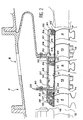
- Figure 2 is an enlarged view the downstream portion of the stator of this compressor
- the FIG. 2A a similar view of another embodiment possible of the invention
- Figures 3 and 4 are two cuts of the upstream and downstream parts of the compressor
- Figure 5 is an enlarged view of the upstream part of the compressor.
- a stator 7 surrounds the rotor 1 and comprises, in internal lining of a carcass 8, a portion 9 to which the invention relates and which consists of a support casing 10 and a ferrule 11 supported by the housing 10, turned towards the rotor 1 and which serves to delimit a ring vein 12 of gas flow in which the moving blade stages 6 and blade stages stationary 13 flow rectification, which are attached to the shell 11 and alternate with the floors previously mentioned.
- abradable 15 formed of a honeycomb structure or more generally of easy erosion, which is dug by ribs 16 opposite erected on the envelope 3 and which form with it a seal at labyrinth.
- the tips of the moving blades 6 are free of any equipment and end up close of the ferrule 11.
- the internal portion 9 of the stator 7 presents discontinuities, which are openings of air sampling from vein 12, noted by references 17, 18 and which give in rooms 19 and 20 established between the portion 9 and the carcass 8 and through which the air taken from the vein 12 to ventilate in particular the housing 10 and subject it to temperature and dilation thermal determined.
- the inside of the rotor 1 is it also ventilated, firstly through a piercing 21 of the casing 3 located upstream of the rotor 1 and by which fresh air, at approximately the same temperature as the one who enters the room 19, is sucked, then by another bore 22 of the casing 3, substantially to the right of the second opening 18.
- Sectors 23 and 23 'adjacent are united by flexible tongues 24 sealing, extending into grooves longitudinal edges of the sectors and joining by their ends 25, between circles of sectors 23 and 23 'consecutive; and by other tabs 26 flexible established in grooves purely or obliquely radial edges of sectors 23 and 23 ', and extending from the first tongues 24 to the housing 10.
- This arrangement effectively prevents the gases, very hot there, from vein 12 to flee between sectors 23 and 23 'to reach the housing 10 and risk of damaging it.
- the tabs 24 and 26 isolate empty volumes 27 (which can also be filled with insulation at the heat) that appear between each of the circles of sectors 23 and 23 'and associated rings 28 of the housing 10.
- each of them comprises a rear lip 31 protruding towards inside and back, and that is enclosed between a lip 32 of one of the rings 28, located radially outward, and a lip 33 or 33 ' pointing forward and established either in front of sectors 23, that is to the front of ring 28 located on further downstream; and sectors 23 and 23 'include still an outer lip 34 at the front, which cooperates with lips 33 to enclose lips 31 and 32 directed to the rear.
- Sectors 23 ' differ in that they only include one lip unique at the front, bearing the reference 35 and oriented towards the rear, and which is housed in a groove 36 of the ring 28 located furthest forward.
- This mode assembly is simpler than a mode inspired by more traditional ring fastening designs of ferrule, illustrated in Figure 2A, where the lips 31 and 32 are united by separate seals 37 with a cross-section staple and where the ferrule elements comprise a rib 38 relatively high ending in a lip 39 forward facing and housed in a groove of the adjacent ring; however, it is possible to adopt this less favorable design if desired.
- the 50 tenon nesting systems allow in all cases of linking sectors 23 and 23 'to rings 28 in the angular direction; many achievements are within the reach of the skilled person.
- the mode of linking sectors 23 and 23 'to Rings 28 is quite flexible and absorbs deformations without receiving strong constraints.
- the rings 28 are preferably continuous on the circumference for give a simpler structure and a better mechanical resistance.
- a nickel-based alloy, type INCO718, high coefficient of expansion can be used for this downstream part of the compressor.
- the housing 10 is at this place composed of rings 40, joined together by bolts 42 enclosing flanges 41 which the end, as well as the carcass 8, in the manner of rings 28; but these rings 40 still include protuberances 43 and 43 'radially on the inside, which open out on the 12th vein of airflow and are therefore exposed to its temperature. Two of these protuberances 43 are wide enough to extend in front of a stage of moving blades 6 respective.
- the ferrule 11 is here formed at a time by the protuberances 43 and 43 'and by rings 44 support of the stationary vanes 13; the rings 44 finish at the front and back by lips 45 who enter grooves of the growths 43 and 43 '.
- mechanical systems 46 with interlocking tenon join the rings 40 to the rings 44 concentric against mutual rotations.
- the major difference with downstream design is that the rings 44 are continuous on a circumference while as the rings 40. It is estimated that, as heating up are less important upstream, and that the temperature differences between the housing 10 and the ferrule 11 are less important also it is more simple and more advantageous to have a structure similar for both, the risks of deformation and excessive stress being reduced.
- the material used has a coefficient of dilation less than that used for build the downstream of the crankcase, because we observe that Slower dilations than these materials undergo regulate a little the evolution of the dilatation during transient phases and allow finally better control games at the end of the blade blades 6.
- An alloy of the Inconel 909 type may be recommended or an intermetallic type TiAl.
- the rotor 1 can be built in a material whose coefficient of expansion is close of that used for the stator rings 40 in look, for example a titanium alloy.
Landscapes
- Engineering & Computer Science (AREA)
- Mechanical Engineering (AREA)
- General Engineering & Computer Science (AREA)
- Structures Of Non-Positive Displacement Pumps (AREA)
Description
Claims (8)
- Stator de compresseur muni d'une ventilation en amont (17, 19) d'air de refroidissement et une ventilation en aval (18, 20) d'air plus chaud qu'à la ventilation amont, amont et aval étant définis par rapport au sens normal de circulation du flux d'air principal et comprenant une virole (11) délimitant une veine (12) d'écoulement de gaz, caractérisé en ce qu'il comprend une première portion de virole, soumise à la ventilation en amont (17), à structure annulaire (44) continue sur une circonférence et en un premier matériau, et une deuxième portion de virole, soumise à la ventilation aval, à structure formée de secteurs (23) angulaires juxtaposés et en un deuxième matériau ayant un coefficient de dilatation plus grand que le premier matériau.
- Stator suivant la revendication 1, caractérisé en ce que les premier et deuxième matériaux sont choisis, respectivement, parmi un groupe de matériaux à coefficient de dilatation plus bas tels que TA6V et alliages de titane, INC0909, intermétalliques du type TiAl, ayant un coefficient moyen de dilatation linéique inférieur à 10.10-6 m par degré ; et parmi un groupe de matériaux à coefficient de dilatation plus grand tels que des alliages à base de nickel du type INC0718, RENE77 et dérivés, ayant un coefficient moyen de dilatation linéique voisin de 15.10-6 m par degré.
- Stator suivant l'une quelconque des revendications 1 ou 2, caractérisé en ce qu'il comprend un carter (10) soutenant la virole (11), le carter (10) délimitant une chambre (19) appartenant à la ventilation amont et une chambre (20) appartenant à la ventilation aval, et en ce que le carter est formé en structure annulaire continue (28, 40) sur une circonférence devant les deux chambres.
- Stator suivant la revendication 3, caractérisé en ce que le carter (10) est composé d'anneaux (28, 40) venant en prolongement et formant un ensemble continu devant la première portion de virole et devant la deuxième portion de virole.
- Stator suivant la revendication 4, caractérisé en ce que les anneaux du carter devant la deuxième partie de la virole sont respectivement associés à des ensembles annulaires des secteurs juxtaposés (23, 23') de la virole, et les secteurs (23) comprennent pour la plupart une paire de lèvres concentriques (33, 34) à une extrémité, enserrant une lèvre (31) d'une extrémité opposée de secteurs (23, 23') d'un ensemble annulaire voisin et une lèvre (32) d'un anneau du carter associé audit ensemble annulaire voisin.
- Stator suivant la revendication 3, caractérisé en ce que les anneaux du carter devant la première partie de la virole présentent des excroissances (43, 43') s'étendant entre les anneaux de virole et délimitant aussi la veine d'écoulement (12), les anneaux de virole étant imbriqués entre les excroissances.
- Stator suivant l'une quelconque des revendications 1 à 6, caractérisé en ce que les secteurs (23, 23') sont réunis par des languettes souples (24, 26).
- Stator suivant l'une quelconque des revendication 1 à 7, caractérisé en ce que les première et deuxième portions de virole sont situées devant des portions d'un rotor (1) respectivement construites dans le premier matériau et le second matériau.
Applications Claiming Priority (2)
| Application Number | Priority Date | Filing Date | Title |
|---|---|---|---|
| FR9907315A FR2794816B1 (fr) | 1999-06-10 | 1999-06-10 | Stator de compresseur a haute pression |
| FR9907315 | 1999-06-10 |
Publications (2)
| Publication Number | Publication Date |
|---|---|
| EP1059420A1 EP1059420A1 (fr) | 2000-12-13 |
| EP1059420B1 true EP1059420B1 (fr) | 2004-12-08 |
Family
ID=9546602
Family Applications (1)
| Application Number | Title | Priority Date | Filing Date |
|---|---|---|---|
| EP00401609A Expired - Lifetime EP1059420B1 (fr) | 1999-06-10 | 2000-06-08 | Stator de compresseur à haute pression |
Country Status (5)
| Country | Link |
|---|---|
| US (1) | US6390771B1 (fr) |
| EP (1) | EP1059420B1 (fr) |
| JP (1) | JP4124552B2 (fr) |
| DE (1) | DE60016505T2 (fr) |
| FR (1) | FR2794816B1 (fr) |
Families Citing this family (25)
| Publication number | Priority date | Publication date | Assignee | Title |
|---|---|---|---|---|
| EP1118806A1 (fr) * | 2000-01-20 | 2001-07-25 | Siemens Aktiengesellschaft | Structure de paroi sous charge thermique et méthode pour fermer des fentes dans une tel structure |
| FR2866079B1 (fr) | 2004-02-05 | 2006-03-17 | Snecma Moteurs | Diffuseur pour turboreacteur |
| DE102004016222A1 (de) * | 2004-03-26 | 2005-10-06 | Rolls-Royce Deutschland Ltd & Co Kg | Anordnung zur selbsttätigen Laufspalteinstellung bei einer zwei- oder mehrstufigen Turbine |
| FR2887939B1 (fr) * | 2005-06-29 | 2016-09-30 | Soc Nat D'etude Et De Construction De Moteurs D'aviation Snecma | Compresseur multi-etages de turbomachine |
| US7604455B2 (en) * | 2006-08-15 | 2009-10-20 | Siemens Energy, Inc. | Rotor disc assembly with abrasive insert |
| US7704038B2 (en) * | 2006-11-28 | 2010-04-27 | General Electric Company | Method and apparatus to facilitate reducing losses in turbine engines |
| FR2913051B1 (fr) | 2007-02-28 | 2011-06-10 | Snecma | Etage de turbine dans une turbomachine |
| FR2925109B1 (fr) * | 2007-12-14 | 2015-05-15 | Snecma | Module de turbomachine muni d'un dispositif d'amelioration des jeux radiaux |
| FR2925108B1 (fr) * | 2007-12-14 | 2013-05-03 | Snecma | Module de turbomachine muni d'un dispositif d'amelioration des jeux radiaux |
| WO2009123301A2 (fr) * | 2008-03-31 | 2009-10-08 | Mitsubishi Heavy Industries, Ltd. | Machine rotative |
| FR2935625B1 (fr) * | 2008-09-05 | 2011-09-09 | Snecma | Procede de fabrication d'une piece thermamecanique de revolution circulaire comportant un substrat porteur a base de titane revetu d'acier ou superalliage, carter de compresseur de turbomachine resistant au feu de titane |
| FR2935623B1 (fr) * | 2008-09-05 | 2011-12-09 | Snecma | Procede de fabrication d'une piece thermomecanique de revolution circulaire comportant un substrat porteur a base de titane revetu d'acier ou superalliage, carter de compresseur de turbomachine resistant au feu de titane |
| FR2935624B1 (fr) * | 2008-09-05 | 2011-06-10 | Snecma | Procede de fabrication d'une piece thermomecanique de revolution circulaire comportant un substrat porteur a base de titane revetu d'acier ou superalliage, carter de compresseur de turbomachine resistant au feu de titane |
| US8613593B2 (en) * | 2008-12-30 | 2013-12-24 | Rolls-Royce North American Technologies Inc. | Engine case system for a gas turbine engine |
| JP4856257B2 (ja) * | 2010-03-24 | 2012-01-18 | 川崎重工業株式会社 | タービンロータのシール構造 |
| US8714908B2 (en) * | 2010-11-05 | 2014-05-06 | General Electric Company | Shroud leakage cover |
| US9091172B2 (en) | 2010-12-28 | 2015-07-28 | Rolls-Royce Corporation | Rotor with cooling passage |
| US9115600B2 (en) * | 2011-08-30 | 2015-08-25 | Siemens Energy, Inc. | Insulated wall section |
| US9234463B2 (en) | 2012-04-24 | 2016-01-12 | United Technologies Corporation | Thermal management system for a gas turbine engine |
| US20140286766A1 (en) * | 2012-09-11 | 2014-09-25 | General Electric Company | Compressor Casing Assembly Providing Access To Compressor Blade Sealing Assembly |
| US10539153B2 (en) * | 2017-03-14 | 2020-01-21 | General Electric Company | Clipped heat shield assembly |
| US10767485B2 (en) * | 2018-01-08 | 2020-09-08 | Raytheon Technologies Corporation | Radial cooling system for gas turbine engine compressors |
| US20200072070A1 (en) * | 2018-09-05 | 2020-03-05 | United Technologies Corporation | Unified boas support and vane platform |
| FR3086323B1 (fr) | 2018-09-24 | 2020-12-11 | Safran Aircraft Engines | Carter interne de turmomachine a isolation thermique amelioree |
| US11174742B2 (en) | 2019-07-19 | 2021-11-16 | Rolls-Royce Plc | Turbine section of a gas turbine engine with ceramic matrix composite vanes |
Family Cites Families (13)
| Publication number | Priority date | Publication date | Assignee | Title |
|---|---|---|---|---|
| DE1285255B (de) * | 1964-10-28 | 1968-12-12 | Bergmann Borsig Veb | Waermebeweglich aufgehaengte Leitgittersegmente von Axialgasturbinen |
| BE792224A (fr) * | 1971-12-01 | 1973-03-30 | Penny Robert N | Element composite long ayant un coefficient de dilatation lineaire effectif predetermine |
| GB1501916A (en) * | 1975-06-20 | 1978-02-22 | Rolls Royce | Matching thermal expansions of components of turbo-machines |
| DE3315914A1 (de) * | 1983-05-02 | 1984-11-08 | MTU Motoren- und Turbinen-Union München GmbH, 8000 München | Gasturbinentriebwerk mit einrichtungen zur schaufelspaltminimierung |
| FR2604750B1 (fr) * | 1986-10-01 | 1988-12-02 | Snecma | Turbomachine munie d'un dispositif de commande automatique des debits de ventilation de turbine |
| US5127794A (en) * | 1990-09-12 | 1992-07-07 | United Technologies Corporation | Compressor case with controlled thermal environment |
| US5160241A (en) * | 1991-09-09 | 1992-11-03 | General Electric Company | Multi-port air channeling assembly |
| FR2685936A1 (fr) * | 1992-01-08 | 1993-07-09 | Snecma | Dispositif de controle des jeux d'un carter de compresseur de turbomachine. |
| US5351478A (en) * | 1992-05-29 | 1994-10-04 | General Electric Company | Compressor casing assembly |
| FR2695164B1 (fr) * | 1992-08-26 | 1994-11-04 | Snecma | Turbomachine munie d'un dispositif empêchant une circulation longitudinale de gaz autour des étages d'aubes de redressement. |
| US5653581A (en) * | 1994-11-29 | 1997-08-05 | United Technologies Corporation | Case-tied joint for compressor stators |
| US5553999A (en) * | 1995-06-06 | 1996-09-10 | General Electric Company | Sealable turbine shroud hanger |
| US6109868A (en) * | 1998-12-07 | 2000-08-29 | General Electric Company | Reduced-length high flow interstage air extraction |
-
1999
- 1999-06-10 FR FR9907315A patent/FR2794816B1/fr not_active Expired - Fee Related
-
2000
- 2000-05-25 JP JP2000154077A patent/JP4124552B2/ja not_active Expired - Lifetime
- 2000-06-05 US US09/586,791 patent/US6390771B1/en not_active Expired - Lifetime
- 2000-06-08 EP EP00401609A patent/EP1059420B1/fr not_active Expired - Lifetime
- 2000-06-08 DE DE60016505T patent/DE60016505T2/de not_active Expired - Lifetime
Also Published As
| Publication number | Publication date |
|---|---|
| FR2794816B1 (fr) | 2001-07-06 |
| US6390771B1 (en) | 2002-05-21 |
| FR2794816A1 (fr) | 2000-12-15 |
| DE60016505D1 (de) | 2005-01-13 |
| JP2001012396A (ja) | 2001-01-16 |
| JP4124552B2 (ja) | 2008-07-23 |
| DE60016505T2 (de) | 2005-11-03 |
| EP1059420A1 (fr) | 2000-12-13 |
Similar Documents
| Publication | Publication Date | Title |
|---|---|---|
| EP1059420A1 (fr) | Stator de compresseur à haute pression | |
| CA2457892C (fr) | Carter de stator de turbomachine | |
| EP0967364B1 (fr) | Anneau de stator de turbine haute pression d'une turbomachine | |
| FR3072720B1 (fr) | Carter pour turbomachine comprenant une portion centrale en saillie relativement a deux portions laterales dans une region de jonction | |
| EP1571294B1 (fr) | Flasque-crochet annulaire pour un disque de rotor | |
| CA2644309C (fr) | Etancheite d'un anneau de rotor dans un etage de turbine | |
| FR2641033A1 (fr) | ||
| FR3011031A1 (fr) | Ensemble rotatif pour turbomachine | |
| FR2955898A1 (fr) | Etancheite amont d'un anneau en cmc dans une turbine de turbomachine | |
| FR2468738A1 (fr) | Organe d'etancheite pour une turbine a gaz | |
| CA2925438C (fr) | Ensemble rotatif pour turbomachine | |
| FR2593233A1 (fr) | Structure de joint d'etancheite pour un conduit de transition, destinee a etre mise en place entre les rotors de turbines haute pression et basse pression d'un moteur a plusieurs rotors | |
| EP2513428A1 (fr) | Etage de turbine dans une turbomachine | |
| FR3020408A1 (fr) | Ensemble rotatif pour turbomachine | |
| FR2690965A1 (fr) | Dispositif pour assurer l'étanchéité de pièces, notamment dans des turbomachines. | |
| EP0651139B1 (fr) | Turbomachine équipée de moyens de pilotage des jeux entre rotor et stator | |
| EP1519009A1 (fr) | Turboréacteur avec prélèvement d'air de cabine par tube à double rotule | |
| FR2534982A1 (fr) | Dispositif de controle des jeux d'un compresseur haute pression | |
| FR3067405A1 (fr) | Turbomachine et procede d'etancheite par soufflage d'air | |
| FR2895766A1 (fr) | Perfectionnements a un systeme de commande du jeu en bout d'ailette | |
| EP4208626A1 (fr) | Turbine pour turbomachine comprenant des clinquants de protection thermique | |
| FR2543219A1 (fr) | Assemblage de stator pouvant etre refroidi pour une turbine a gaz | |
| EP4041993B1 (fr) | Distributeur de turbine à aubage en composite à matrice céramique traversé par un circuit de ventilation métallique | |
| FR2953250A1 (fr) | Rotor de turbine d'une turbomachine son procede de fabrication et turbomachine equipee d'un tel rotor | |
| FR2847945A1 (fr) | Liaison entre fond arriere de chambre de combustion et tuyere de moteur fusee |
Legal Events
| Date | Code | Title | Description |
|---|---|---|---|
| PUAI | Public reference made under article 153(3) epc to a published international application that has entered the european phase |
Free format text: ORIGINAL CODE: 0009012 |
|
| 17P | Request for examination filed |
Effective date: 20000617 |
|
| AK | Designated contracting states |
Kind code of ref document: A1 Designated state(s): DE FR GB |
|
| AX | Request for extension of the european patent |
Free format text: AL;LT;LV;MK;RO;SI |
|
| AKX | Designation fees paid |
Free format text: DE FR GB |
|
| 17Q | First examination report despatched |
Effective date: 20031219 |
|
| GRAP | Despatch of communication of intention to grant a patent |
Free format text: ORIGINAL CODE: EPIDOSNIGR1 |
|
| GRAS | Grant fee paid |
Free format text: ORIGINAL CODE: EPIDOSNIGR3 |
|
| GRAA | (expected) grant |
Free format text: ORIGINAL CODE: 0009210 |
|
| AK | Designated contracting states |
Kind code of ref document: B1 Designated state(s): DE FR GB |
|
| REG | Reference to a national code |
Ref country code: GB Ref legal event code: FG4D Free format text: NOT ENGLISH |
|
| REF | Corresponds to: |
Ref document number: 60016505 Country of ref document: DE Date of ref document: 20050113 Kind code of ref document: P |
|
| GBT | Gb: translation of ep patent filed (gb section 77(6)(a)/1977) |
Effective date: 20050113 |
|
| RAP2 | Party data changed (patent owner data changed or rights of a patent transferred) |
Owner name: SNECMA |
|
| PLBE | No opposition filed within time limit |
Free format text: ORIGINAL CODE: 0009261 |
|
| STAA | Information on the status of an ep patent application or granted ep patent |
Free format text: STATUS: NO OPPOSITION FILED WITHIN TIME LIMIT |
|
| 26N | No opposition filed |
Effective date: 20050909 |
|
| REG | Reference to a national code |
Ref country code: FR Ref legal event code: CD |
|
| REG | Reference to a national code |
Ref country code: FR Ref legal event code: PLFP Year of fee payment: 16 |
|
| REG | Reference to a national code |
Ref country code: FR Ref legal event code: PLFP Year of fee payment: 17 |
|
| REG | Reference to a national code |
Ref country code: FR Ref legal event code: PLFP Year of fee payment: 18 |
|
| REG | Reference to a national code |
Ref country code: FR Ref legal event code: PLFP Year of fee payment: 19 |
|
| REG | Reference to a national code |
Ref country code: FR Ref legal event code: CD Owner name: SAFRAN AIRCRAFT ENGINES, FR Effective date: 20170719 |
|
| PGFP | Annual fee paid to national office [announced via postgrant information from national office to epo] |
Ref country code: DE Payment date: 20190521 Year of fee payment: 20 |
|
| PGFP | Annual fee paid to national office [announced via postgrant information from national office to epo] |
Ref country code: FR Payment date: 20190522 Year of fee payment: 20 |
|
| PGFP | Annual fee paid to national office [announced via postgrant information from national office to epo] |
Ref country code: GB Payment date: 20190522 Year of fee payment: 20 |
|
| REG | Reference to a national code |
Ref country code: DE Ref legal event code: R071 Ref document number: 60016505 Country of ref document: DE |
|
| REG | Reference to a national code |
Ref country code: GB Ref legal event code: PE20 Expiry date: 20200607 |
|
| PG25 | Lapsed in a contracting state [announced via postgrant information from national office to epo] |
Ref country code: GB Free format text: LAPSE BECAUSE OF EXPIRATION OF PROTECTION Effective date: 20200607 |