EP1059142A2 - Trägerplatte zum Aufbringen von Druck und zum Rückhalten eines Substrates - Google Patents
Trägerplatte zum Aufbringen von Druck und zum Rückhalten eines Substrates Download PDFInfo
- Publication number
- EP1059142A2 EP1059142A2 EP00303398A EP00303398A EP1059142A2 EP 1059142 A2 EP1059142 A2 EP 1059142A2 EP 00303398 A EP00303398 A EP 00303398A EP 00303398 A EP00303398 A EP 00303398A EP 1059142 A2 EP1059142 A2 EP 1059142A2
- Authority
- EP
- European Patent Office
- Prior art keywords
- rods
- substrate
- carrier head
- chamber
- polishing
- Prior art date
- Legal status (The legal status is an assumption and is not a legal conclusion. Google has not performed a legal analysis and makes no representation as to the accuracy of the status listed.)
- Withdrawn
Links
- 239000000758 substrate Substances 0.000 title claims abstract description 99
- 238000005498 polishing Methods 0.000 claims abstract description 64
- 239000012528 membrane Substances 0.000 claims description 33
- 238000007517 polishing process Methods 0.000 claims description 3
- 239000000126 substance Substances 0.000 abstract description 6
- 239000002002 slurry Substances 0.000 description 7
- 238000000034 method Methods 0.000 description 5
- KWYUFKZDYYNOTN-UHFFFAOYSA-M Potassium hydroxide Chemical compound [OH-].[K+] KWYUFKZDYYNOTN-UHFFFAOYSA-M 0.000 description 3
- 230000003247 decreasing effect Effects 0.000 description 3
- 239000002245 particle Substances 0.000 description 3
- 239000004734 Polyphenylene sulfide Substances 0.000 description 2
- VYPSYNLAJGMNEJ-UHFFFAOYSA-N Silicium dioxide Chemical compound O=[Si]=O VYPSYNLAJGMNEJ-UHFFFAOYSA-N 0.000 description 2
- 239000000853 adhesive Substances 0.000 description 2
- 230000001070 adhesive effect Effects 0.000 description 2
- 239000003795 chemical substances by application Substances 0.000 description 2
- 239000012530 fluid Substances 0.000 description 2
- 229920000069 polyphenylene sulfide Polymers 0.000 description 2
- 235000012431 wafers Nutrition 0.000 description 2
- XUIMIQQOPSSXEZ-UHFFFAOYSA-N Silicon Chemical compound [Si] XUIMIQQOPSSXEZ-UHFFFAOYSA-N 0.000 description 1
- 230000003750 conditioning effect Effects 0.000 description 1
- 230000008878 coupling Effects 0.000 description 1
- 238000010168 coupling process Methods 0.000 description 1
- 238000005859 coupling reaction Methods 0.000 description 1
- 239000008367 deionised water Substances 0.000 description 1
- 229910021641 deionized water Inorganic materials 0.000 description 1
- 230000008021 deposition Effects 0.000 description 1
- 239000013013 elastic material Substances 0.000 description 1
- 239000002783 friction material Substances 0.000 description 1
- 238000004519 manufacturing process Methods 0.000 description 1
- 229920001296 polysiloxane Polymers 0.000 description 1
- 238000003825 pressing Methods 0.000 description 1
- 229910052710 silicon Inorganic materials 0.000 description 1
- 239000010703 silicon Substances 0.000 description 1
- 239000000377 silicon dioxide Substances 0.000 description 1
- 235000012239 silicon dioxide Nutrition 0.000 description 1
- 239000007921 spray Substances 0.000 description 1
- 238000012876 topography Methods 0.000 description 1
- XLYOFNOQVPJJNP-UHFFFAOYSA-N water Chemical compound O XLYOFNOQVPJJNP-UHFFFAOYSA-N 0.000 description 1
Images


Classifications
-
- B—PERFORMING OPERATIONS; TRANSPORTING
- B24—GRINDING; POLISHING
- B24B—MACHINES, DEVICES, OR PROCESSES FOR GRINDING OR POLISHING; DRESSING OR CONDITIONING OF ABRADING SURFACES; FEEDING OF GRINDING, POLISHING, OR LAPPING AGENTS
- B24B37/00—Lapping machines or devices; Accessories
- B24B37/27—Work carriers
- B24B37/30—Work carriers for single side lapping of plane surfaces
Definitions
- the present invention relates generally to chemical mechanical polishing of substrates, and more particularly to a carrier head for chemical mechanical polishing.
- Integrated circuits are typically formed on substrates, particularly silicon wafers, by the sequential deposition of conductive, semiconductive or insulative layers. After each layer is deposited, it is etched to create circuitry features. As a series of layers are sequentially deposited and etched, the outer or uppermost surface of the substrate, i.e., the exposed surface of the substrate, becomes increasingly nonplanar. This nonplanar surface presents problems in the photolithographic steps of the integrated circuit fabrication process. Therefore, there is a need to periodically planarize the substrate surface.
- CMP Chemical mechanical polishing
- This planarization method typically requires that the substrate be mounted on a carrier or polishing head. The exposed surface of the substrate is placed against a polishing surface, e.g., a rotating polishing pad.
- the polishing pad may be either a "standard” or a fixed-abrasive pad.
- a standard polishing pad has a durable roughened surface, whereas a fixed-abrasive pad has abrasive particles held in a containment media.
- a polishing slurry, including at least one chemically-reactive agent, and abrasive particles, if a standard pad is used, is supplied to the surface of the polishing pad.
- the effectiveness of a CMP process may be measured by its polishing rate, and by the resulting finish (absence of small-scale roughness) and flatness (absence of large-scale topography) of the substrate surface.
- the polishing rate, finish and flatness are determined by the pad and slurry combination, the relative speed between the substrate and pad, and the force pressing the substrate against the pad.
- the invention is directed to a carrier head.
- the carrier head has a housing, a plurality of substantially independently movable rods, and a first chamber located between the rods and the housing.
- the chamber is pressurizable to force the rods into contact with a substrate and to surround the substrate to retain the substrate beneath the housing.
- Implementations of the invention may include the following features.
- a lower boundary of the first chamber may be defined by a flexible membrane attached to the housing, and the rods may be attached to the flexible membrane.
- the first chamber may apply pressure directly to the rods.
- the rods may have a circular or hexagonal cross-section, a longitudinal dimension of about 0.06 to 0.5 inches, and a cross-sectional dimension of about 0.03 to 0.25 inches.
- the longitudinal dimension of the rods may be about twice their cross-sectional dimension.
- the rods may be spaced apart by about 0.0005 to 0.005 inches.
- the rods may be positioned around a perimeter portion of the substrate during polishing, and the carrier head further may include a flexible membrane having a mounting surface to contact a central region of the substrate.
- a second chamber that is pressurizable to apply a load to the central region of the substrate may be located between the flexible membrane and the housing.
- the rods may be positioned substantially parallel to each other.
- the invention is directed to a carrier head to hold a substrate on a polishing surface.
- the carrier head has a housing defining a chamber, a flexible membrane defining a lower boundary of said chamber, and a bundle of independently movable rods secured to the flexible membrane. When a pressure within the chamber is increased, the rods and move into contact with the substrate and the polishing surface to apply a force to the substrate and retain the substrate substantially beneath the housing.
- the invention is directed to a method of polishing a substrate.
- a substrate is positioned between a polishing surface and a plurality of independently movable rods of a carrier head, and a pressure is applied to the plurality of rods.
- One group of rods contacts a back surface of the substrate, and a second group of rods contacts the polishing surface to surround the substrate to retain the substrate beneath the carrier head.
- the spacing between the retainer and the substrate can be reduced, thereby improving polishing uniformity near the edge of the substrate.
- the carrier head has a large tolerance for misalignment of the substrate at a loading station.
- the carrier head is also usable with substrates of different sizes and geometries.
- the CMP apparatus 20 includes a series of polishing stations 25 and a transfer station 27 for the loading and unloading of the substrates.
- Each polishing station 25 includes a rotatable platen 30 on which is placed a polishing pad 32. If substrate 10 is an eight-inch (200 millimeter) or twelve-inch (300 millimeter) diameter disk, then platen 30 and polishing pad 32 will be about twenty or thirty inches in diameter, respectively. Platen 30 and polishing pad 32 may also be about twenty inches in diameter if substrate 10 is a six-inch (150 millimeter) diameter disk.
- a platen drive motor (not shown) rotates platen 30 at thirty to two-hundred revolutions per minute, although lower or higher rotational speeds may be used.
- Each polishing station 25 may further include an associated pad conditioner apparatus 40 to maintain the abrasive condition of the polishing pad.
- a rotatable multi-head carousel 60 is supported by a center post 62 and rotated thereon about a carousel axis 64 by a carousel motor assembly (not shown).
- Multi-head carousel 60 includes four carrier head systems 70 mounted on a carousel support plate 66 at equal angular intervals about carousel axis 64. Three of the carrier head systems position substrates over the polishing stations. One of the carrier head systems receives a substrate from and delivers the substrate to the transfer station.
- the carousel motor may orbit carrier head systems 70, and the substrates attached thereto, about carousel axis 64 between the polishing stations and the transfer station.
- carrier head 100 includes a housing 102, a rod-backing membrane 104 secured to the housing, and an array or bundle 106 of independently vertically-movable rods 108 attached to the underside of the membrane.
- Housing 102 can be connected to drive shaft 74 to rotate therewith during polishing about an axis of rotation which is substantially perpendicular to the surface of the polishing pad during polishing.
- Housing 102 may be generally circular in shape to correspond to the circular configuration of the substrate to be polished.
- a vertical passage 112 may be formed through the housing to provide pneumatic control of the carrier head.
- Unillustrated O-rings may be used to form a fluid-tight seal between the passage through the housing and a corresponding passage through the drive shaft. Fluid coupling between the drive shaft and carrier head is discussed in pending U.S. Application Serial No. 08/861,260, filed May 21, assigned to the assignee of the present application, the entire disclosure of which is incorporated herein by references.
- Membrane 104 is a generally circular sheet formed of a flexible and elastic material, such as silicone. An edge 114 of membrane 104 can be secured to housing 102 to form a fluid-tight seal, e.g., by an unillustrated clamp, adhesive, or the like.
- the sealed volume between membrane 104 and housing 102 defines a loading chamber 110.
- Loading chamber 110 can be pressurized to apply a load, i.e., a downward pressure, to membrane 104 and thus to rods 108.
- a pump (not shown) may be fluidly connected to loading chamber 110 by passage 112 to control the pressure in the loading chamber and, thus, the load applied to the rods.
- the rods 108 are attached to membrane 104, e.g., by an adhesive or mechanical fasteners, to form bundle 106.
- the rods are arranged with their longitudinal axes generally parallel to each other and perpendicular to the plane of the polishing pad.
- the rods in bundle 106 are sufficiently densely packed that small gaps between individual rods do not affect the polishing uniformity, yet sufficiently loosely packed that the rods can slide vertically relative to each other.
- membrane 104 is sufficiently flexible that each rod can move vertically independently by at least the substrate thickness (about 27 mils for an "eight-inch" substrate).
- the underside of bundle 106 formed by the bottom surfaces of the individual rods provides a collection of individually vertically adjustable surfaces.
- rod bundle 106 provides the functions of both a retaining ring and a substrate backing member.
- substrate 10 is placed on polishing pad 32 beneath carrier head 100. Fluid is pumped into chamber 110 via passage 112 to force flexible membrane 118 and rods 108 downwardly.
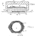
- the rods 108a positioned above substrate 10 (which are obscured by the substrate in the view of FIG. 5) press against the backside of the substrate.
- the rods 108b positioned outside the region directly above the substrate are forced into contact with the polishing pad and surround the substrate.
- frictional forces from the polishing pad will force the substrate against the sides of the "innermost" rods 108b, i.e, the rods adjacent the substrate.
- the rod bundle both applies pressure and retains the substrate beneath the carrier head. The closer the "fit" between the rods and the substrate, the less room the polishing pad has to decompress, thereby providing improved polishing uniformity at the substrate edge.
- the cross-sectional shape and dimensions of the rods are selected to provide a small gap with the substrate while ensuring that the rods can slide relative to each other. It should be noted that the greater the frictional forces between the rods, the more likely it is that the rods will "stick” rather than slide. Three main factors contribute to these frictional forces and the fit of the rods to the substrate: the spacing between the rods, the cross-sectional dimension (D) of the rods, and the contact area between the side surfaces or adjacent rods.
- the contact area between the side surfaces of the rods also depends on their cross-sectional shape. For example, circular rods will contact each other only along a relatively narrow strip, whereas hexagonal or square rods will contact each other across the entire face of the rod. Using a cross-sectional shape that provides a larger contact area (e.g., by using a hexagonal rod instead of a circular rod) will improve the substrate fit, but will also increase the frictional forces. Conversely, decreasing the contact area will result in a worse substrate fit, but will decrease the frictional forces. Circular rods may be used in a densely packed bundle to reduce the frictional forces, whereas hexagonal rods may be used in a loosely packed bundle to improve the substrate fit.
- the carrier head is self-fitting to substrates having different diameters and different geometries (e.g., flatted or notched wafers). Since the rods are self-fitting, it should be possible to significantly reduce the gap between the substrate and retainer edge as compared to a conventional retaining ring (shown by solid line A in FIG. 5). Furthermore, the carrier head has a large tolerance for misalignment of the substrate. When the substrate is loaded at the transfer station or at a polishing station, the rods will adjust to surround the substrate, regardless of its horizontal position. In addition, the pressure on the top surface of the rods will cause them to move downwardly as their bottom surfaces are worn away. Thus, the rod bundle provides a retainer that is less subject to uneven wear patterns.
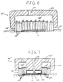
- carrier head 100' does not include a flexible membrane. Instead, pressure is applied directly to the top surfaces of rods 108'. When the carrier head is lifted away from the polishing pad, vacuum is applied to chamber 110' to hold the bundle in the carrier head. In this implementation, the vacuum source needs a sufficiently high flow rate to compensate for pressure leaks between the rods.
- carrier head 100'' includes both a flexible membrane 120 that contacts a back surface off the substrate, and a bundle 106'' of rods 108''.
- rods 108'' may be positioned in an annular region around membrane 120.
- a lower surface 122 of membrane 120 provides a mounting surface to apply pressure to a central region of the substrate.
- Rods 108'' function as the retainer and apply pressure to a perimeter region of the substrate.
- the volume between rods 108'' and housing 102'' defines an annular first pressurizable chamber 110'', and a first pump (not shown) may be fluidly connected to chamber 110'' by passage 112'' to control the pressure in the chamber and thus the downward force on rods 108''.
- the sealed volume between flexible membrane 120 and housing 102'' defines a second pressurizable chamber 124.
- a second pump (not shown) may be fluidly connected to chamber 124 by a passage 126 in housing 102'' to control the pressure in chamber 124 and thus the downward force of flexible membrane 120 on the substrate.
- chamber 124 may be evacuated to pull flexible membrane 120 upwardly and thereby vacuum-chuck the substrate to the carrier head.
Landscapes
- Engineering & Computer Science (AREA)
- Mechanical Engineering (AREA)
- Finish Polishing, Edge Sharpening, And Grinding By Specific Grinding Devices (AREA)
- Mechanical Treatment Of Semiconductor (AREA)
Applications Claiming Priority (2)
| Application Number | Priority Date | Filing Date | Title |
|---|---|---|---|
| US09/330,243 US6050882A (en) | 1999-06-10 | 1999-06-10 | Carrier head to apply pressure to and retain a substrate |
| US330243 | 1999-06-10 |
Publications (2)
| Publication Number | Publication Date |
|---|---|
| EP1059142A2 true EP1059142A2 (de) | 2000-12-13 |
| EP1059142A3 EP1059142A3 (de) | 2003-03-12 |
Family
ID=23288908
Family Applications (1)
| Application Number | Title | Priority Date | Filing Date |
|---|---|---|---|
| EP00303398A Withdrawn EP1059142A3 (de) | 1999-06-10 | 2000-04-20 | Trägerplatte zum Aufbringen von Druck und zum Rückhalten eines Substrates |
Country Status (3)
| Country | Link |
|---|---|
| US (2) | US6050882A (de) |
| EP (1) | EP1059142A3 (de) |
| JP (1) | JP2000354959A (de) |
Families Citing this family (39)
| Publication number | Priority date | Publication date | Assignee | Title |
|---|---|---|---|---|
| US6413149B1 (en) * | 1998-04-28 | 2002-07-02 | Ebara Corporation | Abrading plate and polishing method using the same |
| US6422927B1 (en) * | 1998-12-30 | 2002-07-23 | Applied Materials, Inc. | Carrier head with controllable pressure and loading area for chemical mechanical polishing |
| US6050882A (en) | 1999-06-10 | 2000-04-18 | Applied Materials, Inc. | Carrier head to apply pressure to and retain a substrate |
| US6494774B1 (en) * | 1999-07-09 | 2002-12-17 | Applied Materials, Inc. | Carrier head with pressure transfer mechanism |
| US6722963B1 (en) * | 1999-08-03 | 2004-04-20 | Micron Technology, Inc. | Apparatus for chemical-mechanical planarization of microelectronic substrates with a carrier and membrane |
| US6290584B1 (en) * | 1999-08-13 | 2001-09-18 | Speedfam-Ipec Corporation | Workpiece carrier with segmented and floating retaining elements |
| EP1092504B1 (de) * | 1999-10-15 | 2005-12-07 | Ebara Corporation | Verfahren und Gerät zum Polieren eines Werkstückes |
| JP3753577B2 (ja) | 1999-11-16 | 2006-03-08 | 株式会社荏原製作所 | 基板保持装置及び該基板保持装置を備えたポリッシング装置 |
| US6663466B2 (en) * | 1999-11-17 | 2003-12-16 | Applied Materials, Inc. | Carrier head with a substrate detector |
| US6726537B1 (en) * | 2000-04-21 | 2004-04-27 | Agere Systems Inc. | Polishing carrier head |
| US6375550B1 (en) * | 2000-06-05 | 2002-04-23 | Lsi Logic Corporation | Method and apparatus for enhancing uniformity during polishing of a semiconductor wafer |
| GB2379626A (en) * | 2000-06-08 | 2003-03-19 | Speedfam Ipec Corp | Orbital polishing apparatus |
| DK1310502T3 (da) | 2000-08-10 | 2009-09-07 | Takeda Pharmaceutical | Phosphonocephem-forbindelse |
| US6652362B2 (en) * | 2000-11-23 | 2003-11-25 | Samsung Electronics Co., Ltd. | Apparatus for polishing a semiconductor wafer and method therefor |
| US6790763B2 (en) * | 2000-12-04 | 2004-09-14 | Ebara Corporation | Substrate processing method |
| US6769973B2 (en) * | 2001-05-31 | 2004-08-03 | Samsung Electronics Co., Ltd. | Polishing head of chemical mechanical polishing apparatus and polishing method using the same |
| US6863771B2 (en) * | 2001-07-25 | 2005-03-08 | Micron Technology, Inc. | Differential pressure application apparatus for use in polishing layers of semiconductor device structures and methods |
| KR100416808B1 (ko) * | 2002-02-04 | 2004-01-31 | 삼성전자주식회사 | 반도체소자 제조용 씨엠피장치의 연마헤드 및 이를 구비한씨엠피장치 |
| KR100506934B1 (ko) * | 2003-01-10 | 2005-08-05 | 삼성전자주식회사 | 연마장치 및 이를 사용하는 연마방법 |
| KR100586018B1 (ko) * | 2004-02-09 | 2006-06-01 | 삼성전자주식회사 | 연마 헤드용 플렉서블 멤브레인 및 이를 포함하는 연마 장치 |
| US20060128540A1 (en) * | 2004-12-10 | 2006-06-15 | Engle Vincent K | Apparatus for circuit and other fitness training |
| US8845394B2 (en) | 2012-10-29 | 2014-09-30 | Wayne O. Duescher | Bellows driven air floatation abrading workholder |
| US9199354B2 (en) | 2012-10-29 | 2015-12-01 | Wayne O. Duescher | Flexible diaphragm post-type floating and rigid abrading workholder |
| US9039488B2 (en) | 2012-10-29 | 2015-05-26 | Wayne O. Duescher | Pin driven flexible chamber abrading workholder |
| US9011207B2 (en) | 2012-10-29 | 2015-04-21 | Wayne O. Duescher | Flexible diaphragm combination floating and rigid abrading workholder |
| US9604339B2 (en) | 2012-10-29 | 2017-03-28 | Wayne O. Duescher | Vacuum-grooved membrane wafer polishing workholder |
| US9233452B2 (en) | 2012-10-29 | 2016-01-12 | Wayne O. Duescher | Vacuum-grooved membrane abrasive polishing wafer workholder |
| US8998677B2 (en) | 2012-10-29 | 2015-04-07 | Wayne O. Duescher | Bellows driven floatation-type abrading workholder |
| US8998678B2 (en) | 2012-10-29 | 2015-04-07 | Wayne O. Duescher | Spider arm driven flexible chamber abrading workholder |
| US9620953B2 (en) | 2013-03-25 | 2017-04-11 | Wen Technology, Inc. | Methods providing control for electro-permanent magnetic devices and related electro-permanent magnetic devices and controllers |
| US10734149B2 (en) | 2016-03-23 | 2020-08-04 | Wen Technology Inc. | Electro-permanent magnetic devices including unbalanced switching and permanent magnets and related methods and controllers |
| KR101966952B1 (ko) * | 2017-07-06 | 2019-04-18 | 주식회사 케이씨텍 | 슬러리 공급 유닛 및 이를 구비하는 기판 연마 장치 |
| US10926378B2 (en) | 2017-07-08 | 2021-02-23 | Wayne O. Duescher | Abrasive coated disk islands using magnetic font sheet |
| KR102796016B1 (ko) * | 2019-07-12 | 2025-04-17 | 삼성디스플레이 주식회사 | 화학 기계적 연마 장치, 화학 기계적 연마 방법 및 이를 이용한 표시장치 제조 방법 |
| US11691241B1 (en) * | 2019-08-05 | 2023-07-04 | Keltech Engineering, Inc. | Abrasive lapping head with floating and rigid workpiece carrier |
| US11325223B2 (en) * | 2019-08-23 | 2022-05-10 | Applied Materials, Inc. | Carrier head with segmented substrate chuck |
| US11511390B2 (en) * | 2019-08-30 | 2022-11-29 | Applied Materials, Inc. | Pivotable substrate retaining ring |
| US11660721B2 (en) | 2021-02-18 | 2023-05-30 | Applied Materials, Inc. | Dual loading retaining ring |
| US20230063687A1 (en) * | 2021-08-27 | 2023-03-02 | Taiwan Semiconductor Manufacturing Company Limited | Apparatus for polishing a wafer |
Family Cites Families (11)
| Publication number | Priority date | Publication date | Assignee | Title |
|---|---|---|---|---|
| JPH0387559U (de) * | 1989-12-18 | 1991-09-05 | ||
| JPH0740236A (ja) * | 1993-07-26 | 1995-02-10 | Hitachi Ltd | 多層配線基板の平坦化加工方法 |
| US5658183A (en) * | 1993-08-25 | 1997-08-19 | Micron Technology, Inc. | System for real-time control of semiconductor wafer polishing including optical monitoring |
| JPH07241764A (ja) * | 1994-03-04 | 1995-09-19 | Fujitsu Ltd | 研磨装置と研磨方法 |
| JP3550180B2 (ja) * | 1994-04-28 | 2004-08-04 | 同和鉱業株式会社 | ウェハの搬送方法および搬送装置 |
| JPH08257901A (ja) * | 1995-03-22 | 1996-10-08 | Ebara Corp | トップリング装置 |
| US5720845A (en) * | 1996-01-17 | 1998-02-24 | Liu; Keh-Shium | Wafer polisher head used for chemical-mechanical polishing and endpoint detection |
| JP3795128B2 (ja) * | 1996-02-27 | 2006-07-12 | 株式会社荏原製作所 | ポリッシング装置 |
| US5662518A (en) * | 1996-05-03 | 1997-09-02 | Coburn Optical Industries, Inc. | Pneumatically assisted unidirectional conformal tool |
| US5888120A (en) * | 1997-09-29 | 1999-03-30 | Lsi Logic Corporation | Method and apparatus for chemical mechanical polishing |
| US6050882A (en) | 1999-06-10 | 2000-04-18 | Applied Materials, Inc. | Carrier head to apply pressure to and retain a substrate |
-
1999
- 1999-06-10 US US09/330,243 patent/US6050882A/en not_active Expired - Lifetime
-
2000
- 2000-02-24 JP JP2000047787A patent/JP2000354959A/ja active Pending
- 2000-03-02 US US09/517,199 patent/US6220944B1/en not_active Expired - Fee Related
- 2000-04-20 EP EP00303398A patent/EP1059142A3/de not_active Withdrawn
Also Published As
| Publication number | Publication date |
|---|---|
| JP2000354959A (ja) | 2000-12-26 |
| US6220944B1 (en) | 2001-04-24 |
| EP1059142A3 (de) | 2003-03-12 |
| US6050882A (en) | 2000-04-18 |
Similar Documents
| Publication | Publication Date | Title |
|---|---|---|
| US6050882A (en) | Carrier head to apply pressure to and retain a substrate | |
| US6431968B1 (en) | Carrier head with a compressible film | |
| US6036587A (en) | Carrier head with layer of conformable material for a chemical mechanical polishing system | |
| US6165058A (en) | Carrier head for chemical mechanical polishing | |
| US6494774B1 (en) | Carrier head with pressure transfer mechanism | |
| US6277014B1 (en) | Carrier head with a flexible membrane for chemical mechanical polishing | |
| US6368191B1 (en) | Carrier head with local pressure control for a chemical mechanical polishing apparatus | |
| EP1029633B1 (de) | Trägerplatte mit einstellbarem Druck und einstellbarer Oberfläche für eine chemisch-mechanische Poliervorrichtung | |
| US6776694B2 (en) | Methods for carrier head with multi-part flexible membrane | |
| US6722965B2 (en) | Carrier head with flexible membranes to provide controllable pressure and loading area | |
| US5964653A (en) | Carrier head with a flexible membrane for a chemical mechanical polishing system | |
| EP1133380B1 (de) | Trägerplatte mit randsteuerung für chemisch-mechanisches polieren | |
| US6358121B1 (en) | Carrier head with a flexible membrane and an edge load ring | |
| US6361419B1 (en) | Carrier head with controllable edge pressure | |
| US6244942B1 (en) | Carrier head with a flexible membrane and adjustable edge pressure | |
| US6143127A (en) | Carrier head with a retaining ring for a chemical mechanical polishing system | |
| KR20010033796A (ko) | 화학-기계적 연마 장치용 착탈식 보유 링을 갖춘 캐리어헤드 | |
| WO2000013851A1 (en) | A carrier head for chemical mechanical polishing a substrate | |
| US6855043B1 (en) | Carrier head with a modified flexible membrane | |
| KR20010039710A (ko) | 변조된 가요성 막을 가진 캐리어 헤드 |
Legal Events
| Date | Code | Title | Description |
|---|---|---|---|
| PUAI | Public reference made under article 153(3) epc to a published international application that has entered the european phase |
Free format text: ORIGINAL CODE: 0009012 |
|
| AK | Designated contracting states |
Kind code of ref document: A2 Designated state(s): AT BE CH CY DE DK ES FI FR GB GR IE IT LI LU MC NL PT SE |
|
| AX | Request for extension of the european patent |
Free format text: AL;LT;LV;MK;RO;SI |
|
| PUAL | Search report despatched |
Free format text: ORIGINAL CODE: 0009013 |
|
| AK | Designated contracting states |
Kind code of ref document: A3 Designated state(s): AT BE CH CY DE DK ES FI FR GB GR IE IT LI LU MC NL PT SE Designated state(s): AT BE CH CY DE DK ES FI FR GB GR IE IT LI LU MC NL PT SE |
|
| AX | Request for extension of the european patent |
Extension state: AL LT LV MK RO SI |
|
| AKX | Designation fees paid | ||
| REG | Reference to a national code |
Ref country code: DE Ref legal event code: 8566 |
|
| STAA | Information on the status of an ep patent application or granted ep patent |
Free format text: STATUS: THE APPLICATION IS DEEMED TO BE WITHDRAWN |
|
| 18D | Application deemed to be withdrawn |
Effective date: 20030913 |