EP1059074B1 - Anlage zum Transport von verletzten Personen - Google Patents
Anlage zum Transport von verletzten Personen Download PDFInfo
- Publication number
- EP1059074B1 EP1059074B1 EP00890070A EP00890070A EP1059074B1 EP 1059074 B1 EP1059074 B1 EP 1059074B1 EP 00890070 A EP00890070 A EP 00890070A EP 00890070 A EP00890070 A EP 00890070A EP 1059074 B1 EP1059074 B1 EP 1059074B1
- Authority
- EP
- European Patent Office
- Prior art keywords
- rescue
- stretcher
- sled
- injured
- accommodating
- Prior art date
- Legal status (The legal status is an assumption and is not a legal conclusion. Google has not performed a legal analysis and makes no representation as to the accuracy of the status listed.)
- Expired - Lifetime
Links
- 238000009434 installation Methods 0.000 title claims 2
- 238000010168 coupling process Methods 0.000 claims description 7
- 230000008878 coupling Effects 0.000 claims description 6
- 238000005859 coupling reaction Methods 0.000 claims description 6
- 239000012780 transparent material Substances 0.000 claims description 2
- 108010066114 cabin-2 Proteins 0.000 description 9
- 238000011084 recovery Methods 0.000 description 3
- 239000002131 composite material Substances 0.000 description 1
- 238000010276 construction Methods 0.000 description 1
- 230000003111 delayed effect Effects 0.000 description 1
Images

Classifications
-
- A—HUMAN NECESSITIES
- A61—MEDICAL OR VETERINARY SCIENCE; HYGIENE
- A61G—TRANSPORT, PERSONAL CONVEYANCES, OR ACCOMMODATION SPECIALLY ADAPTED FOR PATIENTS OR DISABLED PERSONS; OPERATING TABLES OR CHAIRS; CHAIRS FOR DENTISTRY; FUNERAL DEVICES
- A61G1/00—Stretchers
- A61G1/06—Supports for stretchers, e.g. to be placed in or on vehicles
-
- A—HUMAN NECESSITIES
- A61—MEDICAL OR VETERINARY SCIENCE; HYGIENE
- A61G—TRANSPORT, PERSONAL CONVEYANCES, OR ACCOMMODATION SPECIALLY ADAPTED FOR PATIENTS OR DISABLED PERSONS; OPERATING TABLES OR CHAIRS; CHAIRS FOR DENTISTRY; FUNERAL DEVICES
- A61G3/00—Ambulance aspects of vehicles; Vehicles with special provisions for transporting patients or disabled persons, or their personal conveyances, e.g. for facilitating access of, or for loading, wheelchairs
Definitions
- the subject invention relates to a device for the transport of injured persons, in particular for the transport of injured winter athletes, by a rescue cabin, which has a device for its coupling is formed with a snow groomer.
- the known require Rescue measures so far a high organizational effort, as a rescue sled from a certain place to which he turned off is to be brought to the scene of the accident.
- the rescue operation can be very difficult and especially delayed.
- the removal of the injured person requires the rescue sled a high physical and psychological burden.
- the subject invention has for its object to provide such a structural design, which can be used in a simple manner and within a short time.
- the rescue cage is formed with at least two hooks open downwards, through which the upper edge of a grooving vehicle attached to the snow groomer is übergreifbar and that the hooks are formed with locking bolts through which the rescue cabin can be attached to the Räumschar.
- the Räumschar is provided in the region of its upper edge with the hook associated apertures, in which the locking bolt can be used.
- Such rescue cabins can be parked in areas in which they may be needed, especially on the edges of ski slopes, and in the event that a rescue mission is required, be coupled to the groomer closest to the scene of the accident and by This piste vehicle to be promoted to the scene of the accident.
- the rescue cabin with an intermediate a closed position and an open position pivotable cover educated.
- the rescue cabin can be equipped with a facility for Recording of a stretcher or a rescue slide to be formed. moreover can in the rescue cabin under the facility to accommodate the Stretcher or rescue sled a space for holding objects, in particular of the injured person's equipment, be provided.
- the means for receiving the stretcher or the Rescue slide trained in a conventional manner with rails, opposite which the stretcher and the rescue slide and slidably is lockable.
- a room for a companion be provided in the rescue cabin next to the facility for Recording the stretcher or the rescue slide in their longitudinal direction.
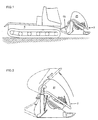
- a snow groomer 1 which has a Räumschar 11, to which a rescue cage 2 is coupled.
- the rescue cabin 2 is formed with a cover 21, which, as shown in Fig. 2, from a rescue cabin 2 closing position in an open position is pivotable, whereby the rescue cage is accessible.
- the rescue cage 2 has transverse to the direction of travel of the snow groomer 1 a length of about 3 m, which it is sufficiently long, on the one hand a stretcher 22 or a Rescue sled 23 for an injured person and on the other hand a companion, e.g. a paramedic, to offer space.
- a rescue cabin 2 with a stretcher 22 shown In Fig. 3a is a rescue cabin 2 with a stretcher 22 shown, whereas in Fig. 3b, a rescue cage 2 with a rescue slide 23 is shown. It is hereby referred to that at such accident sites, to which an access by a snow groomer is not possible, the use of a rescue slide 23 may be required can. Regardless, the further transport with the snow groomer therefore advantageous because it is much gentler than by means of a rescue sled There is also room for one accompanying person in the rescue cabin is available.
- the rescue cage 2 is formed with guides along which the stretcher 22 and the rescue carriage 23 are displaceable. Below the guides there is a space 24 for receiving objects, e.g. of the Equipment of the injured athlete.
- the cover 21 of the rescue cage 2 is made of transparent material, in particular of a transparent glass-plastic composite material, produced. This is the required view both in the interior of the rescue cabin 2 and out of this allows. In addition, it is also possible to see through the rescue cabin 2 be through which the rescue cabin 2, the view of the driver of the snow groomer 1 is not obstructed.
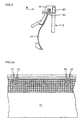
- This coupling device 4 consists of two on a support frame 20 of the rescue cabin 2 arranged hook 41, which locking bolt 42 are assigned. As soon as these hooks 41 on the upper edge of the Räumschar 11 of the snow groomer 1 were placed and by means of the locking bolt 42, which the Räumschar 11 in breakthroughs have been fixed, is the rescue cabin 2 attached to the piste device 1.
- Such rescue cabins can be located in areas where they are needed may be parked, especially on the edges of ski slopes, in the event that a rescue mission is required, to that piste vehicle, which is closest to the accident site, immediately coupled be promoted to the scene of the accident by means of this snow groomer can. After the injured person spent in the rescue cabin It becomes an emergency vehicle by means of the snow groomer brought to a rescue helicopter.
Landscapes
- Health & Medical Sciences (AREA)
- Public Health (AREA)
- Life Sciences & Earth Sciences (AREA)
- Animal Behavior & Ethology (AREA)
- General Health & Medical Sciences (AREA)
- Veterinary Medicine (AREA)
- Emergency Lowering Means (AREA)
- Pinball Game Machines (AREA)
- Photographic Developing Apparatuses (AREA)
- Hydroponics (AREA)
- Catching Or Destruction (AREA)
- Aiming, Guidance, Guns With A Light Source, Armor, Camouflage, And Targets (AREA)
Description
Vorzugsweise ist die Räumschar im Bereich ihres oberen Randes mit den Haken zugeordneten Durchbrechungen versehen, in welche die Riegelbolzen einsetzbar sind.
Durch eine derartige Rettungskabine kann eine viel raschere und schonendere Bergung von verletzten Personen erfolgen, als dies bisher mittels bekannter Rettungsschlitten der Fall war.
Es zeigen:
- Fig. 1
- ein Pistenfahrzeug mit einer an diesem befestigten Rettungskabine, in Seitenansicht;
- Fig. 2
- die Rettungskabine, in Seitenansicht und in gegenüber Fig. 1 vergrößertem Maßstab;
- Fig. 3
- die Rettungskabine, in Frontansicht;
- Fig. 3a und 3b
- die Rettungskabine, im Schnitt nach der Linie A-A der Fig. 3;
- Fig. 4
- eine Kupplungseinrichtung, in Seitenansicht sowie teilweise geschnitten; und
- Fig. 4a
- die Kupplungseinrichtung, in Ansicht gemäß dem Pfeil B der Fig. 4.
Claims (9)
- Vorrichtung zum Transport von verletzten Personen, insbesondere zum Transport von verletzten Wintersportlern, durch eine Rettungskabine (2), welche mit einer Einrichtung (41, 42) zu deren Kupplung mit einem Pistenfahrzeug (1) ausgebildet ist, dadurch gekennzeichnet, daß die Rettungskabine (2) mit mindestens zwei nach unten offenen Haken (41) ausgebildet ist, durch welche der obere Rand einer am Pistenfahrzeug (1) befestigten Räumschar (11) übergreifbar ist und daß die Haken (41) mit Riegelbolzen (42) versehen sind, durch welche die Rettungskabine (2) an der Räumschar (11) befestigbar ist.
- Vorrichtung nach Anspruch 1, dadurch gekennzeichnet, daß die Räumschar (11) im Bereich ihres oberen Randes mit den Haken (41) zugeordneten Durchbrechungen versehen ist, in welche die Riegelbolzen (42) einsetzbar sind.
- Vorrichtung nach Anspruch 1, dadurch gekennzeichnet, daß die Rettungskabine (2) mit einer zwischen einer Schließstellung und einer Offenstellung verschwenkbaren Abdeckhaube (21) ausgebildet ist.
- Vorrichtung nach Anspruch 3, dadurch gekennzeichnet, daß die Abdeckhaube (21) aus durchsichtigem Material hergestellt ist.
- Vorrichtung nach einem der Ansprüche 1 bis 4, dadurch gekennzeichnet, daß die Rettungskabine (2) mit einer Einrichtung zur Aufnahme einer Tragbahre (22) oder eines Rettungsschlittens (23) ausgebildet ist.
- Vorrichtung nach Anspruch 5, dadurch gekennzeichnet, daß unter der Einrichtung (23) zur Aufnahme der Tragbahre (22) bzw. des Rettungsschlittens (23) ein Raum (24) zur Aufnahme von Gegenständen, insbesondere von Ausrüstungsgegenständen der verletzten Person, vorgesehen ist.
- Anlage nach einem der Ansprüche 5 und 6, dadurch gekennzeichnet, daß die Einrichtung zur Aufnahme der Tragbahre (22) bzw. des Rettungsschlittens (23) in an sich bekannter Weise mit Schienen ausgebildet ist, gegenüber welchen die Tragbahre (22) bzw. der Rettungsschlitten (23) verschiebbar und verriegelbar ist.
- Vorrichtung nach einem der Ansprüche 5 bis 7, dadurch gekennzeichnet, daß neben der Einrichtung (23) zur Aufnahme der Tragbahre (22) bzw. des Rettungsschlittens (23) in Längsrichtung derselben ein Raum für eine Begleitperson vorgesehen ist.
- Verwendung einer Vorrichtung nach einem der Patentansprüche 1 bis 8 zur Bergung von verletzten Wintersportlern, dadurch gekennzeichnet, daß im Bereich einer Skipiste, einer Pistenanlage oder von Stationen mehrere Rettungskabinen (2) abgestellt sind, welche bei Bedarf an einem Pistenfahrzeug (1) befestigt werden, durch welches sie zu einer Unfallstelle und nach Aufnahme einer verletzten Person zu einer Rettungsstelle, z.B. einer Rettungsstation oder einem Rettungsfahrzeug verfahren werden.
Priority Applications (1)
| Application Number | Priority Date | Filing Date | Title |
|---|---|---|---|
| AT00890070T ATE269044T1 (de) | 1999-06-10 | 2000-03-14 | Anlage zum transport von verletzten personen |
Applications Claiming Priority (2)
| Application Number | Priority Date | Filing Date | Title |
|---|---|---|---|
| AT0102799A AT411570B (de) | 1999-06-10 | 1999-06-10 | Vorrichtung zum transport von verletzten personen |
| AT102799 | 1999-06-10 |
Publications (3)
| Publication Number | Publication Date |
|---|---|
| EP1059074A2 EP1059074A2 (de) | 2000-12-13 |
| EP1059074A3 EP1059074A3 (de) | 2002-07-31 |
| EP1059074B1 true EP1059074B1 (de) | 2004-06-16 |
Family
ID=3505112
Family Applications (1)
| Application Number | Title | Priority Date | Filing Date |
|---|---|---|---|
| EP00890070A Expired - Lifetime EP1059074B1 (de) | 1999-06-10 | 2000-03-14 | Anlage zum Transport von verletzten Personen |
Country Status (5)
| Country | Link |
|---|---|
| EP (1) | EP1059074B1 (de) |
| AT (2) | AT411570B (de) |
| CA (1) | CA2310757A1 (de) |
| DE (1) | DE50006798D1 (de) |
| ES (1) | ES2218099T3 (de) |
Families Citing this family (3)
| Publication number | Priority date | Publication date | Assignee | Title |
|---|---|---|---|---|
| FR2842097A1 (fr) * | 2002-07-10 | 2004-01-16 | Jet Ouest | Dispositif support de civiere pour quad |
| FR2883243B1 (fr) * | 2005-03-15 | 2008-12-19 | Yoan Bibollet | Traineau de secours destine au transport d'une personne en position allongee |
| CN112891073A (zh) * | 2021-01-20 | 2021-06-04 | 王欢 | 一种战场救护遥控车 |
Family Cites Families (10)
| Publication number | Priority date | Publication date | Assignee | Title |
|---|---|---|---|---|
| GB1107053A (en) * | 1964-06-19 | 1968-03-20 | Ernesto Prinoth | Tracked vehicles for maintenance and conditioning of ski-tracks and -slopes |
| US3746357A (en) * | 1971-10-18 | 1973-07-17 | D Haskins | Snowmobile ambulances |
| IT1062806B (it) * | 1976-01-14 | 1985-02-11 | O M A N Officina Macchine E At | Veicolo battipista |
| DE2641005A1 (de) * | 1976-09-11 | 1978-03-16 | Porsche Ag | Rettungswagen |
| FR2414329A1 (fr) * | 1978-01-11 | 1979-08-10 | Atlantique Atel Const Mec | Vehicule sanitaire tout terrain de grande autonomie et aerotransportable |
| CA1118819A (en) * | 1980-11-07 | 1982-02-23 | Roy Weir | Rescue unit |
| SE8306004L (sv) * | 1983-10-31 | 1985-05-01 | Ove Pilsker | Hydrostatiskt drivna, bandaggregat for framdrivning av lettare terenggaende fordon |
| FR2664495A1 (fr) * | 1990-07-10 | 1992-01-17 | Pothier Bernard | Chariot d'ambulance a relevage automatique du train de roues. |
| US5242176A (en) * | 1992-09-02 | 1993-09-07 | Hendrickson J Dean | Rescue sled for use in the snow |
| US5573300A (en) * | 1994-12-19 | 1996-11-12 | Simmons; Michael C. | Utility vehicles with interchangeable emergency response modules |
-
1999
- 1999-06-10 AT AT0102799A patent/AT411570B/de not_active IP Right Cessation
-
2000
- 2000-03-14 ES ES00890070T patent/ES2218099T3/es not_active Expired - Lifetime
- 2000-03-14 EP EP00890070A patent/EP1059074B1/de not_active Expired - Lifetime
- 2000-03-14 DE DE50006798T patent/DE50006798D1/de not_active Expired - Lifetime
- 2000-03-14 AT AT00890070T patent/ATE269044T1/de active
- 2000-06-06 CA CA002310757A patent/CA2310757A1/en not_active Abandoned
Also Published As
| Publication number | Publication date |
|---|---|
| EP1059074A2 (de) | 2000-12-13 |
| ATE269044T1 (de) | 2004-07-15 |
| ES2218099T3 (es) | 2004-11-16 |
| CA2310757A1 (en) | 2000-12-10 |
| ATA102799A (de) | 2003-08-15 |
| DE50006798D1 (de) | 2004-07-22 |
| EP1059074A3 (de) | 2002-07-31 |
| AT411570B (de) | 2004-03-25 |
Similar Documents
| Publication | Publication Date | Title |
|---|---|---|
| DE68901714T2 (de) | Radbremsblock. | |
| EP0050643B1 (de) | Verfahren zur abfertigung von fluggästen, hierfür geeignete flughafenanlage und hierfür geeignetes fahrzeug | |
| EP0355493A1 (de) | Überschlagschutzvorrichtung für ein Fahrzeug | |
| DE68902688T2 (de) | Gueterzugverbundwagen. | |
| DE69803777T2 (de) | Fahrzeug für die verlegung von notpisten | |
| AT411570B (de) | Vorrichtung zum transport von verletzten personen | |
| DE4301019A1 (de) | Verladesystem sowie Verfahren zum Be- und Entladen | |
| EP0564687B1 (de) | Abschleppgerät | |
| DE1184788B (de) | Zweistoeckiges Schienen- oder Strassenfahrzeug zum Transport von Kraftwagen oder Guetern | |
| DE10238092B4 (de) | Minenräumfahrzeug | |
| DE2823951C2 (de) | ||
| EP3424649B1 (de) | Be- und entladevorrichtung und verfahren zum betreiben einer be- und entladevorrichtung | |
| DE3024190C2 (de) | ||
| AT398950B (de) | Seilbahnanlage mit mindestens einem trag- und förderseil | |
| DE2024368A1 (de) | Skiträger | |
| DE202009001764U1 (de) | Zusatzkabine für ein Pistenfahrzeug | |
| DE3514129A1 (de) | Skitraeger fuer pkw's und kombifahrzeuge | |
| EP0158735A1 (de) | Hebe- und Abstellvorrichtung für Flugzeuge | |
| DE4416244A1 (de) | Vorrichtung zum Transportieren insbesondere von Verletzten | |
| DE69206066T2 (de) | Einziehbares Geländer für Strassenkraftfahrzeugtransporter. | |
| DE3016024A1 (de) | Verfahren zur abfertigung von fluggaesten, hierfuer geeignete flughafenanlage und hierfuer geeignetes fahrzeug | |
| DE19953099A1 (de) | Eisenbahnwagen, insbesondere für den Transport von Kraftfahrzeugen | |
| DE2831717A1 (de) | Maschine zum abfraesen oder abschaelen von strassenbelaegen | |
| DE2930927C2 (de) | Vorfeldfahrzeug für Flughäfen und Flugplätze | |
| DE3317111A1 (de) | Greifvorrichtung mit zwei gegensinnig bewegbaren, abstandsveraenderlichen halteflaechen |
Legal Events
| Date | Code | Title | Description |
|---|---|---|---|
| PUAI | Public reference made under article 153(3) epc to a published international application that has entered the european phase |
Free format text: ORIGINAL CODE: 0009012 |
|
| AK | Designated contracting states |
Kind code of ref document: A2 Designated state(s): AT BE CH CY DE DK ES FI FR GB GR IE IT LI LU MC NL PT SE |
|
| AX | Request for extension of the european patent |
Free format text: AL;LT;LV;MK;RO;SI |
|
| PUAL | Search report despatched |
Free format text: ORIGINAL CODE: 0009013 |
|
| AK | Designated contracting states |
Kind code of ref document: A3 Designated state(s): AT BE CH CY DE DK ES FI FR GB GR IE IT LI LU MC NL PT SE |
|
| AX | Request for extension of the european patent |
Free format text: AL;LT;LV;MK;RO;SI |
|
| 17P | Request for examination filed |
Effective date: 20020903 |
|
| 17Q | First examination report despatched |
Effective date: 20030211 |
|
| AKX | Designation fees paid |
Designated state(s): AT BE CH CY DE DK ES FI FR GB GR IE IT LI LU MC NL PT SE |
|
| GRAP | Despatch of communication of intention to grant a patent |
Free format text: ORIGINAL CODE: EPIDOSNIGR1 |
|
| GRAS | Grant fee paid |
Free format text: ORIGINAL CODE: EPIDOSNIGR3 |
|
| GRAA | (expected) grant |
Free format text: ORIGINAL CODE: 0009210 |
|
| AK | Designated contracting states |
Kind code of ref document: B1 Designated state(s): AT BE CH CY DE DK ES FI FR GB GR IE IT LI LU MC NL PT SE |
|
| PG25 | Lapsed in a contracting state [announced via postgrant information from national office to epo] |
Ref country code: GB Free format text: LAPSE BECAUSE OF FAILURE TO SUBMIT A TRANSLATION OF THE DESCRIPTION OR TO PAY THE FEE WITHIN THE PRESCRIBED TIME-LIMIT Effective date: 20040616 Ref country code: IE Free format text: LAPSE BECAUSE OF FAILURE TO SUBMIT A TRANSLATION OF THE DESCRIPTION OR TO PAY THE FEE WITHIN THE PRESCRIBED TIME-LIMIT Effective date: 20040616 Ref country code: NL Free format text: LAPSE BECAUSE OF FAILURE TO SUBMIT A TRANSLATION OF THE DESCRIPTION OR TO PAY THE FEE WITHIN THE PRESCRIBED TIME-LIMIT Effective date: 20040616 Ref country code: FI Free format text: LAPSE BECAUSE OF FAILURE TO SUBMIT A TRANSLATION OF THE DESCRIPTION OR TO PAY THE FEE WITHIN THE PRESCRIBED TIME-LIMIT Effective date: 20040616 |
|
| REG | Reference to a national code |
Ref country code: GB Ref legal event code: FG4D Free format text: NOT ENGLISH |
|
| REG | Reference to a national code |
Ref country code: SE Ref legal event code: TRGR |
|
| REG | Reference to a national code |
Ref country code: CH Ref legal event code: EP |
|
| REG | Reference to a national code |
Ref country code: CH Ref legal event code: NV Representative=s name: LUCHS & PARTNER PATENTANWAELTE |
|
| REF | Corresponds to: |
Ref document number: 50006798 Country of ref document: DE Date of ref document: 20040722 Kind code of ref document: P |
|
| REG | Reference to a national code |
Ref country code: IE Ref legal event code: FG4D Free format text: GERMAN |
|
| PG25 | Lapsed in a contracting state [announced via postgrant information from national office to epo] |
Ref country code: DK Free format text: LAPSE BECAUSE OF FAILURE TO SUBMIT A TRANSLATION OF THE DESCRIPTION OR TO PAY THE FEE WITHIN THE PRESCRIBED TIME-LIMIT Effective date: 20040916 Ref country code: GR Free format text: LAPSE BECAUSE OF FAILURE TO SUBMIT A TRANSLATION OF THE DESCRIPTION OR TO PAY THE FEE WITHIN THE PRESCRIBED TIME-LIMIT Effective date: 20040916 |
|
| REG | Reference to a national code |
Ref country code: ES Ref legal event code: FG2A Ref document number: 2218099 Country of ref document: ES Kind code of ref document: T3 |
|
| NLV1 | Nl: lapsed or annulled due to failure to fulfill the requirements of art. 29p and 29m of the patents act | ||
| GBV | Gb: ep patent (uk) treated as always having been void in accordance with gb section 77(7)/1977 [no translation filed] |
Effective date: 20040616 |
|
| ET | Fr: translation filed | ||
| REG | Reference to a national code |
Ref country code: IE Ref legal event code: FD4D |
|
| PG25 | Lapsed in a contracting state [announced via postgrant information from national office to epo] |
Ref country code: LU Free format text: LAPSE BECAUSE OF NON-PAYMENT OF DUE FEES Effective date: 20050314 Ref country code: CY Free format text: LAPSE BECAUSE OF FAILURE TO SUBMIT A TRANSLATION OF THE DESCRIPTION OR TO PAY THE FEE WITHIN THE PRESCRIBED TIME-LIMIT Effective date: 20050314 |
|
| PG25 | Lapsed in a contracting state [announced via postgrant information from national office to epo] |
Ref country code: MC Free format text: LAPSE BECAUSE OF NON-PAYMENT OF DUE FEES Effective date: 20050331 Ref country code: BE Free format text: LAPSE BECAUSE OF NON-PAYMENT OF DUE FEES Effective date: 20050331 |
|
| PLBE | No opposition filed within time limit |
Free format text: ORIGINAL CODE: 0009261 |
|
| STAA | Information on the status of an ep patent application or granted ep patent |
Free format text: STATUS: NO OPPOSITION FILED WITHIN TIME LIMIT |
|
| 26N | No opposition filed |
Effective date: 20050317 |
|
| BERE | Be: lapsed |
Owner name: *INNOVA PATENT G.M.B.H. Effective date: 20050331 |
|
| BERE | Be: lapsed |
Owner name: *INNOVA PATENT G.M.B.H. Effective date: 20050331 |
|
| PG25 | Lapsed in a contracting state [announced via postgrant information from national office to epo] |
Ref country code: PT Free format text: LAPSE BECAUSE OF NON-PAYMENT OF DUE FEES Effective date: 20041116 |
|
| PGFP | Annual fee paid to national office [announced via postgrant information from national office to epo] |
Ref country code: ES Payment date: 20080124 Year of fee payment: 9 |
|
| PGFP | Annual fee paid to national office [announced via postgrant information from national office to epo] |
Ref country code: SE Payment date: 20080318 Year of fee payment: 9 |
|
| EUG | Se: european patent has lapsed | ||
| REG | Reference to a national code |
Ref country code: ES Ref legal event code: FD2A Effective date: 20090316 |
|
| PG25 | Lapsed in a contracting state [announced via postgrant information from national office to epo] |
Ref country code: ES Free format text: LAPSE BECAUSE OF NON-PAYMENT OF DUE FEES Effective date: 20090316 |
|
| PG25 | Lapsed in a contracting state [announced via postgrant information from national office to epo] |
Ref country code: SE Free format text: LAPSE BECAUSE OF NON-PAYMENT OF DUE FEES Effective date: 20090315 |
|
| REG | Reference to a national code |
Ref country code: FR Ref legal event code: PLFP Year of fee payment: 17 |
|
| PGFP | Annual fee paid to national office [announced via postgrant information from national office to epo] |
Ref country code: AT Payment date: 20160329 Year of fee payment: 17 |
|
| REG | Reference to a national code |
Ref country code: FR Ref legal event code: PLFP Year of fee payment: 18 |
|
| PGFP | Annual fee paid to national office [announced via postgrant information from national office to epo] |
Ref country code: CH Payment date: 20170322 Year of fee payment: 18 Ref country code: FR Payment date: 20170322 Year of fee payment: 18 Ref country code: DE Payment date: 20170322 Year of fee payment: 18 |
|
| PGFP | Annual fee paid to national office [announced via postgrant information from national office to epo] |
Ref country code: IT Payment date: 20170323 Year of fee payment: 18 |
|
| REG | Reference to a national code |
Ref country code: AT Ref legal event code: MM01 Ref document number: 269044 Country of ref document: AT Kind code of ref document: T Effective date: 20170314 |
|
| PG25 | Lapsed in a contracting state [announced via postgrant information from national office to epo] |
Ref country code: AT Free format text: LAPSE BECAUSE OF NON-PAYMENT OF DUE FEES Effective date: 20170314 |
|
| REG | Reference to a national code |
Ref country code: DE Ref legal event code: R119 Ref document number: 50006798 Country of ref document: DE |
|
| REG | Reference to a national code |
Ref country code: CH Ref legal event code: PL |
|
| PG25 | Lapsed in a contracting state [announced via postgrant information from national office to epo] |
Ref country code: DE Free format text: LAPSE BECAUSE OF NON-PAYMENT OF DUE FEES Effective date: 20181002 |
|
| PG25 | Lapsed in a contracting state [announced via postgrant information from national office to epo] |
Ref country code: IT Free format text: LAPSE BECAUSE OF NON-PAYMENT OF DUE FEES Effective date: 20180314 Ref country code: CH Free format text: LAPSE BECAUSE OF NON-PAYMENT OF DUE FEES Effective date: 20180331 Ref country code: LI Free format text: LAPSE BECAUSE OF NON-PAYMENT OF DUE FEES Effective date: 20180331 |
|
| PG25 | Lapsed in a contracting state [announced via postgrant information from national office to epo] |
Ref country code: FR Free format text: LAPSE BECAUSE OF NON-PAYMENT OF DUE FEES Effective date: 20180331 |