EP1057762B1 - Procédé et dispositif de transport d'objets arrivant en formation imbriquée - Google Patents
Procédé et dispositif de transport d'objets arrivant en formation imbriquée Download PDFInfo
- Publication number
- EP1057762B1 EP1057762B1 EP00108895A EP00108895A EP1057762B1 EP 1057762 B1 EP1057762 B1 EP 1057762B1 EP 00108895 A EP00108895 A EP 00108895A EP 00108895 A EP00108895 A EP 00108895A EP 1057762 B1 EP1057762 B1 EP 1057762B1
- Authority
- EP
- European Patent Office
- Prior art keywords
- conveyor
- objects
- conveying direction
- extent
- running
- Prior art date
- Legal status (The legal status is an assumption and is not a legal conclusion. Google has not performed a legal analysis and makes no representation as to the accuracy of the status listed.)
- Expired - Lifetime
Links
Images


Classifications
-
- B—PERFORMING OPERATIONS; TRANSPORTING
- B65—CONVEYING; PACKING; STORING; HANDLING THIN OR FILAMENTARY MATERIAL
- B65H—HANDLING THIN OR FILAMENTARY MATERIAL, e.g. SHEETS, WEBS, CABLES
- B65H29/00—Delivering or advancing articles from machines; Advancing articles to or into piles
- B65H29/66—Advancing articles in overlapping streams
- B65H29/6672—Advancing articles in overlapping streams dividing an overlapping stream into two or more streams
-
- B—PERFORMING OPERATIONS; TRANSPORTING
- B65—CONVEYING; PACKING; STORING; HANDLING THIN OR FILAMENTARY MATERIAL
- B65H—HANDLING THIN OR FILAMENTARY MATERIAL, e.g. SHEETS, WEBS, CABLES
- B65H29/00—Delivering or advancing articles from machines; Advancing articles to or into piles
- B65H29/003—Delivering or advancing articles from machines; Advancing articles to or into piles by grippers
- B65H29/005—Delivering or advancing articles from machines; Advancing articles to or into piles by grippers by chains or bands having mechanical grippers engaging the side edges of articles, e.g. newspaper conveyors
-
- B—PERFORMING OPERATIONS; TRANSPORTING
- B65—CONVEYING; PACKING; STORING; HANDLING THIN OR FILAMENTARY MATERIAL
- B65H—HANDLING THIN OR FILAMENTARY MATERIAL, e.g. SHEETS, WEBS, CABLES
- B65H2301/00—Handling processes for sheets or webs
- B65H2301/30—Orientation, displacement, position of the handled material
- B65H2301/33—Modifying, selecting, changing orientation
-
- B—PERFORMING OPERATIONS; TRANSPORTING
- B65—CONVEYING; PACKING; STORING; HANDLING THIN OR FILAMENTARY MATERIAL
- B65H—HANDLING THIN OR FILAMENTARY MATERIAL, e.g. SHEETS, WEBS, CABLES
- B65H2301/00—Handling processes for sheets or webs
- B65H2301/30—Orientation, displacement, position of the handled material
- B65H2301/34—Modifying, selecting, changing direction of displacement
-
- B—PERFORMING OPERATIONS; TRANSPORTING
- B65—CONVEYING; PACKING; STORING; HANDLING THIN OR FILAMENTARY MATERIAL
- B65H—HANDLING THIN OR FILAMENTARY MATERIAL, e.g. SHEETS, WEBS, CABLES
- B65H2301/00—Handling processes for sheets or webs
- B65H2301/40—Type of handling process
- B65H2301/43—Gathering; Associating; Assembling
- B65H2301/435—Gathering; Associating; Assembling on collecting conveyor
- B65H2301/4354—Gathering; Associating; Assembling on collecting conveyor with grippers
Definitions
- the present invention relates to a method and an apparatus for Transport of accumulating in a scale formation, at least approximately rectangular flat objects, such as printed products.
- a method and a device of this type are, for example, in US Pat earlier international patent application WO 99/55609 (PCT / CH99 / 00072; prior art disclosed under Article 54 (3) EPC Flat objects, such as printed products, are on a belt conveyor transported lying in a shingled stream.
- the Objects a different extent seen in the conveying direction have or in the scale formation with different scale spacing - i.e. the distance between the leading edges is consecutive Objects - be arranged.
- the belt conveyor is a Clamp feeder connected downstream, each section - i.e. a certain number of objects - using a single transport clamp recorded for onward transport. So that one tongue of the transport bracket each between the last subject of the preceding Intervene section and the first object of the section to be recorded a possibility of intervention is created in the shingled stream. This limits the processing speed and requires complex devices.
- a belt conveyor conveys them in a scale formation arranged printed products to an acquisition area. In the Each printed product lies on the next one in a shingled formation.
- Conveyor whose direction of conveyance in the area of acceptance at the end of the Belt conveyor runs from bottom to top, points at one all around driven traction element pivotally attached gripper.
- the Conveyor speeds of the belt conveyor and the conveyor are like this coordinated with each other that two supplied printing products in one open gripper are inserted.
- the depth of the gripper is greater than that Distance between the leading edges of the printed products in the fed scale formation, so the two by a gripper from the front detected printed products are transported away with an unchanged distance can.
- This task is accomplished with a method that has the features of the claim 1 and a device having the features of claim 3 solved.
- the items are conveyed in a shingled stream by means of a conveyor promoted, in which the scale distance regardless of the extent the objects are constant.
- the objects in the Scale flow with a certain - i.e. always same - arranged first extent. Your second extension at right angles the direction of conveyance can be variable. In other words the objects are in a regular despite different formats Scale flow with constant scale spacing and constant Length of mutual overlap of two neighboring ones Objects promoted.
- This allows transport clips to be independent the format of the objects at a fixed distance in a row can be arranged to each by means of a single transport bracket a certain number of items - a so-called section - to grasp, each object by a single transport bracket is kept for further transport.
- the transport clips can be used the objects conveyed in the stream of scale without the formation of gaps for further transport.
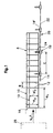
- the rectangular, flat objects 10, in the present case printed products such as newspapers, magazines and the like, are conveyed in a scale flow S in the direction of conveyance F at the conveying speed v 1 .
- the objects always have a specific first dimension A, measured in the conveying direction F; this means that they are always of the same length when viewed in the conveying direction F.
- Their extent at right angles to the conveying direction - ie their width - can be different, as is indicated by means of the second extent A 2 and A 2 ' .
- the scale distance B is always constant. Scale spacing is understood to mean the distance between the front edge 12 of successive objects 10. Since the objects 10, measured in the conveying direction F, always have a certain first dimension A, the distance between the rear edges of the objects also corresponds to the scale distance B.
- the objects 10 are arranged in the scale stream S in such a way that that their running in the conveying direction F are on the right in the conveying direction Side edges 14 are aligned.
- the right side edge the stream of scale is therefore independent of the format of the objects 10 always in a certain lateral position.
- the scale flow S is on a belt conveyor indicated by dashed lines 16 transported and stands with one adjoining the side edge 14 Edge area laterally above the belt conveyor 16.
- the transport clamps 18 are driven to a V in the conveying direction F at the conveying speed 1 conveying member 22 arranged at a constant center distance C one behind the other.
- the transport clamps 18 are designed to hold a certain number - one section - of the objects 10 of the shingled stream S from the side and to hold them for further transport.
- the center distance C of the transport brackets 18 is selected such that each of the objects 10 is only gripped by a single transport clamp 18 - that is to say that the transport clamps 18, viewed in the conveying direction F, the object 10 at the front of a section adjacent to its rear edge and the rearmost object 10 of this section capture adjacent to the front edge 12 thereof.
- the objects 10 are gripped by means of the transport clamp 18, if this is formed with narrow clamping tongues 24 when viewed in the conveying direction F, in an area in which all objects 10 of a section overlap.
- the lateral grasping of these objects 10 by means of the transport clamps 18 enables the formation of the transport clamps 18 with short clamping tongues as seen in the direction perpendicular to the conveying direction F.
- the transport clamps 18 with the clamping tongues in the open position 24 are from the side to the side edge 14 of the objects of Scale stream S brought up and then transferred to the closed position. As soon as the transport clamps 18 are brought into the closed position, the objects 10 are conveyed away from the belt conveyor 16. For further transport can either be carried in a hanging position or in horizontal position outside the movement path 18 'of the transport clamps 18 supported further.
- the further transport of the articles 10 in sections can be carried out independently the format of the objects 10 in the same conveyor 20.
- Longitudinal rotary printing machines produce printed products with a constant first dimension A in the direction of delivery, and lay them out in a regular scale formation.
- the second dimension A 2 , A 2 'of the printed products ie their width, can vary depending on the desired format, for example the newspaper.
- the present invention permits the disposal of such longitudinally dimensioning rotary printing presses without changing the formation with an extremely simple clamp conveyor in the manner of a section conveyor, without the scale formation having to be disturbed in the process.
- the flat objects 10 In the case of transverse rotary printing presses 26 and delivery from storage units, such as, for example, windings, the flat objects 10, the printed products, can have a different length, ie a different second dimension A 2 , when viewed in the delivery direction. In contrast, in this case the width of the objects 10, ie the first dimension A 1, is always unchanged. From a scale formation of this type, a scale flow is now formed by deflecting or rotating the objects, in which the determined first extent A, the objects 10 runs in the conveying direction F, the scale distance S is constant and the one side edge 14 of the objects 10 is aligned with one another and is in a certain lateral position.
- Fig. 2 shows a first embodiment, in which by deflecting the 26 objects from a transverse rotary printing press Such a scale flow from the resulting scale formation S is formed.
- the outlet 28 'of a feed conveyor designed as a belt conveyor 28 it can be the delivery belt of the rotary printing press act - is arranged on one side of a conveyor 30, the runs at right angles to the feed direction Z of the feed conveyor 28.
- the deflector 32 has two conical rollers spaced apart from one another in the conveying direction F. 34, which are driven to rotate about axes 34 ', in the feed direction Z run.
- a transfer device 36 of this type is in CH-A-617 408 and in the corresponding US-A-4,201,377. In terms of Structure and operation of the transfer device 36 is expressly referred to these publications.
- the conveyor 30 corresponds in its structure and mode of operation the belt conveyor 16 according to FIG. 1. Furthermore, as shown in FIG. 1 and described, a conveyor 20 is provided, which is intended the objects conveyed in the scale stream S by means of the conveyor 30 10 to be gripped in sections.
- the conveyor 20 has several downstream of the conveyor 30 Dispensing points 38 - two are shown in FIG. 2 - on. Every delivery point 38 is assigned a further belt conveyor 40, which is a further transfer device 36 ', which are of the same design as the transfer device 36, but depending on the operating case, the deflection members 32 a deflection into a rest position and can be brought back again. In Deflection form the deflection members 32 together with a relevant one Belt conveyor the effective conveyor gap. However, they are off at rest the path of movement of the objects held by the transport clamps 18 10 removed so that this at the relevant delivery point 38th can be funded past to another delivery point.
- the position of the deflection members 32 of the transfer device 36 in the feed direction Z can be adjusted in accordance with the second extent A 2 , A 2 'of the objects 10, such that the side edges 14 of the objects facing the conveyor device 20 in the shingled stream S. always in the same place.
- the operation of the device shown in a highly simplified manner in FIG. 2 is as follows:
- the rotary printing machine 26 places the objects 10 in a scale formation in which the first dimension A, measured at right angles to the direction of delivery, of the objects always has the same specific size.
- the second dimension A 2 , A 2 ' measured in the direction of delivery, but can be different. If objects 10 with the second dimension A 2 are laid out, they are fed in the regular scale formation by means of the feed conveyor 28 in the feed direction Z to the transfer device 36. Together with the conveyor 30, this deflects the objects 10 by 90 ° so that they are conveyed further in the scale direction S in the conveying direction F.
- the conveying speed v 1 of the removal conveyor 30 is matched to the conveying speed v z of the feed conveyor 28 such that the scale distance B in the scale flow S is constant.
- a certain number, in the present case six, of the objects 10 in the stream of scales from the side of the aligned side edge 14 are detected and transported by each transport clamp 18.
- the first delivery point 38 is active and deflects the articles 10 released section by section from the open transport clamp 18 in question to form a scale formation on the belt conveyor 40 in question.
- a belt conveyor adjoins the belt conveyor 40, said belt conveyor releasing the objects 10 of the section in question in the conveying direction F to the relevant section Transfer device 36 'further promoted.
- the deflection members 32 of the transfer device 36 are displaced by the difference between the second extensions A 2 and A 2 ' against the feed direction Z.
- the right-hand side edge 14 of all objects 10, as seen in the conveying direction F is again at the same location. This ensures problem-free section-by-section acceptance of the objects 10 by means of the transport clamps 18.
- the device works the same as described above.
- the design shown in FIG. 3 is very similar to that of FIG. 2, but now the transfer device 36 between the feed conveyor 28 and the conveyor 30 running at right angles to this has an intermediate conveyor 44 arranged at an angle to both conveyors - the angle between The conveying direction Z of the feed conveyor 28 and the conveying direction of the intermediate conveyor 44 is 45 °, but it can also be larger or smaller.
- the intermediate conveyor 44 has a plurality of conveyor belts 46 arranged next to one another, which interact with weight rollers 48.
- the feed conveyor 28, which is designed as a belt conveyor is assigned further weight rollers 48 'at its outlet 28'.
- the transfer device 36 has a stop 50 which is assigned to the travel conveyor 30 and which is designed as a belt conveyor and which can be set as a function of the second dimension A 2 .
- FIG 3 shows objects 10 arranged on the side of the feed conveyor 28 with solid lines in a shingled formation, folded newspapers which, viewed in the feed direction Z, have a second dimension A 2 .
- Objects 10 are shown with dash-dotted lines and have a much shorter second dimension A 2 '.
- the scale spacing of the objects 10 and their first dimension A 1 is always the same. This and the coordinated speeds of all conveyors ensure that the shingle spacing B in shingle stream S has the desired size.
- all objects 10 are transferred into the scale formation S in such a way that their specific first dimension A 1 runs in the conveying direction F.
- each of the transport clamps 18 detects three objects 10 for further transport and each object 10 is held by a single transport clamp 18.
- Possible forms of formation for transfer devices 36 according to FIG. 3 are for example in EP-A-0 310 988, EP-A-0 484 177 and WO 94/13566.
- the objects fall with certain perpendicular to their conveying direction first expansion and different in the direction of conveyance. Expansion, they can also extend around a cross-section of the object surface Axis are rotated. Suitable devices are, for example from CH-A-546 197 and the corresponding US-A-3,809,214 and EP-A-0 901 977.
- the devices can be designed particularly simply if the Objects in a scale formation with constant scale spacing attack. If this is not the case, it can be done in a known manner, for example by adjusting conveyor speeds, the arrangement of the Objects 10 can be achieved in the desired scale distance.
Claims (7)
- Procédé pour le transport d'objets plats, au moins approximativement rectangulaires, se présentant en formation imbriquée, tels que des produits d'imprimerie, comprenant une première extension déterminée (A1) et une deuxième extension variable (A2, A2') s'étendant perpendiculairement à la première, dans lequel les objets (10) sont acheminés dans un flux imbriqué (S) avec une distance imbriquée prédéterminée constante (B), avec une première extension (A1) s'étendant dans la direction d'avance (F), et, vu dans la direction d'avance (F), avec une position latérale déterminée des arêtes (14) des objets (10) s'étendant dans la direction d'avance (F) et orientées les unes vers les autres, d'un côté prédéterminé du flux imbriqué (S), et dans lequel un nombre déterminé respectif, d'au moins deux objets successifs (10) du flux imbriqué (S) est alors saisi par exclusivement une pince de transport (18) du côté du flux imbriqué (S) avec des arêtes (14) orientées les unes vers les autres en vue du transport ultérieur du flux imbriqué (S).
- Procédé selon la revendication 1 pour le transport d'objets (10), qui se présentent avec une première extension (A1) déterminée s'étendant perpendiculairement à leur direction d'avance (Z), caractérisé en ce que les objets (10) sont transférés avant leur saisie par la pince de transport (18) dans le flux imbriqué (S).
- Dispositif pour le transport d'objets plats, au moins approximativement rectangulaires, se présentant en formation imbriquée, tels que des produits d'imprimerie, comprenant une première extension déterminée (A1) et une deuxième extension variable (A2, A2') s'étendant perpendiculairement à la première, avec un convoyeur (16, 30), qui est prévu pour acheminer les objets (10) dans un flux imbriqué (S) avec une distance imbriquée (B) au moins approximativement constante, avec une première extension (A1) s'étendant dans la direction d'avance (F), et, vu dans la direction d'avance (F), avec une position latérale déterminée par rapport au convoyeur (16, 30) des arêtes (14) des objets (10) s'étendant dans la direction d'avance (F) et orientées les unes vers les autres, d'un côté du flux imbriqué (S), et avec un dispositif d'avance (20) monté derrière le convoyeur (16, 30), avec des pinces de transport (18) commandables individuellement, disposées les unes derrière les autres à une distance (C) dans la direction d'avance (F), la voie de déplacement (18') des pinces de transport (18), vue dans la direction d'avance (F) passant devant chaque côté déterminé du convoyeur (16, 30) sur lequel sont orientées les unes vers les autres les arêtes (14) des objets (10), et le convoyeur (16, 30) et le dispositif d'avance (20) étant adaptés l'un à l'autre de telle sorte qu'une pince de transport (18) individuelle saisisse latéralement à chaque fois un nombre déterminé, d'au moins deux objets (10) en vue d'un transport ultérieur du flux imbriqué (S).
- Dispositif selon la revendication 3, caractérisé en ce que les pinces de transport (18) sont disposées les unes derrière les autres à une distance fixe (C) sur un organe d'avance (22) entraíné en rotation dans la direction d'avance (F), la distance (C) étant au moins aussi grande que la première dimension déterminée (A1) des objets (10).
- Dispositif selon la revendication 3 ou 4 pour le transport d'objets (10) se présentant avec une première extension (A1) déterminée s'étendant perpendiculairement à leur direction d'avance (F), caractérisé par un dispositif d'avance (28), qui est prévu pour acheminer les objets (10) dans la formation imbriquée avec une première extension (A1) s'étendant perpendiculairement à la direction d'avance (F), et un dispositif de transfert (36) disposé entre le dispositif d'avance (28) et le convoyeur (16, 30) monté derrière celui-ci, lequel est prévu pour transférer les objets (10) acheminés au moyen du dispositif d'avance (28) dans le flux imbriqué (S) transportable ultérieurement au moyen du convoyeur (16, 30).
- Dispositif selon la revendication 5, caractérisé en ce que le dispositif d'avance (28) présente une sortie (28') disposée d'un côté du convoyeur (30) s'étendant à angle droit par rapport à la direction d'avance (Z) du dispositif d'avance (28), et le dispositif de transfert (36) présente au moins un organe de déviation (32) monté à rotation à distance de la sortie (28') du dispositif d'avance (28) au-dessus du convoyeur (30) et associé à celui-ci, qui forme avec le convoyeur (30) une fente d'avance se rétrécissant dans la direction d'avance (Z) du dispositif d'avance (28) et agissant dans le même sens que la direction d'avance (F) du convoyeur (30).
- Dispositif selon la revendication 5, caractérisé en ce que le dispositif de transfert (36) présente, entre le dispositif d'avance (28) et le convoyeur (30) s'étendant perpendiculairement à la direction d'avance (Z) du dispositif d'avance (28), un convoyeur intermédiaire (44) qui s'étend suivant un angle par rapport aux directions d'avance (Z, F) du dispositif d'avance (28) et du convoyeur (30), les objets (10) conservant une position parallèle les uns aux autres.
Applications Claiming Priority (2)
| Application Number | Priority Date | Filing Date | Title |
|---|---|---|---|
| CH101499 | 1999-05-31 | ||
| CH101499 | 1999-05-31 |
Publications (2)
| Publication Number | Publication Date |
|---|---|
| EP1057762A1 EP1057762A1 (fr) | 2000-12-06 |
| EP1057762B1 true EP1057762B1 (fr) | 2004-02-18 |
Family
ID=4200450
Family Applications (1)
| Application Number | Title | Priority Date | Filing Date |
|---|---|---|---|
| EP00108895A Expired - Lifetime EP1057762B1 (fr) | 1999-05-31 | 2000-04-27 | Procédé et dispositif de transport d'objets arrivant en formation imbriquée |
Country Status (8)
| Country | Link |
|---|---|
| US (1) | US6406014B1 (fr) |
| EP (1) | EP1057762B1 (fr) |
| JP (1) | JP2001010757A (fr) |
| AT (1) | ATE259751T1 (fr) |
| AU (1) | AU768435B2 (fr) |
| CA (1) | CA2309267A1 (fr) |
| DE (1) | DE50005297D1 (fr) |
| DK (1) | DK1057762T3 (fr) |
Families Citing this family (13)
| Publication number | Priority date | Publication date | Assignee | Title |
|---|---|---|---|---|
| ATE273908T1 (de) * | 2001-02-21 | 2004-09-15 | Ferag Ag | Vorrichtung zur übergabe von seriell zugeführten, flachen gegenständen an eine wegförderung |
| DE50204308D1 (de) | 2001-07-18 | 2006-02-02 | Ferag Ag | Verfahren und Vorrichtung zur Wandlung eines Förderstromes von flachen Gegenständen |
| EP1321410B8 (fr) * | 2001-12-21 | 2007-03-14 | Ferag AG | Méthode et dispositif pour transporter des produits plats |
| US6730870B1 (en) * | 2002-09-16 | 2004-05-04 | Todd C. Werner | Flat bed sorter |
| DE102005035333A1 (de) * | 2005-07-28 | 2007-02-01 | Kolbus Gmbh & Co. Kg | Verfahren und Vorrichtung zum Zusammentragen von Druckbogen |
| ITBO20060025A1 (it) * | 2006-01-17 | 2007-07-18 | Cmc Spa | Apparato convogliatore per il cambio della direzione di avanzamneto di articoli in foglio |
| EP2055660B1 (fr) * | 2007-11-01 | 2010-06-09 | Ferag AG | Dispositif de retournement cadencé d'objets plats |
| US8727099B2 (en) | 2010-05-24 | 2014-05-20 | Usnr/Kockums Cancar Company | Tapered roll feed |
| US8794423B2 (en) | 2012-11-21 | 2014-08-05 | Usnr, Llc | Systems, methods and apparatuses for changing the direction/speed of a workpiece |
| WO2014165444A1 (fr) * | 2013-03-31 | 2014-10-09 | Intelligrated Headquarters, Llc | Système de transport à retourneur de caisses |
| CN104709743B (zh) * | 2013-12-16 | 2018-02-23 | 上海旭恒精工机械制造有限公司 | 片状物传输系统 |
| USD914318S1 (en) | 2019-07-25 | 2021-03-23 | Retail Design Services, LLC | Frame for a shopping cart |
| USD914317S1 (en) | 2019-02-13 | 2021-03-23 | Retail Design Services, LLC | Shopping cart |
Family Cites Families (12)
| Publication number | Priority date | Publication date | Assignee | Title |
|---|---|---|---|---|
| CH546197A (de) | 1971-09-14 | 1974-02-28 | Fehr & Reist Ag | Wendefoerderer fuer flaechengebilde, insbesondere druckprodukte. |
| CH617408A5 (fr) | 1977-05-27 | 1980-05-30 | Ferag Ag | |
| FI69814C (fi) * | 1981-03-24 | 1986-05-26 | Will E C H Gmbh & Co | Anordning foer aendring av transportriktningen hos enskilda foremaol |
| DE3361987D1 (en) * | 1982-06-02 | 1986-03-13 | Ferag Ag | Device for transporting continuously supplied flat paper products |
| DE3733906C2 (de) | 1987-10-07 | 2000-12-14 | Gaemmerler Hagen | Umlenkvorrichtung für einen Produktstrom |
| DE58901208D1 (de) * | 1988-03-03 | 1992-05-27 | Ferag Ag | Verfahren und vorrichtung zum wegfoerdern von druckereiprodukten, die in einer schuppenformation zugefuehrt werden. |
| CA2054515C (fr) | 1990-11-02 | 2002-03-19 | Shahzad H. Malick | Appareil servant a modifier le sens de deplacement d'articles plats et methode connexe |
| CH683094A5 (de) * | 1991-06-27 | 1994-01-14 | Ferag Ag | Verfahren und Vorrichtung zum Wegfördern von in einem Schuppenstrom zugeführten flächigen Erzeugnissen, insbesondere Druckprodukten. |
| EP0625121A1 (fr) | 1992-12-04 | 1994-11-23 | Grapha-Holding Ag | Installation pour le transfert d'un flux de nappes constitue de produits imprimes |
| DE19500560A1 (de) * | 1995-01-11 | 1996-07-18 | Kolbus Gmbh & Co Kg | Verfahren zum Transportieren von Druckprodukten zwischen weiterverarbeitenden Buchbindemaschinen und Vorrichtung zur Durchführung des Verfahrens |
| DE59806032D1 (de) | 1997-09-10 | 2002-11-28 | Ferag Ag | Einrichtung zum Drehen von in einer Schuppenformation anfallenden Erzeugnissen |
| AU752572C (en) * | 1998-04-28 | 2003-07-24 | Ferag Ag | Method and device for further conveyance of flat objects arriving in a lamellar flow |
-
2000
- 2000-04-27 AT AT00108895T patent/ATE259751T1/de not_active IP Right Cessation
- 2000-04-27 DE DE50005297T patent/DE50005297D1/de not_active Expired - Lifetime
- 2000-04-27 DK DK00108895T patent/DK1057762T3/da active
- 2000-04-27 EP EP00108895A patent/EP1057762B1/fr not_active Expired - Lifetime
- 2000-05-18 AU AU35382/00A patent/AU768435B2/en not_active Ceased
- 2000-05-23 JP JP2000155958A patent/JP2001010757A/ja active Pending
- 2000-05-24 CA CA002309267A patent/CA2309267A1/fr not_active Abandoned
- 2000-05-31 US US09/584,595 patent/US6406014B1/en not_active Expired - Fee Related
Also Published As
| Publication number | Publication date |
|---|---|
| CA2309267A1 (fr) | 2000-11-30 |
| DK1057762T3 (da) | 2004-03-08 |
| JP2001010757A (ja) | 2001-01-16 |
| AU3538200A (en) | 2000-12-07 |
| DE50005297D1 (de) | 2004-03-25 |
| US6406014B1 (en) | 2002-06-18 |
| ATE259751T1 (de) | 2004-03-15 |
| EP1057762A1 (fr) | 2000-12-06 |
| AU768435B2 (en) | 2003-12-11 |
Similar Documents
| Publication | Publication Date | Title |
|---|---|---|
| EP0827931B1 (fr) | Dispositif et méthode pour le guidage dynamique d'objets plats | |
| EP1057762B1 (fr) | Procédé et dispositif de transport d'objets arrivant en formation imbriquée | |
| WO2010051651A2 (fr) | Dispositif et procédé pour assembler des objets plats | |
| EP1712495A2 (fr) | Dispositif de transfert de produits imprimés délivrés de manière continue d'une position couchée à une position verticale ou inversement | |
| DE3603285C2 (de) | Zusammentragmaschine | |
| DE3306815C2 (de) | Vorrichtung zum transportieren von in einer schuppenformation anfallenden flaechigen erzeugnissen, insbesondere druckprodukten | |
| WO1995009796A1 (fr) | Procede et dispositif permettant de former et de deplacer des piles de feuilles imprimees | |
| EP0854105B1 (fr) | Méthode et dispositif pour traiter des produits imprimes plats, comme des journaux, des magazines, et des parties de cela | |
| EP0259650A2 (fr) | Méthode et dispositif pour régulariser la distance séparant deux articles successifs d'un courant d'articles en écailles de poisson, notamment d'imprimés | |
| EP1991484B1 (fr) | Dispositif et procede pour former des piles de produits plats | |
| EP0625122B1 (fr) | Installation pour le transport et la separation de produits d'impression plies | |
| DE102006005156A1 (de) | Vorrichtung zum Ablegen von einzeln aufeinanderfolgend zugeführten Druckprodukten in einer geschuppt übereinanderliegenden Formation | |
| EP0478911B1 (fr) | Dispositif de transfert sélectif d'articles se chevauchant d'un premier chemin de transport à un deuxième chemin de transport | |
| DE4330427A1 (de) | Verfahren und Vorrichtung zur Bildung von Stapeln von Warenstücken, insbesondere Keksen | |
| DE2917250A1 (de) | Vorrichtung zur taktung der ueberlappungslaenge von in einem im wesentlichen gleichmaessigen schuppenstrom gefoerderten, flaechenhaften produkten | |
| EP1350750B1 (fr) | Méthode et dispositif pour former des piles d'objets plats arrivant en continu | |
| DE19643395A1 (de) | Verfahren und Vorrichtung zum Zusammenbringen von Druckereierzeugnissen | |
| EP1273542B1 (fr) | Dispositif pour transporter des produits imprimés empilés les uns sur les autres sur un support | |
| EP1075445B1 (fr) | Procede et dispositif pour poursuivre l'acheminement d'objets plats arrivant dans un courant lamellaire | |
| EP0806391B1 (fr) | Dispositif pour l'alimentation de produits imprimés vers un autre poste de travail | |
| CH663398A5 (de) | Falzapparat fuer eine rollenrotationsdruckmaschine. | |
| EP1607356B1 (fr) | Dispositif d'alignement de feuilles empilées | |
| DE19743020C2 (de) | Vorrichtung sowie Verfahren zur Vereinzelung von Druckprodukten | |
| DE4314644A1 (de) | Vorrichtung zum Ablegen flacher Gegenstände in Hochkantlage auf einem Transportband oder dergleichen | |
| CH627997A5 (en) | Device for forming a continuous branch stream from a main stream of continuously occurring flat products, in particular printed products |
Legal Events
| Date | Code | Title | Description |
|---|---|---|---|
| PUAI | Public reference made under article 153(3) epc to a published international application that has entered the european phase |
Free format text: ORIGINAL CODE: 0009012 |
|
| AK | Designated contracting states |
Kind code of ref document: A1 Designated state(s): AT BE CH CY DE DK ES FI FR GB GR IE IT LI LU MC NL PT SE |
|
| AX | Request for extension of the european patent |
Free format text: AL;LT;LV;MK;RO;SI |
|
| 17P | Request for examination filed |
Effective date: 20010601 |
|
| AKX | Designation fees paid |
Free format text: AT BE CH CY DE DK ES FI FR GB GR IE IT LI LU MC NL PT SE |
|
| 17Q | First examination report despatched |
Effective date: 20021105 |
|
| GRAP | Despatch of communication of intention to grant a patent |
Free format text: ORIGINAL CODE: EPIDOSNIGR1 |
|
| GRAS | Grant fee paid |
Free format text: ORIGINAL CODE: EPIDOSNIGR3 |
|
| GRAA | (expected) grant |
Free format text: ORIGINAL CODE: 0009210 |
|
| AK | Designated contracting states |
Kind code of ref document: B1 Designated state(s): AT BE CH CY DE DK ES FI FR GB GR IE IT LI LU MC NL PT SE |
|
| PG25 | Lapsed in a contracting state [announced via postgrant information from national office to epo] |
Ref country code: FR Free format text: LAPSE BECAUSE OF FAILURE TO SUBMIT A TRANSLATION OF THE DESCRIPTION OR TO PAY THE FEE WITHIN THE PRESCRIBED TIME-LIMIT Effective date: 20040218 Ref country code: CY Free format text: LAPSE BECAUSE OF FAILURE TO SUBMIT A TRANSLATION OF THE DESCRIPTION OR TO PAY THE FEE WITHIN THE PRESCRIBED TIME-LIMIT Effective date: 20040218 Ref country code: FI Free format text: LAPSE BECAUSE OF FAILURE TO SUBMIT A TRANSLATION OF THE DESCRIPTION OR TO PAY THE FEE WITHIN THE PRESCRIBED TIME-LIMIT Effective date: 20040218 Ref country code: NL Free format text: LAPSE BECAUSE OF FAILURE TO SUBMIT A TRANSLATION OF THE DESCRIPTION OR TO PAY THE FEE WITHIN THE PRESCRIBED TIME-LIMIT Effective date: 20040218 Ref country code: IE Free format text: LAPSE BECAUSE OF FAILURE TO SUBMIT A TRANSLATION OF THE DESCRIPTION OR TO PAY THE FEE WITHIN THE PRESCRIBED TIME-LIMIT Effective date: 20040218 |
|
| REG | Reference to a national code |
Ref country code: GB Ref legal event code: FG4D Free format text: NOT ENGLISH |
|
| REG | Reference to a national code |
Ref country code: CH Ref legal event code: NV Representative=s name: PATENTANWAELTE SCHAAD, BALASS, MENZL & PARTNER AG Ref country code: CH Ref legal event code: EP |
|
| REG | Reference to a national code |
Ref country code: DK Ref legal event code: T3 |
|
| GBT | Gb: translation of ep patent filed (gb section 77(6)(a)/1977) |
Effective date: 20040218 |
|
| REG | Reference to a national code |
Ref country code: IE Ref legal event code: FG4D Free format text: GERMAN |
|
| REF | Corresponds to: |
Ref document number: 50005297 Country of ref document: DE Date of ref document: 20040325 Kind code of ref document: P |
|
| PGFP | Annual fee paid to national office [announced via postgrant information from national office to epo] |
Ref country code: GB Payment date: 20040331 Year of fee payment: 5 |
|
| PGFP | Annual fee paid to national office [announced via postgrant information from national office to epo] |
Ref country code: SE Payment date: 20040402 Year of fee payment: 5 |
|
| PG25 | Lapsed in a contracting state [announced via postgrant information from national office to epo] |
Ref country code: AT Free format text: LAPSE BECAUSE OF NON-PAYMENT OF DUE FEES Effective date: 20040427 Ref country code: LU Free format text: LAPSE BECAUSE OF NON-PAYMENT OF DUE FEES Effective date: 20040427 |
|
| REG | Reference to a national code |
Ref country code: SE Ref legal event code: TRGR |
|
| PG25 | Lapsed in a contracting state [announced via postgrant information from national office to epo] |
Ref country code: MC Free format text: LAPSE BECAUSE OF NON-PAYMENT OF DUE FEES Effective date: 20040430 Ref country code: BE Free format text: LAPSE BECAUSE OF NON-PAYMENT OF DUE FEES Effective date: 20040430 |
|
| PG25 | Lapsed in a contracting state [announced via postgrant information from national office to epo] |
Ref country code: GR Free format text: LAPSE BECAUSE OF FAILURE TO SUBMIT A TRANSLATION OF THE DESCRIPTION OR TO PAY THE FEE WITHIN THE PRESCRIBED TIME-LIMIT Effective date: 20040518 |
|
| PG25 | Lapsed in a contracting state [announced via postgrant information from national office to epo] |
Ref country code: ES Free format text: LAPSE BECAUSE OF FAILURE TO SUBMIT A TRANSLATION OF THE DESCRIPTION OR TO PAY THE FEE WITHIN THE PRESCRIBED TIME-LIMIT Effective date: 20040529 |
|
| NLV1 | Nl: lapsed or annulled due to failure to fulfill the requirements of art. 29p and 29m of the patents act | ||
| REG | Reference to a national code |
Ref country code: IE Ref legal event code: FD4D |
|
| BERE | Be: lapsed |
Owner name: FERAG AG Effective date: 20040430 |
|
| PLBE | No opposition filed within time limit |
Free format text: ORIGINAL CODE: 0009261 |
|
| STAA | Information on the status of an ep patent application or granted ep patent |
Free format text: STATUS: NO OPPOSITION FILED WITHIN TIME LIMIT |
|
| EN | Fr: translation not filed | ||
| 26N | No opposition filed |
Effective date: 20041119 |
|
| REG | Reference to a national code |
Ref country code: CH Ref legal event code: PFA Owner name: FERAG AG Free format text: FERAG AG#ZUERICHSTRASSE 74#8340 HINWIL (CH) -TRANSFER TO- FERAG AG#PATENTABTEILUNG Z. H. MARKUS FELIX ZUERICHSTRASSE 74#8340 HINWIL (CH) |
|
| PG25 | Lapsed in a contracting state [announced via postgrant information from national office to epo] |
Ref country code: IT Free format text: LAPSE BECAUSE OF NON-PAYMENT OF DUE FEES Effective date: 20050427 Ref country code: GB Free format text: LAPSE BECAUSE OF NON-PAYMENT OF DUE FEES Effective date: 20050427 |
|
| PG25 | Lapsed in a contracting state [announced via postgrant information from national office to epo] |
Ref country code: SE Free format text: LAPSE BECAUSE OF NON-PAYMENT OF DUE FEES Effective date: 20050428 |
|
| EUG | Se: european patent has lapsed | ||
| GBPC | Gb: european patent ceased through non-payment of renewal fee |
Effective date: 20050427 |
|
| PG25 | Lapsed in a contracting state [announced via postgrant information from national office to epo] |
Ref country code: PT Free format text: LAPSE BECAUSE OF NON-PAYMENT OF DUE FEES Effective date: 20040718 |
|
| PGFP | Annual fee paid to national office [announced via postgrant information from national office to epo] |
Ref country code: DE Payment date: 20110421 Year of fee payment: 12 Ref country code: CH Payment date: 20110420 Year of fee payment: 12 |
|
| PGFP | Annual fee paid to national office [announced via postgrant information from national office to epo] |
Ref country code: DK Payment date: 20110418 Year of fee payment: 12 |
|
| REG | Reference to a national code |
Ref country code: DK Ref legal event code: EBP |
|
| REG | Reference to a national code |
Ref country code: CH Ref legal event code: PL |
|
| PG25 | Lapsed in a contracting state [announced via postgrant information from national office to epo] |
Ref country code: CH Free format text: LAPSE BECAUSE OF NON-PAYMENT OF DUE FEES Effective date: 20120430 Ref country code: LI Free format text: LAPSE BECAUSE OF NON-PAYMENT OF DUE FEES Effective date: 20120430 |
|
| REG | Reference to a national code |
Ref country code: DE Ref legal event code: R119 Ref document number: 50005297 Country of ref document: DE Effective date: 20121101 |
|
| PG25 | Lapsed in a contracting state [announced via postgrant information from national office to epo] |
Ref country code: DK Free format text: LAPSE BECAUSE OF NON-PAYMENT OF DUE FEES Effective date: 20120430 |
|
| PG25 | Lapsed in a contracting state [announced via postgrant information from national office to epo] |
Ref country code: DE Free format text: LAPSE BECAUSE OF NON-PAYMENT OF DUE FEES Effective date: 20121101 |