EP1057582A1 - Machines d'usinage, en particulier machine foreuse et/ou fraiseuse - Google Patents
Machines d'usinage, en particulier machine foreuse et/ou fraiseuse Download PDFInfo
- Publication number
- EP1057582A1 EP1057582A1 EP99109993A EP99109993A EP1057582A1 EP 1057582 A1 EP1057582 A1 EP 1057582A1 EP 99109993 A EP99109993 A EP 99109993A EP 99109993 A EP99109993 A EP 99109993A EP 1057582 A1 EP1057582 A1 EP 1057582A1
- Authority
- EP
- European Patent Office
- Prior art keywords
- processing
- area
- machine according
- guide rails
- machining
- Prior art date
- Legal status (The legal status is an assumption and is not a legal conclusion. Google has not performed a legal analysis and makes no representation as to the accuracy of the status listed.)
- Granted
Links
Images

Classifications
-
- B—PERFORMING OPERATIONS; TRANSPORTING
- B23—MACHINE TOOLS; METAL-WORKING NOT OTHERWISE PROVIDED FOR
- B23Q—DETAILS, COMPONENTS, OR ACCESSORIES FOR MACHINE TOOLS, e.g. ARRANGEMENTS FOR COPYING OR CONTROLLING; MACHINE TOOLS IN GENERAL CHARACTERISED BY THE CONSTRUCTION OF PARTICULAR DETAILS OR COMPONENTS; COMBINATIONS OR ASSOCIATIONS OF METAL-WORKING MACHINES, NOT DIRECTED TO A PARTICULAR RESULT
- B23Q11/00—Accessories fitted to machine tools for keeping tools or parts of the machine in good working condition or for cooling work; Safety devices specially combined with or arranged in, or specially adapted for use in connection with, machine tools
- B23Q11/0042—Devices for removing chips
- B23Q11/0053—Devices for removing chips using the gravity force
-
- B—PERFORMING OPERATIONS; TRANSPORTING
- B23—MACHINE TOOLS; METAL-WORKING NOT OTHERWISE PROVIDED FOR
- B23Q—DETAILS, COMPONENTS, OR ACCESSORIES FOR MACHINE TOOLS, e.g. ARRANGEMENTS FOR COPYING OR CONTROLLING; MACHINE TOOLS IN GENERAL CHARACTERISED BY THE CONSTRUCTION OF PARTICULAR DETAILS OR COMPONENTS; COMBINATIONS OR ASSOCIATIONS OF METAL-WORKING MACHINES, NOT DIRECTED TO A PARTICULAR RESULT
- B23Q1/00—Members which are comprised in the general build-up of a form of machine, particularly relatively large fixed members
- B23Q1/01—Frames, beds, pillars or like members; Arrangement of ways
- B23Q1/015—Frames, beds, pillars
-
- B—PERFORMING OPERATIONS; TRANSPORTING
- B23—MACHINE TOOLS; METAL-WORKING NOT OTHERWISE PROVIDED FOR
- B23Q—DETAILS, COMPONENTS, OR ACCESSORIES FOR MACHINE TOOLS, e.g. ARRANGEMENTS FOR COPYING OR CONTROLLING; MACHINE TOOLS IN GENERAL CHARACTERISED BY THE CONSTRUCTION OF PARTICULAR DETAILS OR COMPONENTS; COMBINATIONS OR ASSOCIATIONS OF METAL-WORKING MACHINES, NOT DIRECTED TO A PARTICULAR RESULT
- B23Q1/00—Members which are comprised in the general build-up of a form of machine, particularly relatively large fixed members
- B23Q1/01—Frames, beds, pillars or like members; Arrangement of ways
- B23Q1/017—Arrangements of ways
-
- B—PERFORMING OPERATIONS; TRANSPORTING
- B23—MACHINE TOOLS; METAL-WORKING NOT OTHERWISE PROVIDED FOR
- B23Q—DETAILS, COMPONENTS, OR ACCESSORIES FOR MACHINE TOOLS, e.g. ARRANGEMENTS FOR COPYING OR CONTROLLING; MACHINE TOOLS IN GENERAL CHARACTERISED BY THE CONSTRUCTION OF PARTICULAR DETAILS OR COMPONENTS; COMBINATIONS OR ASSOCIATIONS OF METAL-WORKING MACHINES, NOT DIRECTED TO A PARTICULAR RESULT
- B23Q1/00—Members which are comprised in the general build-up of a form of machine, particularly relatively large fixed members
- B23Q1/25—Movable or adjustable work or tool supports
- B23Q1/44—Movable or adjustable work or tool supports using particular mechanisms
- B23Q1/56—Movable or adjustable work or tool supports using particular mechanisms with sliding pairs only, the sliding pairs being the first two elements of the mechanism
- B23Q1/60—Movable or adjustable work or tool supports using particular mechanisms with sliding pairs only, the sliding pairs being the first two elements of the mechanism two sliding pairs only, the sliding pairs being the first two elements of the mechanism
- B23Q1/62—Movable or adjustable work or tool supports using particular mechanisms with sliding pairs only, the sliding pairs being the first two elements of the mechanism two sliding pairs only, the sliding pairs being the first two elements of the mechanism with perpendicular axes, e.g. cross-slides
- B23Q1/621—Movable or adjustable work or tool supports using particular mechanisms with sliding pairs only, the sliding pairs being the first two elements of the mechanism two sliding pairs only, the sliding pairs being the first two elements of the mechanism with perpendicular axes, e.g. cross-slides a single sliding pair followed perpendicularly by a single sliding pair
- B23Q1/623—Movable or adjustable work or tool supports using particular mechanisms with sliding pairs only, the sliding pairs being the first two elements of the mechanism two sliding pairs only, the sliding pairs being the first two elements of the mechanism with perpendicular axes, e.g. cross-slides a single sliding pair followed perpendicularly by a single sliding pair followed perpendicularly by a single rotating pair
-
- Y—GENERAL TAGGING OF NEW TECHNOLOGICAL DEVELOPMENTS; GENERAL TAGGING OF CROSS-SECTIONAL TECHNOLOGIES SPANNING OVER SEVERAL SECTIONS OF THE IPC; TECHNICAL SUBJECTS COVERED BY FORMER USPC CROSS-REFERENCE ART COLLECTIONS [XRACs] AND DIGESTS
- Y10—TECHNICAL SUBJECTS COVERED BY FORMER USPC
- Y10T—TECHNICAL SUBJECTS COVERED BY FORMER US CLASSIFICATION
- Y10T29/00—Metal working
- Y10T29/50—Convertible metal working machine
-
- Y—GENERAL TAGGING OF NEW TECHNOLOGICAL DEVELOPMENTS; GENERAL TAGGING OF CROSS-SECTIONAL TECHNOLOGIES SPANNING OVER SEVERAL SECTIONS OF THE IPC; TECHNICAL SUBJECTS COVERED BY FORMER USPC CROSS-REFERENCE ART COLLECTIONS [XRACs] AND DIGESTS
- Y10—TECHNICAL SUBJECTS COVERED BY FORMER USPC
- Y10T—TECHNICAL SUBJECTS COVERED BY FORMER US CLASSIFICATION
- Y10T408/00—Cutting by use of rotating axially moving tool
- Y10T408/91—Machine frame
-
- Y—GENERAL TAGGING OF NEW TECHNOLOGICAL DEVELOPMENTS; GENERAL TAGGING OF CROSS-SECTIONAL TECHNOLOGIES SPANNING OVER SEVERAL SECTIONS OF THE IPC; TECHNICAL SUBJECTS COVERED BY FORMER USPC CROSS-REFERENCE ART COLLECTIONS [XRACs] AND DIGESTS
- Y10—TECHNICAL SUBJECTS COVERED BY FORMER USPC
- Y10T—TECHNICAL SUBJECTS COVERED BY FORMER US CLASSIFICATION
- Y10T409/00—Gear cutting, milling, or planing
- Y10T409/30—Milling
- Y10T409/30392—Milling with means to protect operative or machine [e.g., guard, safety device, etc.]
-
- Y—GENERAL TAGGING OF NEW TECHNOLOGICAL DEVELOPMENTS; GENERAL TAGGING OF CROSS-SECTIONAL TECHNOLOGIES SPANNING OVER SEVERAL SECTIONS OF THE IPC; TECHNICAL SUBJECTS COVERED BY FORMER USPC CROSS-REFERENCE ART COLLECTIONS [XRACs] AND DIGESTS
- Y10—TECHNICAL SUBJECTS COVERED BY FORMER USPC
- Y10T—TECHNICAL SUBJECTS COVERED BY FORMER US CLASSIFICATION
- Y10T409/00—Gear cutting, milling, or planing
- Y10T409/30—Milling
- Y10T409/306664—Milling including means to infeed rotary cutter toward work
- Y10T409/307728—Milling including means to infeed rotary cutter toward work including gantry-type cutter-carrier
-
- Y—GENERAL TAGGING OF NEW TECHNOLOGICAL DEVELOPMENTS; GENERAL TAGGING OF CROSS-SECTIONAL TECHNOLOGIES SPANNING OVER SEVERAL SECTIONS OF THE IPC; TECHNICAL SUBJECTS COVERED BY FORMER USPC CROSS-REFERENCE ART COLLECTIONS [XRACs] AND DIGESTS
- Y10—TECHNICAL SUBJECTS COVERED BY FORMER USPC
- Y10T—TECHNICAL SUBJECTS COVERED BY FORMER US CLASSIFICATION
- Y10T409/00—Gear cutting, milling, or planing
- Y10T409/30—Milling
- Y10T409/30784—Milling including means to adustably position cutter
- Y10T409/307952—Linear adjustment
- Y10T409/308288—Linear adjustment including gantry-type cutter-carrier
-
- Y—GENERAL TAGGING OF NEW TECHNOLOGICAL DEVELOPMENTS; GENERAL TAGGING OF CROSS-SECTIONAL TECHNOLOGIES SPANNING OVER SEVERAL SECTIONS OF THE IPC; TECHNICAL SUBJECTS COVERED BY FORMER USPC CROSS-REFERENCE ART COLLECTIONS [XRACs] AND DIGESTS
- Y10—TECHNICAL SUBJECTS COVERED BY FORMER USPC
- Y10T—TECHNICAL SUBJECTS COVERED BY FORMER US CLASSIFICATION
- Y10T483/00—Tool changing
- Y10T483/11—Tool changing with safety means
- Y10T483/115—Guard
-
- Y—GENERAL TAGGING OF NEW TECHNOLOGICAL DEVELOPMENTS; GENERAL TAGGING OF CROSS-SECTIONAL TECHNOLOGIES SPANNING OVER SEVERAL SECTIONS OF THE IPC; TECHNICAL SUBJECTS COVERED BY FORMER USPC CROSS-REFERENCE ART COLLECTIONS [XRACs] AND DIGESTS
- Y10—TECHNICAL SUBJECTS COVERED BY FORMER USPC
- Y10T—TECHNICAL SUBJECTS COVERED BY FORMER US CLASSIFICATION
- Y10T483/00—Tool changing
- Y10T483/17—Tool changing including machine tool or component
- Y10T483/1733—Rotary spindle machine tool [e.g., milling machine, boring, machine, grinding machine, etc.]
- Y10T483/179—Direct tool exchange between spindle and matrix
- Y10T483/1793—Spindle comprises tool changer
Definitions
- the invention relates to a processing machine, in particular Drilling and / or milling machine, with a machine stand, on which a motorized one guided on guide rails driven first carriage in a first horizontal Direction of movement is movable, a motor driven second carriage in a second horizontal direction of movement perpendicular to the first direction of movement is guided on the first sled with a arranged on the second carriage, a drive device for at least one rotating tool Processing head and with a processing table in one Machining area below the machining head, the Motor-guided sliding on vertical guide rails is for performing vertical machining movements when machining workpieces using the machining head.
- Such a processing machine known from DE 14 77 580 A. has a machine stand that consists of two connected to each other by four vertical bars Plates exists.
- the bars serve as vertical Guide rails for a machining table while the upper plate serves as a slide guide.
- the editing area is open on all four sides, so that one Defined discharge of those arising during processing Material removal as well as coolants and lubricants are not is possible.
- the well-known rod construction not suitable for precise machining operations.
- An object of the present invention is a processing machine of the type mentioned to improve so that a narrower design and a better accessibility and arrangement of a tool magazine can be achieved.
- This object is achieved in that the Machining area through two side walls of the machine stand is at least partially limited laterally run parallel to the first horizontal direction of movement, and that the vertical guide rails for the machining table are arranged on one of the side walls.
- the vertical guide rails for the processing table By arranging the vertical guide rails for the processing table on one of the two side walls is the wall of the die facing the machining area stand area connecting both side walls freely for constructive measures so that a simple Access to a tool magazine arranged behind it can be.
- Another advantage is that the machining area is below the machining table tapered towards a narrow discharge area that runs parallel to that side wall, on which the vertical guide rails are arranged are. This allows you to run parallel to these two Side walls or between these discharge channel for material removal as well as cooling and Lubricant that is to the rear of the machine runs. This enables a very narrow construction and a series of such narrow processing machines.
- Two horizontal guide rails for the first slide run at least partially on the side walls and parallel to these, creating a mechanically very stable and high-precision slide guide for the first slide is achieved.
- One of these horizontal guide rails is more advantageous Formed longer than the other, and the first carriage has a 3-point guide, two spaced apart guide elements on the longer one and a guide element on the shorter guide rail are led. This leaves the area between the both guide rails free, so that one arranged there Tool magazine is easily accessible.
- a structurally particularly favorable arrangement results thereby in that the machine stand in extension the side wall carrying the longer guide rail has an asymmetrical rear extension that the rear area of this guide rail carries.
- It preferably carries the side of the center line between the two guide rails for the first Asymmetrical extension of the machine stand arranged on a slide also a spindle drive for the first Carriage, so that also in this regard the tool magazine containing central area of the machine stand is easily accessible at the top.
- the vertical guide rails for the machining table are preferably on the longer guide rail for arranged the first carriage carrying side wall, which in addition to increasing stability and torsional rigidity contributes.
- the machining area below the machining table advantageously has an inclined surface that is from the one not provided with the vertical guide rail Side wall from obliquely down to the opposite Side wall extends, this inclined surface as a feed surface for those arising during processing Material removal as well as coolants and lubricants a discharge duct arranged below the processing area is formed, which is preferably between the side walls to the rear end area of the Machine stand extends.
- the material removal or resulting chips can ideally be led away at the rear, so that the two side walls remain free, creating a close succession of such Processing machines is possible.
- the back running drainage channel also contributes to a very narrow construction of the machine.
- the processing table has below a processing plate one to that of on one side by the Inclined surface limited lower part of the machining area adapted shape so that despite sloping surface far lowered machining positions and a space-saving Arrangement can be realized.
- a stationary drive motor for the machining table engages at least in its lowest position a cavity of this machining table, the Drive motor preferably a lifting spindle for the machining table drives. This also contributes to a compact and space-saving arrangement.
- the processing area is advantageous after a third, facing away from an operator Limiting side, connecting the two side walls Stand area provided, preferably a Contains tool magazine.
- the side walls connecting stand area an access opening to the tool magazine from the machining area.
- This tool magazine can also be easily accessed from behind be arranged in the center, which also means contributes to a narrow construction of the processing machine.
- this tool magazine also be designed as a drum magazine.
- the vertical guide rails for the machining table are preferably sunk in the side wall, especially in such a way that the processing table in a vertical guide shaft in this side wall intervenes.
- the processing machine shown in FIGS. 1 to 4 can be used as a drilling machine, grinding machine or milling machine or be designed as a combined machining center.
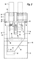
- a machine stand 10 forming a machine bed has a lower base area 11 from which on two opposite sides two side walls 12, 13 extend upwards. Limit these side walls 12, 13 together with a transverse wall 14 connecting them a machining area 15 of the machine.
- One of the two Side walls 12, 13 on the side of the processing area 15 opposite side of the transverse wall 14 connecting stator area 16 contains a designed as a drum magazine Tool magazine 17, the center of this stand area 16, that is essentially midway between the two Side walls 12, 13 is arranged.
- a longitudinal slide 21 is by means of three guide elements 22 horizontally longitudinally displaceable on the two guide rails 18, 19 guided. This creates a stable 3-point support reached. This longitudinal slide is supported 21 over two of these guide elements 22, which are apart are spaced apart on the longer guide rail 18 onwards. Overall, this longitudinal slide 21 therefore has one essentially triangular when viewed from above Shape.
- motor drive 23 drives a longitudinal spindle 24 through which the longitudinal slide 21 in the longitudinal direction is movable by motor.
- the longitudinal slide 21 faces the processing area 15 facing front two arranged one above the other and in the longitudinal direction of the guide rails 18, 19 mutually offset cross rails 25 on which a Cross slide 26 by means of guide elements 27 transverse to the direction of movement of the longitudinal slide 21 horizontally displaceable is led.
- a Cross slide 26 by means of guide elements 27 transverse to the direction of movement of the longitudinal slide 21 horizontally displaceable is led.
- the motor drive of the cross slide 26 takes place via a drive motor arranged on the longitudinal slide 28, which drives a cross spindle 29.
- the cross slide 26 has an integrated machining head on that cannot be moved vertically in or on Cross slide 26 is arranged.
- a drive motor 30 for the machining head protrudes from the cross slide 26 at the top out, and a tool spindle 31 is below the Cross slide 26 arranged on this and is used for receiving of tools. It is represented by a not shown Arrangement inside the cross slide 26 from Drive motor 30 driven.
- Fig. 1 there are two additional ones Longitudinal positions of the cross slide 26 and the tool spindle 31 shown in dash-dotted lines, while in Fig. 2 shows a second transverse position in dash-dotted lines is.
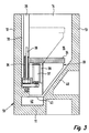
- two vertical guide rails 32 are arranged, on which a workpiece table or processing table 33 with horizontal workpiece holding plate 34 by means of Guide elements 35 is guided vertically.
- the vertical guide rails 32 but also on the opposite side wall 13 be arranged.
- the two guide rails 32 are sunk arranged in the side wall 12 so that the Processing table 33 also in a vertical channel 36 engages this side wall 12.
- a drive motor 37 Vertical spindle or lifting spindle 38, the middle arranged between the vertical guide rails 32 is.
- the stationary connected to the machine stand 10 Drive motor 37 engages in that shown in FIG. 3 lowest position of the processing table 33 from below forth in a cavity 39 of the same.
- the drive motor 37 could also be configured attached to the outside of the machine bed or machine stand 10 his.
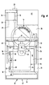
- the tool magazine 10 is part a tool changing device in the two side walls 12, 13 interconnecting stand area 16 arranged. Between the processing area 15 and a corresponding cavity for the tool magazine 17th 2 is a through opening open at the top 45 provided in the transverse wall 14. Hereby can the tool spindle 31 be moved into this through opening 45 to the to store previous tool in tool magazine 17 and after corresponding rotation of this tool magazine 17 to pick up a new desired tool.
- the stand area 16 is open at its rear end, to make changing tools easier. This Of course, opening can also be done through a flap, Door or the like to be covered.
- the processing machine is in a housing 46 arranged, the in a manner not shown by the processing side 47 forth access to the processing area 15 thereby enables that sliding, folding or Rolling doors are provided.
- a flexible cable channel 48 from the Horizontal slide assembly from back to the To ensure power supply to the carriage assembly.
- a control cabinet 51 is arranged in this cavity, the machine control or at least parts of the Machine control can contain, but here additionally Accommodation options for spare parts and accessories consist.
Priority Applications (5)
| Application Number | Priority Date | Filing Date | Title |
|---|---|---|---|
| EP99109993A EP1057582B1 (fr) | 1999-05-21 | 1999-05-21 | Machines d'usinage, en particulier machine foreuse et/ou fraiseuse |
| AT99109993T ATE223784T1 (de) | 1999-05-21 | 1999-05-21 | Bearbeitungsmaschine, insbesondere bohr- und/oder fräsmaschine |
| DE59902650T DE59902650D1 (de) | 1999-05-21 | 1999-05-21 | Bearbeitungsmaschine, insbesondere Bohr- und/oder Fräsmaschine |
| US09/503,325 US6200247B1 (en) | 1999-05-21 | 2000-02-14 | Machine tool with tool changer |
| JP2000094712A JP2000326160A (ja) | 1999-05-21 | 2000-03-30 | 工作機械 |
Applications Claiming Priority (1)
| Application Number | Priority Date | Filing Date | Title |
|---|---|---|---|
| EP99109993A EP1057582B1 (fr) | 1999-05-21 | 1999-05-21 | Machines d'usinage, en particulier machine foreuse et/ou fraiseuse |
Publications (2)
| Publication Number | Publication Date |
|---|---|
| EP1057582A1 true EP1057582A1 (fr) | 2000-12-06 |
| EP1057582B1 EP1057582B1 (fr) | 2002-09-11 |
Family
ID=8238219
Family Applications (1)
| Application Number | Title | Priority Date | Filing Date |
|---|---|---|---|
| EP99109993A Expired - Lifetime EP1057582B1 (fr) | 1999-05-21 | 1999-05-21 | Machines d'usinage, en particulier machine foreuse et/ou fraiseuse |
Country Status (5)
| Country | Link |
|---|---|
| US (1) | US6200247B1 (fr) |
| EP (1) | EP1057582B1 (fr) |
| JP (1) | JP2000326160A (fr) |
| AT (1) | ATE223784T1 (fr) |
| DE (1) | DE59902650D1 (fr) |
Cited By (5)
| Publication number | Priority date | Publication date | Assignee | Title |
|---|---|---|---|---|
| DE10139296A1 (de) * | 2001-08-09 | 2003-03-06 | Albeck Gmbh | Spannvorrichtung für mehrseitig zu bearbeitende Werkstücke |
| CN101491862A (zh) * | 2008-01-12 | 2009-07-29 | 通快机床两合公司 | 具有喷嘴更换装置的激光加工机 |
| CN104227346A (zh) * | 2014-08-22 | 2014-12-24 | 南通力科机床制造有限公司 | 一种立式升降台铣床工作台底座的加工工艺 |
| CN105817682A (zh) * | 2016-01-12 | 2016-08-03 | 北京霍尔茨门业股份有限公司 | 一种收口条自动铣槽机 |
| CN105935793A (zh) * | 2016-05-25 | 2016-09-14 | 深圳市联得自动化装备股份有限公司 | 雕铣机及其控制方法 |
Families Citing this family (9)
| Publication number | Priority date | Publication date | Assignee | Title |
|---|---|---|---|---|
| JP4331525B2 (ja) * | 2003-07-18 | 2009-09-16 | アイシン・エィ・ダブリュ株式会社 | マシニングセンタ |
| DE102006037437B4 (de) * | 2006-08-09 | 2009-04-02 | Haas Schleifmaschinen Gmbh | Werkzeugmaschine |
| CN102266976B (zh) * | 2011-07-07 | 2013-07-10 | 缙云县高新机械制造有限公司 | 一种立式内拉床的工作台结构 |
| CN104827302A (zh) * | 2015-05-06 | 2015-08-12 | 广州泰胜数控机械有限公司 | 一种双机头多用途单边机床 |
| CN104827301A (zh) * | 2015-05-06 | 2015-08-12 | 广州泰胜数控机械有限公司 | 一种机床 |
| CN105436897B (zh) * | 2015-12-30 | 2018-05-29 | 北京朗格贝通自动化设备有限公司 | 一种多功能钣箱加工中心 |
| CN108372443A (zh) * | 2017-12-30 | 2018-08-07 | 宁波隆兴电信设备制造有限公司 | 一种光缆分纤箱焊接产品的打磨工装 |
| CN108637393A (zh) * | 2018-05-11 | 2018-10-12 | 宁波凯米协尔机床有限公司 | 一种可快速装配的加工中心光机 |
| TWM575742U (zh) * | 2018-11-07 | 2019-03-21 | 達佛羅企業有限公司 | 可替換工件的加工裝置 |
Citations (5)
| Publication number | Priority date | Publication date | Assignee | Title |
|---|---|---|---|---|
| US4621407A (en) * | 1983-07-15 | 1986-11-11 | Fuji Seiki Machine Works, Ltd. | Body for machining center |
| EP0642867A1 (fr) * | 1993-09-10 | 1995-03-15 | Charmilles Technologies S.A. | Structure pour machine d'électroérosion |
| US5439431A (en) * | 1992-04-10 | 1995-08-08 | Emag-Maschinen Vertriebs - Und Service Gmbh | Machining centre constructed from assemblies |
| US5678291A (en) * | 1994-11-19 | 1997-10-21 | Maschinenfabrik Berthold Hermle Ag | Machine tool |
| EP0816012A1 (fr) * | 1996-06-26 | 1998-01-07 | Starrfräsmaschinen AG | Centre d'usinage rigide |
Family Cites Families (9)
| Publication number | Priority date | Publication date | Assignee | Title |
|---|---|---|---|---|
| SU626897A1 (ru) * | 1976-03-26 | 1978-10-05 | Ордена Трудового Красного Знамени Экспериментальный Научно-Исследовательский Институт Металлорежущих Станков | Горизонтально-фрезерный станок |
| IL60089A0 (en) * | 1980-05-16 | 1980-07-31 | Israel Nachmany | Improvements relating to the structure of automatic machine tools |
| JPS57189748A (en) * | 1981-05-13 | 1982-11-22 | Tsugami Corp | Horizontal machining center |
| JPS6186144A (ja) * | 1984-10-03 | 1986-05-01 | Mazda Motor Corp | マシニングセンタ |
| DE3447706A1 (de) * | 1984-12-28 | 1986-07-03 | Maho Werkzeugmaschinenbau Babel & Co, 8962 Pfronten | Werkzeugmagazin |
| JP2535154B2 (ja) * | 1986-10-24 | 1996-09-18 | 株式会社 森精機製作所 | 立形マシニングセンタ |
| DE4441253A1 (de) * | 1994-11-19 | 1996-05-23 | Hermle Berthold Maschf Ag | Werkzeugmaschine, insbesondere Bohr- und Fräsmaschine |
| DE4444614A1 (de) * | 1994-12-14 | 1996-06-20 | Deckel Maho Gmbh | Werkzeugmaschine |
| DE19641831B4 (de) * | 1996-10-10 | 2007-02-08 | Deckel Maho Pfronten Gmbh | Universal-Fräs- und Bohrmaschine |
-
1999
- 1999-05-21 DE DE59902650T patent/DE59902650D1/de not_active Expired - Fee Related
- 1999-05-21 AT AT99109993T patent/ATE223784T1/de not_active IP Right Cessation
- 1999-05-21 EP EP99109993A patent/EP1057582B1/fr not_active Expired - Lifetime
-
2000
- 2000-02-14 US US09/503,325 patent/US6200247B1/en not_active Expired - Fee Related
- 2000-03-30 JP JP2000094712A patent/JP2000326160A/ja active Pending
Patent Citations (5)
| Publication number | Priority date | Publication date | Assignee | Title |
|---|---|---|---|---|
| US4621407A (en) * | 1983-07-15 | 1986-11-11 | Fuji Seiki Machine Works, Ltd. | Body for machining center |
| US5439431A (en) * | 1992-04-10 | 1995-08-08 | Emag-Maschinen Vertriebs - Und Service Gmbh | Machining centre constructed from assemblies |
| EP0642867A1 (fr) * | 1993-09-10 | 1995-03-15 | Charmilles Technologies S.A. | Structure pour machine d'électroérosion |
| US5678291A (en) * | 1994-11-19 | 1997-10-21 | Maschinenfabrik Berthold Hermle Ag | Machine tool |
| EP0816012A1 (fr) * | 1996-06-26 | 1998-01-07 | Starrfräsmaschinen AG | Centre d'usinage rigide |
Cited By (10)
| Publication number | Priority date | Publication date | Assignee | Title |
|---|---|---|---|---|
| DE10139296A1 (de) * | 2001-08-09 | 2003-03-06 | Albeck Gmbh | Spannvorrichtung für mehrseitig zu bearbeitende Werkstücke |
| DE10139296B4 (de) * | 2001-08-09 | 2005-03-24 | Albeck Gmbh | Spannvorrichtung für mehrseitig zu bearbeitende Werkstücke |
| CN101491862A (zh) * | 2008-01-12 | 2009-07-29 | 通快机床两合公司 | 具有喷嘴更换装置的激光加工机 |
| US8366593B2 (en) | 2008-01-12 | 2013-02-05 | Trumpf Werkzeugmaschinen Gmbh + Co. Kg | Laser nozzle changing device |
| CN101491862B (zh) * | 2008-01-12 | 2013-08-28 | 通快机床两合公司 | 具有喷嘴更换装置的激光加工机 |
| US8814770B2 (en) | 2008-01-12 | 2014-08-26 | Trumpf Werkzeugmaschinen Gmbh + Co. Kg | Laser nozzle changing device |
| CN104227346A (zh) * | 2014-08-22 | 2014-12-24 | 南通力科机床制造有限公司 | 一种立式升降台铣床工作台底座的加工工艺 |
| CN105817682A (zh) * | 2016-01-12 | 2016-08-03 | 北京霍尔茨门业股份有限公司 | 一种收口条自动铣槽机 |
| CN105817682B (zh) * | 2016-01-12 | 2017-09-29 | 北京霍尔茨门业股份有限公司 | 一种收口条自动铣槽机 |
| CN105935793A (zh) * | 2016-05-25 | 2016-09-14 | 深圳市联得自动化装备股份有限公司 | 雕铣机及其控制方法 |
Also Published As
| Publication number | Publication date |
|---|---|
| EP1057582B1 (fr) | 2002-09-11 |
| ATE223784T1 (de) | 2002-09-15 |
| DE59902650D1 (de) | 2002-10-17 |
| US6200247B1 (en) | 2001-03-13 |
| JP2000326160A (ja) | 2000-11-28 |
Similar Documents
| Publication | Publication Date | Title |
|---|---|---|
| EP2623255B1 (fr) | Machine-outil universelle avec espace de collecte des copeaux | |
| EP0712683B1 (fr) | Machine-outil, en particulier perceuse-fraiseuse | |
| EP0712682B1 (fr) | Machine-outil, en particulier perceuse-fraiseuse | |
| EP0452735B1 (fr) | Centre d'usinage | |
| EP1695791B1 (fr) | Machine d'usinage avec plusieurs broches parallèles | |
| EP1882544B1 (fr) | Fraiseuse et perceuse | |
| EP1057582B1 (fr) | Machines d'usinage, en particulier machine foreuse et/ou fraiseuse | |
| EP2747936B1 (fr) | Machine-outil | |
| DE3734716C1 (de) | Schutzabdeckung | |
| DE10045176A1 (de) | Werkzeugmaschine | |
| EP1324856B1 (fr) | Machine-outil a colonne | |
| DE4113629C2 (de) | Reihenbohr- und Fräsmaschine | |
| DE10012445A1 (de) | Bearbeitungszentrum | |
| DE102009041596A1 (de) | Werkzeugmaschine | |
| EP1125677B1 (fr) | Machine-outil universelle | |
| EP1525065B1 (fr) | Machine-outil dotee de deux broches porte-pieces | |
| DE4136916C2 (de) | Mehrspindel-Drehmaschine | |
| DE2514615A1 (de) | Bohr- und fraeswerk | |
| DE102010045151B4 (de) | Doppelspindlige Werkzeugmaschine | |
| DE102007054267A1 (de) | Mehrspindel-Bearbeitungsmaschine | |
| DE3742042C1 (de) | Maschinenbett fuer eine Drehmaschine mit axial verschiebbarem Spindelstock | |
| DE3824572C2 (fr) | ||
| EP0949042B1 (fr) | Machine-outil,en particulier perceuse-fraiseuse | |
| DE4117723A1 (de) | Arbeitsmaschine zur behandlung von werkstuecken, insbesondere werkzeugmaschine | |
| DE10354706C5 (de) | Werkzeugmaschine mit Transportvorrichtung |
Legal Events
| Date | Code | Title | Description |
|---|---|---|---|
| PUAI | Public reference made under article 153(3) epc to a published international application that has entered the european phase |
Free format text: ORIGINAL CODE: 0009012 |
|
| 17P | Request for examination filed |
Effective date: 19991126 |
|
| AK | Designated contracting states |
Kind code of ref document: A1 Designated state(s): AT CH DE FR GB IT LI |
|
| AX | Request for extension of the european patent |
Free format text: AL;LT;LV;MK;RO;SI |
|
| AKX | Designation fees paid |
Free format text: AT CH DE FR GB IT LI |
|
| GRAG | Despatch of communication of intention to grant |
Free format text: ORIGINAL CODE: EPIDOS AGRA |
|
| 17Q | First examination report despatched |
Effective date: 20011227 |
|
| GRAG | Despatch of communication of intention to grant |
Free format text: ORIGINAL CODE: EPIDOS AGRA |
|
| GRAH | Despatch of communication of intention to grant a patent |
Free format text: ORIGINAL CODE: EPIDOS IGRA |
|
| GRAH | Despatch of communication of intention to grant a patent |
Free format text: ORIGINAL CODE: EPIDOS IGRA |
|
| GRAA | (expected) grant |
Free format text: ORIGINAL CODE: 0009210 |
|
| AK | Designated contracting states |
Kind code of ref document: B1 Designated state(s): AT CH DE FR GB IT LI |
|
| REF | Corresponds to: |
Ref document number: 223784 Country of ref document: AT Date of ref document: 20020915 Kind code of ref document: T |
|
| REG | Reference to a national code |
Ref country code: GB Ref legal event code: FG4D Free format text: NOT ENGLISH |
|
| REG | Reference to a national code |
Ref country code: CH Ref legal event code: EP |
|
| REG | Reference to a national code |
Ref country code: CH Ref legal event code: NV Representative=s name: TROESCH SCHEIDEGGER WERNER AG |
|
| GBT | Gb: translation of ep patent filed (gb section 77(6)(a)/1977) |
Effective date: 20020911 |
|
| REF | Corresponds to: |
Ref document number: 59902650 Country of ref document: DE Date of ref document: 20021017 |
|
| ET | Fr: translation filed | ||
| PLBE | No opposition filed within time limit |
Free format text: ORIGINAL CODE: 0009261 |
|
| STAA | Information on the status of an ep patent application or granted ep patent |
Free format text: STATUS: NO OPPOSITION FILED WITHIN TIME LIMIT |
|
| 26N | No opposition filed |
Effective date: 20030612 |
|
| PGFP | Annual fee paid to national office [announced via postgrant information from national office to epo] |
Ref country code: DE Payment date: 20080429 Year of fee payment: 10 |
|
| PGFP | Annual fee paid to national office [announced via postgrant information from national office to epo] |
Ref country code: AT Payment date: 20080527 Year of fee payment: 10 |
|
| PGFP | Annual fee paid to national office [announced via postgrant information from national office to epo] |
Ref country code: IT Payment date: 20080522 Year of fee payment: 10 |
|
| PGFP | Annual fee paid to national office [announced via postgrant information from national office to epo] |
Ref country code: CH Payment date: 20080725 Year of fee payment: 10 |
|
| PGFP | Annual fee paid to national office [announced via postgrant information from national office to epo] |
Ref country code: GB Payment date: 20080416 Year of fee payment: 10 |
|
| REG | Reference to a national code |
Ref country code: CH Ref legal event code: PL |
|
| GBPC | Gb: european patent ceased through non-payment of renewal fee |
Effective date: 20090521 |
|
| PG25 | Lapsed in a contracting state [announced via postgrant information from national office to epo] |
Ref country code: LI Free format text: LAPSE BECAUSE OF NON-PAYMENT OF DUE FEES Effective date: 20090531 Ref country code: CH Free format text: LAPSE BECAUSE OF NON-PAYMENT OF DUE FEES Effective date: 20090531 Ref country code: AT Free format text: LAPSE BECAUSE OF NON-PAYMENT OF DUE FEES Effective date: 20090521 |
|
| REG | Reference to a national code |
Ref country code: FR Ref legal event code: ST Effective date: 20100129 |
|
| PG25 | Lapsed in a contracting state [announced via postgrant information from national office to epo] |
Ref country code: FR Free format text: LAPSE BECAUSE OF NON-PAYMENT OF DUE FEES Effective date: 20090602 |
|
| PGFP | Annual fee paid to national office [announced via postgrant information from national office to epo] |
Ref country code: FR Payment date: 20080519 Year of fee payment: 10 |
|
| PG25 | Lapsed in a contracting state [announced via postgrant information from national office to epo] |
Ref country code: GB Free format text: LAPSE BECAUSE OF NON-PAYMENT OF DUE FEES Effective date: 20090521 |
|
| PG25 | Lapsed in a contracting state [announced via postgrant information from national office to epo] |
Ref country code: DE Free format text: LAPSE BECAUSE OF NON-PAYMENT OF DUE FEES Effective date: 20091201 |
|
| PG25 | Lapsed in a contracting state [announced via postgrant information from national office to epo] |
Ref country code: IT Free format text: LAPSE BECAUSE OF NON-PAYMENT OF DUE FEES Effective date: 20090521 |