EP1525065B1 - Machine-outil dotee de deux broches porte-pieces - Google Patents
Machine-outil dotee de deux broches porte-pieces Download PDFInfo
- Publication number
- EP1525065B1 EP1525065B1 EP03766271A EP03766271A EP1525065B1 EP 1525065 B1 EP1525065 B1 EP 1525065B1 EP 03766271 A EP03766271 A EP 03766271A EP 03766271 A EP03766271 A EP 03766271A EP 1525065 B1 EP1525065 B1 EP 1525065B1
- Authority
- EP
- European Patent Office
- Prior art keywords
- spindle
- guide
- machine tool
- slide
- workpiece
- Prior art date
- Legal status (The legal status is an assumption and is not a legal conclusion. Google has not performed a legal analysis and makes no representation as to the accuracy of the status listed.)
- Expired - Lifetime
Links
Images


Classifications
-
- B—PERFORMING OPERATIONS; TRANSPORTING
- B23—MACHINE TOOLS; METAL-WORKING NOT OTHERWISE PROVIDED FOR
- B23Q—DETAILS, COMPONENTS, OR ACCESSORIES FOR MACHINE TOOLS, e.g. ARRANGEMENTS FOR COPYING OR CONTROLLING; MACHINE TOOLS IN GENERAL CHARACTERISED BY THE CONSTRUCTION OF PARTICULAR DETAILS OR COMPONENTS; COMBINATIONS OR ASSOCIATIONS OF METAL-WORKING MACHINES, NOT DIRECTED TO A PARTICULAR RESULT
- B23Q39/00—Metal-working machines incorporating a plurality of sub-assemblies, each capable of performing a metal-working operation
- B23Q39/04—Metal-working machines incorporating a plurality of sub-assemblies, each capable of performing a metal-working operation the sub-assemblies being arranged to operate simultaneously at different stations, e.g. with an annular work-table moved in steps
-
- B—PERFORMING OPERATIONS; TRANSPORTING
- B23—MACHINE TOOLS; METAL-WORKING NOT OTHERWISE PROVIDED FOR
- B23B—TURNING; BORING
- B23B3/00—General-purpose turning-machines or devices, e.g. centre lathes with feed rod and lead screw; Sets of turning-machines
- B23B3/30—Turning-machines with two or more working-spindles, e.g. in fixed arrangement
-
- B—PERFORMING OPERATIONS; TRANSPORTING
- B23—MACHINE TOOLS; METAL-WORKING NOT OTHERWISE PROVIDED FOR
- B23Q—DETAILS, COMPONENTS, OR ACCESSORIES FOR MACHINE TOOLS, e.g. ARRANGEMENTS FOR COPYING OR CONTROLLING; MACHINE TOOLS IN GENERAL CHARACTERISED BY THE CONSTRUCTION OF PARTICULAR DETAILS OR COMPONENTS; COMBINATIONS OR ASSOCIATIONS OF METAL-WORKING MACHINES, NOT DIRECTED TO A PARTICULAR RESULT
- B23Q1/00—Members which are comprised in the general build-up of a form of machine, particularly relatively large fixed members
- B23Q1/25—Movable or adjustable work or tool supports
- B23Q1/44—Movable or adjustable work or tool supports using particular mechanisms
- B23Q1/56—Movable or adjustable work or tool supports using particular mechanisms with sliding pairs only, the sliding pairs being the first two elements of the mechanism
- B23Q1/60—Movable or adjustable work or tool supports using particular mechanisms with sliding pairs only, the sliding pairs being the first two elements of the mechanism two sliding pairs only, the sliding pairs being the first two elements of the mechanism
- B23Q1/62—Movable or adjustable work or tool supports using particular mechanisms with sliding pairs only, the sliding pairs being the first two elements of the mechanism two sliding pairs only, the sliding pairs being the first two elements of the mechanism with perpendicular axes, e.g. cross-slides
- B23Q1/621—Movable or adjustable work or tool supports using particular mechanisms with sliding pairs only, the sliding pairs being the first two elements of the mechanism two sliding pairs only, the sliding pairs being the first two elements of the mechanism with perpendicular axes, e.g. cross-slides a single sliding pair followed perpendicularly by a single sliding pair
- B23Q1/625—Movable or adjustable work or tool supports using particular mechanisms with sliding pairs only, the sliding pairs being the first two elements of the mechanism two sliding pairs only, the sliding pairs being the first two elements of the mechanism with perpendicular axes, e.g. cross-slides a single sliding pair followed perpendicularly by a single sliding pair followed parallelly by a single rotating pair
-
- Y—GENERAL TAGGING OF NEW TECHNOLOGICAL DEVELOPMENTS; GENERAL TAGGING OF CROSS-SECTIONAL TECHNOLOGIES SPANNING OVER SEVERAL SECTIONS OF THE IPC; TECHNICAL SUBJECTS COVERED BY FORMER USPC CROSS-REFERENCE ART COLLECTIONS [XRACs] AND DIGESTS
- Y10—TECHNICAL SUBJECTS COVERED BY FORMER USPC
- Y10T—TECHNICAL SUBJECTS COVERED BY FORMER US CLASSIFICATION
- Y10T29/00—Metal working
- Y10T29/51—Plural diverse manufacturing apparatus including means for metal shaping or assembling
- Y10T29/5104—Type of machine
- Y10T29/5109—Lathe
- Y10T29/5114—Lathe and tool
-
- Y—GENERAL TAGGING OF NEW TECHNOLOGICAL DEVELOPMENTS; GENERAL TAGGING OF CROSS-SECTIONAL TECHNOLOGIES SPANNING OVER SEVERAL SECTIONS OF THE IPC; TECHNICAL SUBJECTS COVERED BY FORMER USPC CROSS-REFERENCE ART COLLECTIONS [XRACs] AND DIGESTS
- Y10—TECHNICAL SUBJECTS COVERED BY FORMER USPC
- Y10T—TECHNICAL SUBJECTS COVERED BY FORMER US CLASSIFICATION
- Y10T409/00—Gear cutting, milling, or planing
- Y10T409/30—Milling
- Y10T409/304536—Milling including means to infeed work to cutter
- Y10T409/305544—Milling including means to infeed work to cutter with work holder
- Y10T409/305656—Milling including means to infeed work to cutter with work holder including means to support work for rotation during operation
-
- Y—GENERAL TAGGING OF NEW TECHNOLOGICAL DEVELOPMENTS; GENERAL TAGGING OF CROSS-SECTIONAL TECHNOLOGIES SPANNING OVER SEVERAL SECTIONS OF THE IPC; TECHNICAL SUBJECTS COVERED BY FORMER USPC CROSS-REFERENCE ART COLLECTIONS [XRACs] AND DIGESTS
- Y10—TECHNICAL SUBJECTS COVERED BY FORMER USPC
- Y10T—TECHNICAL SUBJECTS COVERED BY FORMER US CLASSIFICATION
- Y10T82/00—Turning
- Y10T82/25—Lathe
- Y10T82/2508—Lathe with tool turret
-
- Y—GENERAL TAGGING OF NEW TECHNOLOGICAL DEVELOPMENTS; GENERAL TAGGING OF CROSS-SECTIONAL TECHNOLOGIES SPANNING OVER SEVERAL SECTIONS OF THE IPC; TECHNICAL SUBJECTS COVERED BY FORMER USPC CROSS-REFERENCE ART COLLECTIONS [XRACs] AND DIGESTS
- Y10—TECHNICAL SUBJECTS COVERED BY FORMER USPC
- Y10T—TECHNICAL SUBJECTS COVERED BY FORMER US CLASSIFICATION
- Y10T82/00—Turning
- Y10T82/25—Lathe
- Y10T82/2511—Vertical
-
- Y—GENERAL TAGGING OF NEW TECHNOLOGICAL DEVELOPMENTS; GENERAL TAGGING OF CROSS-SECTIONAL TECHNOLOGIES SPANNING OVER SEVERAL SECTIONS OF THE IPC; TECHNICAL SUBJECTS COVERED BY FORMER USPC CROSS-REFERENCE ART COLLECTIONS [XRACs] AND DIGESTS
- Y10—TECHNICAL SUBJECTS COVERED BY FORMER USPC
- Y10T—TECHNICAL SUBJECTS COVERED BY FORMER US CLASSIFICATION
- Y10T82/00—Turning
- Y10T82/25—Lathe
- Y10T82/2514—Lathe with work feeder or remover
-
- Y—GENERAL TAGGING OF NEW TECHNOLOGICAL DEVELOPMENTS; GENERAL TAGGING OF CROSS-SECTIONAL TECHNOLOGIES SPANNING OVER SEVERAL SECTIONS OF THE IPC; TECHNICAL SUBJECTS COVERED BY FORMER USPC CROSS-REFERENCE ART COLLECTIONS [XRACs] AND DIGESTS
- Y10—TECHNICAL SUBJECTS COVERED BY FORMER USPC
- Y10T—TECHNICAL SUBJECTS COVERED BY FORMER US CLASSIFICATION
- Y10T82/00—Turning
- Y10T82/25—Lathe
- Y10T82/2524—Multiple
Definitions
- the invention relates to a multi-spindle machine tool, comprising a machine frame, a first spindle slide with a first workpiece spindle and a second spindle slide with a second workpiece spindle, said first spindle slide and second spindle slide are guided linearverschietons on the machine frame, a first guide and a spaced second guide, which are arranged on the machine frame, wherein the first workpiece spindle and the second workpiece spindle are arranged between the two guides, and a tool receiving device.
- a multi-spindle lathe with at least two rectified parallel juxtaposed slidably mounted workpiece spindle units and a stationary tool carrier is known.
- the workpiece spindle units can be moved independently of each other.
- the invention has for its object to provide a multi-spindle machine tool, which is simple with minimal space requirements with respect to the plurality of workpiece spindles.
- both the first spindle slide and the second spindle slide are guided on the first guide and the second guide that the first spindle slide has a first leg which is oriented along the first guide is, and has a second leg, which is oriented transversely to the first guide, wherein the second leg of the first spindle slide is coupled to the second guide, and that the second spindle slide has a first leg, which is oriented along the second guide, and a second leg which is oriented transversely to the second guide, wherein the second leg of the second spindle slide is coupled to the first guide.
- the spindle slides are guided on the same guides. As a result, it is not necessary that the spindle slides are supported against each other. Since, according to the invention, the two workpiece spindles are arranged between the two guides, the space requirement for the workpiece spindles can be minimized since this intermediate area is used for the arrangement of the workpiece spindles and no support arrangement between the two spindle slides is necessary.
- a simpler machine structure can be realized if the first spindle slide and the second spindle slide are mechanically uncoupled, resulting in manufacturing advantages in the production of the multi-spindle machine tool according to the invention. Since then a support between the two spindle slide is not provided, the number of wearing parts and in particular guides is minimized, so that the maintenance is minimized.
- the first and second spindle slide has an L-shaped or triangular shape, in particular with a first leg, which is oriented along the first and second guide, and with a second leg, which transverse to the first or second leadership is oriented.
- a high stability and rigidity of the spindle slide is provided so that they can hold the associated workpiece spindles and high-precision machining operations are feasible.
- the two spindle slides can then be juxtaposed, so that the L-shape or approximated triangular shape complement each other. This in turn allows the workpiece spindles to be positioned optimally in space between the two guides.
- the L-shape or triangular shape refers to at least a portion of the corresponding spindle slide near the guides in a projection on these guides.
- the second leg of the first spindle slide or the second spindle slide is coupled to the second or first guide so as to enable a displacement of both spindle slides on the same guides.
- a high stability with respect to the arrangement of the workpiece spindles on the associated spindle slide can be achieved if the first or second spindle slide has a larger contact surface with the first or second guide than with the second or first guide.
- both the first spindle slide and the second Spindle slides on the same guides are feasible.
- an area can then be provided on the first spindle slide or the second spindle slide in order to hold the associated workpiece spindles.
- the first or second spindle slide then has a larger number of guide shoes for the first and second guide than for the second or first guide, respectively, in order accordingly to provide the larger contact surfaces for the first and second guide.
- first or second workpiece spindle sits between and / or on the two legs of the respective spindle slide. This makes it possible to ensure that the respective workpiece spindles are associated with one another between the two guides, thus minimizing the space requirement for the workpiece spindles with high stability of their displacement guidance on the guides and high rigidity of the arrangement.
- the two guides are parallel to each other, so as to allow in a simple manner a linear displacement of the two spindle slides.
- the guides comprise guide rails on which the spindle slides are then guided via corresponding guide shoes.
- the displacement direction (Z direction) of a workpiece spindle is transverse and in particular perpendicular to a displacement direction (X direction) of the associated spindle slide.
- About the spindle slide can then be a supply and removal of workpieces to achieve the tools and beyond a fine positioning of the workpieces relative to the tools, and on the workpiece spindles can vary the height distance between tools and workpieces.
- the first and second guides are arranged horizontally aligned on the machine frame. It can then be realized in a simple manner a vertical machining of a workpiece, in which case in particular the workpiece spindles are guided vertically to the associated spindle slide.
- the tool receiving device has a first tool holder and a second tool holder, so that two workpieces can be processed simultaneously with two different tools (which may be identical).
- the two tool holders are conveniently arranged between the two guides.
- the two tool holders are arranged on a rocker so that they can be moved synchronously and in particular can be pivoted relative to the machine frame and thus to the workpiece spindles.
- a variety of processing options of a workpiece arise when the tool receiving device is pivotally mounted on the machine frame and then about an axis transverse and / or parallel to the direction of displacement of the spindle carriage is pivotable. It can be in this way, for example, produce programmable tracks for a Gleichl ufgelenk as a workpiece. It can be performed milling operations in a defined angular position with respect to a Z-direction, the direction of displacement of the workpiece spindles.
- the movement of the spindle slides, the workpiece spindles and the tool receiving device is controlled in particular programmable, so as to be able to edit a workpiece controlled in a highly precise manner.
- the two spindle slides are controlled synchronously or independently of each other movable.
- a synchronous movement is advantageous, for example, if a larger path is to be crossed in short times without the highest precision being required. For example, in the recording of workpieces to be machined and in the delivery of machined workpieces, this is advantageous. If a high-precision machining is necessary, then it is cheaper if the spindle slides are independently controlled to be movable independently so as to be able to carry out, for example, correction movements independently of one another.
- the corresponding movement modes of the two spindle slides are preferably controlled by a control device.
- the two workpiece spindles are synchronously or independently controlled to move. This movement can be controlled in the X direction and / or Z direction (via the workpiece spindles).
- a support guide for the first spindle slide and / or second spindle slide is provided.
- a support guide in addition to the first and second guide is particularly advantageous when provided for driving the spindle slide linear motors.
- Linear motors cause large forces, which can be in the order of 40,000 N.
- About the support guide can absorb such forces.
- the support guide is arranged and designed so that forces exerted by a linear motor can be absorbed while horizontal and vertical forces can be absorbed.
- the support guide is arranged above the first guide and second guide for the spindle slide.
- a space is provided on which the linear motor can be arranged, namely just between the support guide and the first and second guide.
- the support guide comprises a first guide device, which is arranged with an extension in the direction of displacement on the associated spindle slide, and a second corresponding guide device, which is arranged on the machine frame.
- a linear motor for the associated spindle slide is seated between the support guide and the first guide or second guide.
- a primary part can be arranged on the carriage, specifically below the support guide, and a secondary part can be arranged on the machine frame, again below the support guide.
- the first guide member is seated on a side wall of the associated spindle carriage, so that the mass of a spindle carriage need not be substantially increased when an additional support guide is provided.
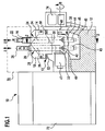
- An embodiment of a multi-spindle machine tool according to the invention is a two-spindle machine tool, which is designated in Figure 1 as a whole with 10; it comprises a machine frame 12, via which the multi-spindle machine tool 10 can be positioned aligned on a base.
- a first spindle slide 14 is guided linearly displaceable in a direction X on an attachment stand 13. This direction X is in particular a horizontal direction.
- the first spindle slide 14 carries a first workpiece spindle 16, on which a workpiece to be machined is rotatably fixable.
- the first workpiece spindle 16 is displaceably guided on the first spindle slide 14 in a transverse direction Z to the direction X, so that the distance of a workpiece held on the first workpiece spindle 16 relative to the machine frame 12 is adjustable.
- An axis of rotation of the first workpiece spindle 16 about which a held workpiece is rotatable is parallel to the Z direction.
- a second spindle slide 18 is provided, which is also guided in the X direction linearly displaceable on the machine frame 12.
- This second spindle slide 18 holds a second workpiece spindle 20, which is held in the Z-direction linearly displaceable on the second spindle slide 18.
- the two workpiece spindles 16 and 20 are in particular aligned substantially parallel to each other.
- a first drive 22 For driving the first workpiece spindle 16 in its displacement movement along the Z-axis, a first drive 22 is provided. It may be, for example, a hydraulic drive, a ball screw or a linear motor. A drive unit of the first drive 22 is seated on the first spindle slide 14 and is moved along with it in the X direction.
- the first spindle slide 14 has a guide device designated as a whole by 24, on which the first workpiece spindle 16 is displaceable in the Z direction driven by the first drive 22.
- the Z-direction is in particular vertically aligned, that is parallel to the direction of gravity.
- a second drive 26 is provided, which drives the linear displacement of the second workpiece spindle 20 on a guide device 28 in the Z direction relative to the second spindle slide 18.
- the workpiece spindles 16 and 20 are each provided with a workpiece holder 30, 32, on which the respective workpieces are rotatably fixable about longitudinal axes 34, 36 of the respective workpiece spindles 16, 20.
- a tool receiving device 38 is arranged, for example, pivotable, wherein a pivot axis 40 is oriented transversely to the Z direction and X direction and in particular is oriented horizontally.
- the tool receiving device 38 comprises in a two-spindle machine tool a first tool holder 42 and a second tool holder 44 which are spaced from each other.
- the tool holders 42, 44 are seated on rotatably driven tool spindles 43, 45, so that the corresponding held tools such as milling tools or drilling tools are rotatable about a spindle axis. It is then possible simultaneously to process two workpieces by means of respective tools, a first workpiece being held on the first workpiece spindle 16 and a second workpiece being held on the second workpiece spindle 20.
- each pivot position of the tool receiving device 38 is adjustable so that at a certain set pivot position (at a certain set pivot angle B) held on the workpiece spindles 16 and 20 workpieces on the fixed to the tool receiving device 38 and in particular in the tool holders 42, 44 existing tools are editable.
- a certain set pivot position at a certain set pivot angle B
- existing tools are editable.
- corresponding additional devices such as one or more rotary brackets 49 are provided with a corresponding turning steel ( Figure 2) or additional spindle, which are arranged in the region of the processing zone of the workpieces.
- first held on the first workpiece spindle 16 is processed with a first tool and then passed to the workpiece spindle 20 and then processed with a second tool.
- a pivoting space 48 is formed so that the tool receiving device 38 is freely pivotable on the machine frame 12 in a certain pivoting range.
- this pivotal space 48 can also dissipate chips and the like.
- a first guide 50 is provided, which in particular comprises a guide rail, which is arranged at a distance from the tool receiving device 38 above this.
- a second guide 52 is provided, which is spaced parallel to the first guide 50, in particular at the same height in the Z direction over the horrifrichtu ng 38 is arranged as the first guide 50.
- the second guide 52nd In particular, in turn comprises a guide rail.
- the two guides 50 and 52 are arranged in particular horizontally.
- the guides 50, 52 are seated on the attachment stand 13.
- the guides 50, 52 are arranged offset in the Z direction, so as to stiffen, for example, a spindle slide in its height direction, if necessary.
- the first spindle slide 14 is L-shaped or triangular in shape such that it comprises a first leg 54 which is oriented along the first guide 50 and guided thereon.
- first leg 54 which is oriented along the first guide 50 and guided thereon.
- two spaced guide shoes 56a, 56b are provided to guide the first leg 54 on the first guide 50 linearly displaceable.
- second leg 58 Connected to the first leg 54 is a second leg 58 which is oriented transversely to the first leg 54 and which is coupled to the second guide 52, for example by means of a guide shoe 60, to guide the second leg 58 linearly displaceable on the second guide 52 ,
- the contact surface of the first spindle slide 14 with the first guide 50 for linearly displaceable coupling thereto is larger than the contact surface for coupling to the second guide 52.
- the first contact surface is formed over the two guide shoes 56a, 56b, while for the second guide 52nd is formed only over the one guide shoe 60.
- the second spindle slide 18 also includes a first leg 62, which is oriented along the second guide 52 and, for example, coupled thereto via two guide shoes 64a, 64b. Transverse to this first leg 62 sits a second leg 66, which is coupled to the first guide 50 via a guide shoe 68.
- the second spindle slide 18 has an L-shaped or triangular outer shape, wherein the contact surface with the second guide 52 is larger than with the first guide 50.
- the second workpiece spindle 20 is seated between the first leg 62 and the second leg 66 at this between the two guides 50 and 52 and is the other workpiece spindle 16 facing with a free intermediate area between the two workpiece spindles 16, 20th
- the L-shaped or triangular shape relates to a cross-section in a projection onto the plane spanned by the two guides 50, 52, at least in the region of the coupling of the spindle slides 14 and 18 to these guides 50 and 52.
- the two second legs 58 and 66 of the respective spindle slides 14 and 18 are oriented parallel to each other.
- the two spindle slides 14 and 18 are mechanically uncoupled, so that they are basically movable independently of each other in the X direction.
- the two workpiece spindles 16 and 20 are facing each other between the two guides 50, 52 space-optimized held on the respective spindle slide 14 and 18, wherein they sit between the respective first legs 54, 62 and second legs 58, 66 thereto. This ensures sufficient stability and provides for an area where the corresponding guide devices 24 and 28 for the linear guidance of the workpiece spindles 16 and 20 in the Z direction can be formed.
- the multi-spindle machine tool according to the invention is, as indicated in FIG. 1, provided with a protective housing 70, through which a working area of the movable spindle carriages 14, 18, of the movable workpiece spindles 16 and 20 and of the movable tool receiving device 38 (with regard to pivotability and rotation of the tools themselves). From the outside space is abkapselbar.
- a switch housing 72 For receiving, for example, electrical supply devices, a switch housing 72 is provided.
- an operator Via an operating panel 74, which is arranged in particular outside the protective housing 70, an operator can set the corresponding operating modes of the machine tool 10.
- the spindle slides 14 and 18 are driven by, in particular, independent drives 76 and 77 (FIG. 2) with respect to their displacement movements along the X-direction. These may be, for example, ball screws, hydraulic drives or linear motor drives. The movements of the spindle slides 14, 18 are programmable.
- a feed device 78 For supplying workpieces to be machined, a feed device 78 is provided which in particular comprises a feed belt 80. Via feed slider 82, two workpieces can be positioned at a certain distance so that they can be received by the two workpiece spindles 16 and 20 and then fed to a processing zone on the tool receiving device 38.
- the feed device comprises workpiece lifters 79, 81 in order to be able to lift the workpieces in the Z direction relative to the machine frame 12 and thus to be able to feed the workpiece spindles 16, 20.
- a discharge device 84 which in particular comprises a discharge belt 86, can be discharged finished workpieces.
- workpiece lifting devices 85, 87 are provided in order to be able to lift the machined workpieces from the workpiece spindles 16, 20 onto the discharge belt 86.
- the multi-spindle machine tool 10 operates as follows:
- the workpieces to be processed are positioned via the feed device 78, the feed pushers 82 and the workpiece lifters 79, 81 so that a first workpiece to be machined can be received by the first workpiece spindle 16 and a second workpiece to be machined by the second workpiece spindle 20.
- the two spindle slides 14 and 18 are positioned with respect to the feed device 78, that just the workpiece holder is possible.
- the two spindle slides 14 and 18 are then moved to the tool receiving device 38 in order to set the desired machining process in motion.
- the corresponding tools are fixed to allow, for example, a milling of the blank. You can work on two workpieces at the same time.
- V By program-controlled V prima the workpiece spindles 16 and 20 in the Z direction, a defined distance can be adjusted relative to the tool receiving device 38 and so set, for example, the cutting depth and vary during processing. By passing the spindle slides 14, 18 in the X direction during processing, corresponding machining operations can likewise be carried out.
- the tool receiving device 38 is during machining in a specific pivot position B, so as to be able to produce for example in a certain direction recesses or to allow certain angular positions.
- About the workpiece spindles 16 and 20 can be held on them workpieces rotate.
- the multi-spindle machine tool 10 can be, for example, constant velocity joints (homokinetic joints) produce.
- corresponding workpieces are indicated by the reference numeral 88.
- a homokinetic joint includes a journal, a hub, and a ball cage.
- recesses such as ball raceways can be ground, turned and / or milled in the journal, hubs are ground, turned and / or milled, the ball cage is milled, turned and / or ground.
- all these machining operations can be carried out with appropriate program control.
- the two spindle slides 14 and 18 are independently displaceable on the guides 50 and 52, wherein via a control device, a synchronous movement can be produced.
- the two spindle slides 14 and 18 can also be individually controlled independently by the Control device are moved to be able to perform in particular corrective movements, so that both workpieces are individually processed with high precision.
- the L-shaped or triangular design of the two spindle slides 14 and 18 with respect to the coupling to the guides 50 and 52 allows a space-saving arrangement of the workpiece spindles 16 and 20 with high stability of the carriage guide in the X direction. This allows high-precision vertical machining of two workpieces simultaneously with minimized machine dimensions.
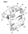
- FIG 4 an embodiment of a corresponding spindle slide is shown in partial view, which is designated there as a whole with 102.
- the spindle slide 102 corresponds for example to the first spindle slide 14.
- the spindle slide 102 has a first leg 104 and a second leg 106, wherein the second leg 106 is oriented transversely to the first leg 104.
- the spindle slide 102 has an L-shaped or triangular shape.
- the spindle slide 102 has a receptacle 108 for the associated workpiece spindle.
- the spindle slide 102 has a first guide shoe 110a and a second guide shoe 110b, which serve to guide the spindle slide 102 in the guide 50.
- the guide 50 includes, for example, a guide rail with a guide web, which extends in the direction of displacement X and thereby points upward.
- the guide shoes 110a and 110b each have a receptacle 112 for this guide bar; the guide rail is received by the receptacles 112.
- the guide rail and the receptacles 112 are adapted to each other so that a transverse movement between the guide shoes 110a, 110b and the guide bar is transversely locked to the displacement direction X substantially. This is achieved for example by a form-fitting adaptation of the receptacles 112 and the guide rail.
- the guide shoes 110a, 110b are seated on a holding element 114, which is held on a side wall 116 of the first leg 104.
- the guide shoe 118 On the second leg 106 sits another guide shoe 118, which is arranged in particular the second guide shoe 110b opposite. About this guide shoe 118 is provided for guiding the spindle carriage 102 at the spaced apart from the first guide 50 second guide 52. Accordingly, the guide shoe 118 is mounted on a guide rail of the second guide 52, as described in connection with the guide shoes 110a and 110b. Preferably, the guide shoe 118 is at the same vertical height as the guide shoes 110a and 110b.
- a guide device for guiding the carriage 102 on the machine tool according to the invention additionally comprises a support guide 120 (FIGS. 4 and 5).
- the support guide has a first guide device 122, which is arranged on the carriage 102, and a second guide device 124, which corresponds to the first guide device 122 and is arranged on the machine frame 12.
- the first guide device 122 is arranged on the first leg 104 and in particular its side wall 116. It includes, for example, two spaced guide shoes 126a and 126b. The first guide device 122 with its guide shoes 126a, 126b is arranged on the first leg 104 with respect to the Z direction above the guide shoes 110a, 110b for the guide 50.
- the guide shoes 126a, 126b each have a receptacle 128, in which engages a guide rail 130 of the second guide means 124 and in particular engages in such a form-fitting manner that a movement is locked transversely to the displacement direction X.
- the receptacle 128 is open to a direction which is transverse and in particular perpendicular to the direction in which the receptacles 112 of the guide shoes 110a, 110b are open.
- the second guide device 124 with its guide strip 130 can thereby dip laterally into the guide shoes 126a, 126b.
- the receptacle 128 has an extension along the displacement direction X.
- the guide rail 130 also has an extension in this direction of displacement, wherein the guide rail 130 is formed continuously. It sits above a bracket 132 ( Figure 5) stationary relative to the machine frame 12 relative to the Z-direction above the guides 50 and 52nd
- a corresponding element of a linear motor is seated on the leg 104.
- a stator (primary part) 134 is seated on the leg 104.
- a holding frame 136 which in turn is fixed to the side wall 116 of the first leg 104, is provided for fixing the primary part.
- a linear motor 140 is formed by a secondary part 138, which may comprise a plurality of secondary elements, and the primary part 134.
- the secondary part 138 is then arranged on the bracket 132 opposite the primary part 134 and facing this.
- stator 134 is seated on the bracket 132 and the secondary part is seated on the carriage 102 (long stator linear motor).
- the support guide 120 can absorb the forces caused by the linear motor 140, so that a closed guide system for the carriage 102 is formed. Since the forces of the linear motor 140 act substantially transverse to the Z direction, the images 128 of the Guide shoes 126a, 126b also open transversely to the Z direction.
- the support guide 120 is vertically spaced from the first guide 50 and the second guide 52.
- This second spindle slide (not shown in the drawing) is basically the same design as the spindle slide 102 described above, but it is adapted in its L-shaped or triangular configuration so that it corresponds to the spindle slide 102, that is formed such mirror-symmetrical in that its first leg, which has the larger guide surface, is spaced parallel to the first leg 104 of the spindle slide 102, and its second leg, on which the single guide shoe is seated, is parallel spaced from the second leg 106 of the spindle slide 102.
Claims (32)
- Machine-outil multibroche comprenant un bâti de machine (12), un premier chariot porte-broche (14) comportant une première broche porte-pièce (16), et un deuxième chariot porte-broche (18) comportant une deuxième broche porte-pièce (20), où le premier chariot porte-broche (14) et le deuxième chariot porte-broche (18) sont guidés en étant mobiles de façon linéaire sur le bâti de machine (12), comprenant un premier guidage (50) et un deuxième guidage (52) espacés, qui sont disposés sur le bâti de machine (12), où la première broche porte-pièce (16) et la deuxième broche porte-pièce (20) sont disposées entre les deux guidages (50, 52), et comprenant un dispositif de fixation d'outil (38), caractérisée en ce que aussi bien le premier chariot porte-broche (14) que le deuxième chariot porte-broche sont guidés sur le premier guidage (50) et sur le deuxième guidage (52), en ce que le premier chariot porte-broche (14) présente une première branche (54) qui est orientée le long du premier guidage (50), et présente une deuxième branche (58) qui est orientée de façon transversale par rapport au premier guidage (50), où la deuxième branche (58) du premier chariot porte-broche (14) est couplée au deuxième guidage (52), et en ce que le deuxième chariot porte-broche (18) présente une première branche (62) qui est orientée le long du deuxième guidage (52), et présente une deuxième branche (66) qui est orientée de façon transversale par rapport au deuxième guidage (52), où la deuxième branche (66) du deuxième chariot porte-broche (18) est couplée au premier guidage (50).
- Machine-outil multibroche selon la revendication 1, caractérisée en ce que le premier chariot porte-broche (14) et le deuxième chariot porte-broche (18) sont mécaniquement non accouplés.
- Machine-outil multibroche selon la revendication 1 ou 2, caractérisée en ce que le premier chariot porte-broche (14) présente une surface de contact avec le premier guidage (50), plus grande que celle avec le deuxième guidage (52).
- Machine-outil multibroche selon la revendication 3, caractérisée en ce que le premier chariot porte-broche (14) présente un plus grand nombre de patins de guidage (56a, 56b ; 60) pour le premier guidage (50) que pour le deuxième guidage (52).
- Machine-outil multibroche selon l'une quelconque des revendications précédentes, caractérisée en ce que le deuxième chariot porte-broche (18) présente une surface de contact avec le deuxième guidage (52), plus grande que celle avec le premier guidage (50).
- Machine-outil multibroche selon la revendication 5, caractérisée en ce que le deuxième chariot porte-broche (18) présente un plus grand nombre de patins de guidage (64a, 64b ; 68) pour le deuxième guidage (52) que pour le premier guidage (50).
- Machine-outil multibroche selon l'une quelconque des revendications précédentes, caractérisée en ce que le premier chariot porte-broche (14), au moins à proximité des guidages (50, 52), est en forme de L ou en forme de triangle.
- Machine-outil multibroche selon l'une quelconque des revendications précédentes, caractérisée en ce que la première broche porte-pièce (16) est placée entre et/ou sur les deux branches (54, 58).
- Machine-outil multibroche selon l'une quelconque des revendications précédentes, caractérisée en ce que le deuxième chariot porte-broche (18), au moins à proximité des guidages (50, 52), est en forme de L ou une forme de triangle.
- Machine-outil multibroche selon l'une quelconque des revendications précédentes, caractérisée en ce que la deuxième broche porte-pièce (20) est placée entre et/ou sur la première branche (62) et sur la deuxième branche (66).
- Machine-outil multibroche selon l'une quelconque des revendications précédentes, caractérisée en ce que les deuxièmes branches (58 ; 66) du premier chariot porte-broche (14) et du deuxième chariot porte-broche (18) sont parallèles entre elles.
- Machine-outil multibroche selon l'une quelconque des revendications précédentes, caractérisée en ce que les deux guidages (50, 52) sont parallèles entre eux.
- Machine-outil multibroche selon l'une quelconque des revendications précédentes, caractérisée en ce que les guidages comprennent des rails de guidage (50, 52).
- Machine-outil multibroche selon l'une quelconque des revendications précédentes, caractérisée en ce que la première broche porte-pièce (16) et la deuxième broche porte-pièce (20) sont tenues sur le chariot porte-broche associé (14 ; 18), en étant respectivement mobiles de façon linéaire dans une direction de déplacement (Z).
- Machine-outil multibroche selon la revendication 14, caractérisée en ce que la direction de déplacement (Z) d'une broche porte-pièce (16 ; 20) est orientée transversalement par rapport à une direction de déplacement (X) du chariot porte-broche associé (14 ; 18).
- Machine-outil multibroche selon l'une quelconque des revendications précédentes, caractérisée en ce que le premier guidage (50) et le deuxième guidage (52) sont disposés sur le bâti (12) de la machine, en étant orientés horizontalement.
- Machine-outil multibroche selon l'une quelconque des revendications précédentes, caractérisée en ce que les broches porte-pièces (16 ; 20) sont guidées verticalement sur le chariot porte-broche associé (14 ; 18).
- Machine-outil multibroche selon l'une quelconque des revendications précédentes, caractérisée en ce que le dispositif de fixation d'outil (38) présente une première fixation d'outil (42) et une deuxième fixation d'outil (44).
- Machine-outil multibroche selon la revendication 18, caractérisée en ce que les deux fixations d'outils (42, 44) sont disposées entre les deux guidages (50, 52).
- Machine-outil multibroche selon la revendication 18 ou 19, caractérisée en ce que les deux fixations d'outils (42, 44) sont disposées sur une coulisse (46).
- Machine-outil multibroche selon l'une quelconque des revendications précédentes, caractérisée en ce que le dispositif de fixation d'outil (38) est disposé de façon pivotante sur le bâti (12) de la machine.
- Machine-outil multibroche selon l'une quelconque des revendications précédentes, caractérisée en ce que les deux chariots porte-broches (14 ; 18) sont commandés en étant mobiles, de façon synchronisée l'un par rapport à l'autre ou bien de façon indépendante l'un de l'autre.
- Machine-outil multibroche selon l'une quelconque des revendications précédentes, caractérisée en ce que les deux broches porte-pièces (16 ; 20) sont commandées en étant mobiles, de façon synchronisée l'une par rapport à l'autre ou bien de façon indépendante l'une de l'autre.
- Machine-outil multibroche selon l'une quelconque des revendications précédentes, caractérisée en ce qu'une pièce à usiner est tenue, en rotation, sur une broche porte-pièce (16 ; 20) pour l'usinage par tournage.
- Machine-outil multibroche selon l'une quelconque des revendications précédentes, caractérisée en ce qu'il est prévu un guidage d'appui (120) pour le premier chariot porte-broche (102) et/ou pour le deuxième chariot porte-broche.
- Machine-outil multibroche selon la revendication 25, caractérisée en ce que le guidage d'appui (120) est disposé et configuré de manière telle, que des forces exercées par un moteur linéaire (140) puissent être absorbées.
- Machine-outil multibroche selon la revendication 26, caractérisée en ce que des forces horizontales et verticales peuvent être absorbées par le guidage d'appui (120).
- Machine-outil multibroche selon l'une quelconque des revendications 25 à 27, caractérisée en ce que le guidage d'appui (120) est disposé au-dessus du premier guidage (50) et du deuxième guidage (52) prévus pour les chariots porte-broches (102).
- Machine-outil multibroche selon l'une quelconque des revendications 25 à 28, caractérisée en ce que le guidage d'appui (120) comprend un premier dispositif de guidage (122) qui, en s'étendant dans la direction de déplacement, est disposé sur le chariot porte-broche associé (102), et comprend un deuxième dispositif de guidage correspondant (124) qui est disposé sur le bâti (12) de la machine.
- Machine-outil multibroche selon l'une quelconque des revendications 25 à 29, caractérisée en ce qu'un moteur linéaire (140), prévu pour le chariot porte-broche associé (102), est placé entre le guidage d'appui (120) et le premier guidage (50).
- Machine-outil multibroche selon l'une quelconque des revendications 25 à 30, caractérisée en ce qu'un moteur linéaire prévu pour le chariot porte-broche associé est placé entre le guidage d'appui (120) et le deuxième guidage (52).
- Machine-outil multibroche selon l'une quelconque des revendications 29 à 31, caractérisée en ce que le premier dispositif de guidage (122) est placé sur une paroi latérale (116) du chariot porte-broche associé (102).
Applications Claiming Priority (3)
| Application Number | Priority Date | Filing Date | Title |
|---|---|---|---|
| DE10235873 | 2002-07-30 | ||
| DE10235873A DE10235873A1 (de) | 2002-07-30 | 2002-07-30 | Mehrspindel-Werkzeugmaschine |
| PCT/EP2003/008101 WO2004012888A1 (fr) | 2002-07-30 | 2003-07-24 | Machine-outil dotee de deux broches porte-pieces |
Publications (2)
| Publication Number | Publication Date |
|---|---|
| EP1525065A1 EP1525065A1 (fr) | 2005-04-27 |
| EP1525065B1 true EP1525065B1 (fr) | 2007-05-02 |
Family
ID=30775026
Family Applications (1)
| Application Number | Title | Priority Date | Filing Date |
|---|---|---|---|
| EP03766271A Expired - Lifetime EP1525065B1 (fr) | 2002-07-30 | 2003-07-24 | Machine-outil dotee de deux broches porte-pieces |
Country Status (7)
| Country | Link |
|---|---|
| US (1) | US7124666B2 (fr) |
| EP (1) | EP1525065B1 (fr) |
| AT (1) | ATE361168T1 (fr) |
| AU (1) | AU2003250158A1 (fr) |
| DE (2) | DE10235873A1 (fr) |
| ES (1) | ES2285194T3 (fr) |
| WO (1) | WO2004012888A1 (fr) |
Cited By (1)
| Publication number | Priority date | Publication date | Assignee | Title |
|---|---|---|---|---|
| US10864611B2 (en) | 2017-05-12 | 2020-12-15 | Utitec, Inc. | Method of sharpening hardened thin metal blades |
Families Citing this family (18)
| Publication number | Priority date | Publication date | Assignee | Title |
|---|---|---|---|---|
| DE10333051A1 (de) * | 2003-07-18 | 2005-02-03 | Grob-Werke Burkhart Grob E.K. | Spanabhebende Bearbeitungsmaschine |
| DE102004008872A1 (de) * | 2004-02-18 | 2005-09-08 | Ex-Cell-O Gmbh | Verfahren zur Profilherstellung, insbesondere von Profilbahnen für Gelenkteile |
| JP4427689B2 (ja) * | 2004-07-08 | 2010-03-10 | オークマ株式会社 | 工作機械 |
| DE102004050035A1 (de) | 2004-07-09 | 2006-01-26 | Ex-Cell-O Gmbh | Werkzeugmaschine und Verfahren zum Werkzeugwechsel an einer Werkzeugmaschine |
| US7270592B2 (en) | 2004-08-12 | 2007-09-18 | D4D Technologies, Llc | Milling machine |
| DE102004058891B4 (de) * | 2004-11-30 | 2007-02-22 | Tfd Teilefertigung Dresden Gmbh | Präzisionswerkzeugmaschine mit zwei Arbeitsspindeln |
| DE102005039818A1 (de) * | 2005-08-22 | 2007-03-01 | Emag Holding Gmbh | Werkzeugmaschine mit schwenkbarer Werkzeugspindel |
| US20070267103A1 (en) * | 2006-05-18 | 2007-11-22 | Unique Machine And Tool Co. | Woodworking machine |
| DE102007043746B4 (de) | 2007-09-04 | 2017-10-26 | Mag Ias Gmbh | Fertigungsverfahren für einen Kugelkäfig eines Gelenks |
| DE102008058161A1 (de) | 2008-11-12 | 2010-05-20 | Ex-Cell-O Gmbh | Werkzeugmaschine mit schwimmend gelagerter Trägereinrichtung |
| DE102009048757A1 (de) * | 2009-10-08 | 2011-04-14 | Satisloh Ag | Vorrichtung zur Feinbearbeitung von optisch wirksamen Flächen an Werkstücken, insbesondere Brillengläsern |
| DE102010051284B4 (de) * | 2010-11-12 | 2014-11-20 | Mag Ias Gmbh | Verfahren und Werkzeugmaschine zum Herstellen von schrägstehenden Nuten in der Außen- oder Innenumfangsfläche eines rotationssymmetrischen Grundkörpers |
| DE102011101974B4 (de) * | 2011-05-19 | 2013-12-05 | Gildemeister Drehmaschinen Gmbh | Vertikaldrehmaschine |
| CN103567462A (zh) * | 2012-07-20 | 2014-02-12 | 鸿准精密模具(昆山)有限公司 | 车床 |
| DE102013004901A1 (de) * | 2013-03-21 | 2014-09-25 | Emag Holding Gmbh | Doppelspindlige Werkzeugmaschine |
| EP3050653B1 (fr) | 2015-01-29 | 2018-05-30 | Gildemeister Drehmaschinen GmbH | Tour vertical doté de porte-outil pivotant et de tourelle revolver |
| DE102015102899B4 (de) | 2015-02-27 | 2018-02-01 | Optotech Optikmaschinen Gmbh | Fräsvorrichtung für die Brillenglasfertigung mit zwei Frässtationen |
| DE102019002054A1 (de) * | 2019-03-22 | 2020-09-24 | Vollmer Werke Maschinenfabrik Gmbh | Vorrichtung und Verfahren zum Bearbeiten von gleichartigen Werkstücken |
Family Cites Families (13)
| Publication number | Priority date | Publication date | Assignee | Title |
|---|---|---|---|---|
| US4197769A (en) | 1978-05-05 | 1980-04-15 | The Motch & Merryweather Machinery Company | Dual spindle NC chucking/turning machine |
| FR2590340B1 (fr) * | 1985-11-18 | 1989-11-17 | Dejoux Andre | Dispositif de guidage et d'entrainement d'organes mecaniques mobiles a deplacement lineaire |
| DE8700343U1 (fr) | 1987-01-08 | 1988-05-11 | Mauser-Werke Oberndorf Gmbh, 7238 Oberndorf, De | |
| DE8711148U1 (fr) | 1987-08-17 | 1987-10-29 | Gebrueder Brinkmann Gmbh, Maschinen- Und Zahnraederfabrik, 4930 Detmold, De | |
| SE8804305L (sv) * | 1988-11-28 | 1990-05-29 | Fredrik Bror Bengt Lagercrantz | Anordning foer att kunna inreglera en robotbalks fria aende mot ett paa foerhand bestaemt positionslaege |
| DE4136916C3 (de) * | 1991-11-11 | 1997-03-13 | Pittler Gmbh | Mehrspindel-Drehmaschine |
| US5704262A (en) | 1991-11-11 | 1998-01-06 | Pcc Pittler Maschinenfabrik Gmbh | Multiple-spindle lathe |
| DE19514058C2 (de) * | 1995-04-13 | 1998-04-30 | Emag Masch Vertriebs Serv Gmbh | Drehmaschine mit mehreren Spindeln |
| DE19516774A1 (de) | 1995-05-10 | 1996-11-21 | Brinkmann Masch & Zahnradfab | Numerisch gesteuerte Zweispindel-Drehmaschine |
| US5920973A (en) * | 1997-03-09 | 1999-07-13 | Electro Scientific Industries, Inc. | Hole forming system with multiple spindles per station |
| FR2801823B1 (fr) | 1999-09-07 | 2002-02-15 | Renault Automation Comau | Machine-outil d'usinage de type bibroche |
| DE19945567C2 (de) * | 1999-09-23 | 2001-12-06 | Esab Hancock Gmbh | Portal einer Portalschneidmaschine |
| DE19963863B4 (de) * | 1999-12-30 | 2006-01-12 | Tfd Teilefertigung Dresden Gmbh | Bearbeitungsanlage für die spanende Bearbeitung von Freiformflächen an Werkstücken des Formen-, Gesenk-, Vorrichtungs- und Modellbaus |
-
2002
- 2002-07-30 DE DE10235873A patent/DE10235873A1/de not_active Ceased
-
2003
- 2003-07-24 EP EP03766271A patent/EP1525065B1/fr not_active Expired - Lifetime
- 2003-07-24 DE DE50307181T patent/DE50307181D1/de not_active Expired - Lifetime
- 2003-07-24 ES ES03766271T patent/ES2285194T3/es not_active Expired - Lifetime
- 2003-07-24 AU AU2003250158A patent/AU2003250158A1/en not_active Abandoned
- 2003-07-24 AT AT03766271T patent/ATE361168T1/de active
- 2003-07-24 WO PCT/EP2003/008101 patent/WO2004012888A1/fr active IP Right Grant
-
2005
- 2005-01-05 US US11/029,283 patent/US7124666B2/en not_active Expired - Lifetime
Cited By (1)
| Publication number | Priority date | Publication date | Assignee | Title |
|---|---|---|---|---|
| US10864611B2 (en) | 2017-05-12 | 2020-12-15 | Utitec, Inc. | Method of sharpening hardened thin metal blades |
Also Published As
| Publication number | Publication date |
|---|---|
| WO2004012888A1 (fr) | 2004-02-12 |
| EP1525065A1 (fr) | 2005-04-27 |
| DE10235873A1 (de) | 2004-02-26 |
| DE50307181D1 (de) | 2007-06-14 |
| US7124666B2 (en) | 2006-10-24 |
| AU2003250158A1 (en) | 2004-02-23 |
| ES2285194T3 (es) | 2007-11-16 |
| US20050139048A1 (en) | 2005-06-30 |
| ATE361168T1 (de) | 2007-05-15 |
Similar Documents
| Publication | Publication Date | Title |
|---|---|---|
| EP1525065B1 (fr) | Machine-outil dotee de deux broches porte-pieces | |
| EP1188511B1 (fr) | Machine-outil avec un chariot porte-outil motorisé | |
| EP0712683B1 (fr) | Machine-outil, en particulier perceuse-fraiseuse | |
| EP1338376B1 (fr) | Fraiseuse pour fraisage et tournage de pièces en forme de barre | |
| EP2255907B1 (fr) | Machine-outil et procédé destiné au traitement par enlèvement de copeaux de pièces usinées, en particulier de pièces usinées métalliques | |
| EP0989923B1 (fr) | Machine outil a flexibilite elevee | |
| EP1645359B1 (fr) | Machine outil | |
| EP1418019B2 (fr) | Machine-outil avec au moins deux tourettes revolver à outils, comprenant chacune un dispositif porte-pièce | |
| EP0995539B1 (fr) | Dispositif d'usinage de pièces | |
| EP1718435B1 (fr) | Machine d'usinage pour usiner des pieces | |
| EP1027955B1 (fr) | Machine-outil | |
| EP0737544A2 (fr) | Machine-outil avec plusieurs broches | |
| EP1413395A1 (fr) | Machine-outil | |
| EP1409182A2 (fr) | Machine-outil | |
| DE102011056099B3 (de) | Werkzeugmaschine | |
| EP2762253A1 (fr) | Machine-outil destinée au traitement de pièces à usiner | |
| EP1074333B1 (fr) | Tour avec deux systèmes de support d'outils | |
| DE10144679A1 (de) | Bearbeitungszentrum | |
| DE10130760A1 (de) | Drehmaschine | |
| EP2995419B1 (fr) | Machine-outil | |
| EP3624988B1 (fr) | Machine-outil | |
| DE10145674B4 (de) | Werkzeugmaschine zur Bearbeitung eines stangenförmigen Werkstücks | |
| DE19607883A1 (de) | Vertikal-Drehmaschine | |
| EP0883456A1 (fr) | Machine-outil comportant plusieurs broches | |
| EP3144101A1 (fr) | Machine-outil comprenant un module de fonction |
Legal Events
| Date | Code | Title | Description |
|---|---|---|---|
| PUAI | Public reference made under article 153(3) epc to a published international application that has entered the european phase |
Free format text: ORIGINAL CODE: 0009012 |
|
| 17P | Request for examination filed |
Effective date: 20040709 |
|
| AK | Designated contracting states |
Kind code of ref document: A1 Designated state(s): AT BE BG CH CY CZ DE DK EE ES FI FR GB GR HU IE IT LI LU MC NL PT RO SE SI SK TR |
|
| AX | Request for extension of the european patent |
Extension state: AL LT LV MK |
|
| DAX | Request for extension of the european patent (deleted) | ||
| GRAP | Despatch of communication of intention to grant a patent |
Free format text: ORIGINAL CODE: EPIDOSNIGR1 |
|
| GRAS | Grant fee paid |
Free format text: ORIGINAL CODE: EPIDOSNIGR3 |
|
| GRAA | (expected) grant |
Free format text: ORIGINAL CODE: 0009210 |
|
| AK | Designated contracting states |
Kind code of ref document: B1 Designated state(s): AT BE BG CH CY CZ DE DK EE ES FI FR GB GR HU IE IT LI LU MC NL PT RO SE SI SK TR |
|
| PG25 | Lapsed in a contracting state [announced via postgrant information from national office to epo] |
Ref country code: FI Free format text: LAPSE BECAUSE OF FAILURE TO SUBMIT A TRANSLATION OF THE DESCRIPTION OR TO PAY THE FEE WITHIN THE PRESCRIBED TIME-LIMIT Effective date: 20070502 |
|
| REG | Reference to a national code |
Ref country code: GB Ref legal event code: FG4D Free format text: NOT ENGLISH |
|
| REG | Reference to a national code |
Ref country code: CH Ref legal event code: EP |
|
| REG | Reference to a national code |
Ref country code: IE Ref legal event code: FG4D Free format text: LANGUAGE OF EP DOCUMENT: GERMAN |
|
| REF | Corresponds to: |
Ref document number: 50307181 Country of ref document: DE Date of ref document: 20070614 Kind code of ref document: P |
|
| PG25 | Lapsed in a contracting state [announced via postgrant information from national office to epo] |
Ref country code: SE Free format text: LAPSE BECAUSE OF FAILURE TO SUBMIT A TRANSLATION OF THE DESCRIPTION OR TO PAY THE FEE WITHIN THE PRESCRIBED TIME-LIMIT Effective date: 20070802 |
|
| GBT | Gb: translation of ep patent filed (gb section 77(6)(a)/1977) |
Effective date: 20070731 |
|
| ET | Fr: translation filed | ||
| NLV1 | Nl: lapsed or annulled due to failure to fulfill the requirements of art. 29p and 29m of the patents act | ||
| REG | Reference to a national code |
Ref country code: ES Ref legal event code: FG2A Ref document number: 2285194 Country of ref document: ES Kind code of ref document: T3 |
|
| REG | Reference to a national code |
Ref country code: IE Ref legal event code: FD4D |
|
| BERE | Be: lapsed |
Owner name: EX-CELL-O G.M.B.H. Effective date: 20070731 |
|
| PG25 | Lapsed in a contracting state [announced via postgrant information from national office to epo] |
Ref country code: IE Free format text: LAPSE BECAUSE OF FAILURE TO SUBMIT A TRANSLATION OF THE DESCRIPTION OR TO PAY THE FEE WITHIN THE PRESCRIBED TIME-LIMIT Effective date: 20070502 Ref country code: DK Free format text: LAPSE BECAUSE OF FAILURE TO SUBMIT A TRANSLATION OF THE DESCRIPTION OR TO PAY THE FEE WITHIN THE PRESCRIBED TIME-LIMIT Effective date: 20070502 Ref country code: CZ Free format text: LAPSE BECAUSE OF FAILURE TO SUBMIT A TRANSLATION OF THE DESCRIPTION OR TO PAY THE FEE WITHIN THE PRESCRIBED TIME-LIMIT Effective date: 20070502 Ref country code: BG Free format text: LAPSE BECAUSE OF FAILURE TO SUBMIT A TRANSLATION OF THE DESCRIPTION OR TO PAY THE FEE WITHIN THE PRESCRIBED TIME-LIMIT Effective date: 20070802 Ref country code: PT Free format text: LAPSE BECAUSE OF FAILURE TO SUBMIT A TRANSLATION OF THE DESCRIPTION OR TO PAY THE FEE WITHIN THE PRESCRIBED TIME-LIMIT Effective date: 20071002 Ref country code: NL Free format text: LAPSE BECAUSE OF FAILURE TO SUBMIT A TRANSLATION OF THE DESCRIPTION OR TO PAY THE FEE WITHIN THE PRESCRIBED TIME-LIMIT Effective date: 20070502 Ref country code: SI Free format text: LAPSE BECAUSE OF FAILURE TO SUBMIT A TRANSLATION OF THE DESCRIPTION OR TO PAY THE FEE WITHIN THE PRESCRIBED TIME-LIMIT Effective date: 20070502 |
|
| PG25 | Lapsed in a contracting state [announced via postgrant information from national office to epo] |
Ref country code: SK Free format text: LAPSE BECAUSE OF FAILURE TO SUBMIT A TRANSLATION OF THE DESCRIPTION OR TO PAY THE FEE WITHIN THE PRESCRIBED TIME-LIMIT Effective date: 20070502 |
|
| PLBE | No opposition filed within time limit |
Free format text: ORIGINAL CODE: 0009261 |
|
| STAA | Information on the status of an ep patent application or granted ep patent |
Free format text: STATUS: NO OPPOSITION FILED WITHIN TIME LIMIT |
|
| REG | Reference to a national code |
Ref country code: CH Ref legal event code: PL |
|
| 26N | No opposition filed |
Effective date: 20080205 |
|
| PG25 | Lapsed in a contracting state [announced via postgrant information from national office to epo] |
Ref country code: CH Free format text: LAPSE BECAUSE OF NON-PAYMENT OF DUE FEES Effective date: 20070731 Ref country code: MC Free format text: LAPSE BECAUSE OF NON-PAYMENT OF DUE FEES Effective date: 20070731 Ref country code: GR Free format text: LAPSE BECAUSE OF FAILURE TO SUBMIT A TRANSLATION OF THE DESCRIPTION OR TO PAY THE FEE WITHIN THE PRESCRIBED TIME-LIMIT Effective date: 20070803 Ref country code: LI Free format text: LAPSE BECAUSE OF NON-PAYMENT OF DUE FEES Effective date: 20070731 |
|
| PG25 | Lapsed in a contracting state [announced via postgrant information from national office to epo] |
Ref country code: RO Free format text: LAPSE BECAUSE OF FAILURE TO SUBMIT A TRANSLATION OF THE DESCRIPTION OR TO PAY THE FEE WITHIN THE PRESCRIBED TIME-LIMIT Effective date: 20070502 |
|
| PG25 | Lapsed in a contracting state [announced via postgrant information from national office to epo] |
Ref country code: BE Free format text: LAPSE BECAUSE OF NON-PAYMENT OF DUE FEES Effective date: 20070731 |
|
| PG25 | Lapsed in a contracting state [announced via postgrant information from national office to epo] |
Ref country code: EE Free format text: LAPSE BECAUSE OF FAILURE TO SUBMIT A TRANSLATION OF THE DESCRIPTION OR TO PAY THE FEE WITHIN THE PRESCRIBED TIME-LIMIT Effective date: 20070502 |
|
| PG25 | Lapsed in a contracting state [announced via postgrant information from national office to epo] |
Ref country code: CY Free format text: LAPSE BECAUSE OF FAILURE TO SUBMIT A TRANSLATION OF THE DESCRIPTION OR TO PAY THE FEE WITHIN THE PRESCRIBED TIME-LIMIT Effective date: 20070502 |
|
| PG25 | Lapsed in a contracting state [announced via postgrant information from national office to epo] |
Ref country code: LU Free format text: LAPSE BECAUSE OF NON-PAYMENT OF DUE FEES Effective date: 20070724 |
|
| PG25 | Lapsed in a contracting state [announced via postgrant information from national office to epo] |
Ref country code: TR Free format text: LAPSE BECAUSE OF FAILURE TO SUBMIT A TRANSLATION OF THE DESCRIPTION OR TO PAY THE FEE WITHIN THE PRESCRIBED TIME-LIMIT Effective date: 20070502 Ref country code: HU Free format text: LAPSE BECAUSE OF FAILURE TO SUBMIT A TRANSLATION OF THE DESCRIPTION OR TO PAY THE FEE WITHIN THE PRESCRIBED TIME-LIMIT Effective date: 20071103 |
|
| PGFP | Annual fee paid to national office [announced via postgrant information from national office to epo] |
Ref country code: AT Payment date: 20110628 Year of fee payment: 9 |
|
| REG | Reference to a national code |
Ref country code: AT Ref legal event code: MM01 Ref document number: 361168 Country of ref document: AT Kind code of ref document: T Effective date: 20120724 |
|
| PG25 | Lapsed in a contracting state [announced via postgrant information from national office to epo] |
Ref country code: AT Free format text: LAPSE BECAUSE OF NON-PAYMENT OF DUE FEES Effective date: 20120724 |
|
| REG | Reference to a national code |
Ref country code: DE Ref legal event code: R082 Ref document number: 50307181 Country of ref document: DE Representative=s name: HOEGER, STELLRECHT & PARTNER PATENTANWAELTE MB, DE |
|
| REG | Reference to a national code |
Ref country code: FR Ref legal event code: PLFP Year of fee payment: 14 |
|
| REG | Reference to a national code |
Ref country code: FR Ref legal event code: PLFP Year of fee payment: 15 |
|
| REG | Reference to a national code |
Ref country code: FR Ref legal event code: PLFP Year of fee payment: 16 |
|
| PGFP | Annual fee paid to national office [announced via postgrant information from national office to epo] |
Ref country code: FR Payment date: 20180723 Year of fee payment: 16 |
|
| PGFP | Annual fee paid to national office [announced via postgrant information from national office to epo] |
Ref country code: GB Payment date: 20180725 Year of fee payment: 16 |
|
| REG | Reference to a national code |
Ref country code: DE Ref legal event code: R082 Ref document number: 50307181 Country of ref document: DE Representative=s name: HOEGER, STELLRECHT & PARTNER PATENTANWAELTE MB, DE |
|
| GBPC | Gb: european patent ceased through non-payment of renewal fee |
Effective date: 20190724 |
|
| PG25 | Lapsed in a contracting state [announced via postgrant information from national office to epo] |
Ref country code: GB Free format text: LAPSE BECAUSE OF NON-PAYMENT OF DUE FEES Effective date: 20190724 |
|
| PG25 | Lapsed in a contracting state [announced via postgrant information from national office to epo] |
Ref country code: FR Free format text: LAPSE BECAUSE OF NON-PAYMENT OF DUE FEES Effective date: 20190731 |
|
| REG | Reference to a national code |
Ref country code: ES Ref legal event code: FD2A Effective date: 20201202 |
|
| PG25 | Lapsed in a contracting state [announced via postgrant information from national office to epo] |
Ref country code: ES Free format text: LAPSE BECAUSE OF NON-PAYMENT OF DUE FEES Effective date: 20190725 |
|
| PGFP | Annual fee paid to national office [announced via postgrant information from national office to epo] |
Ref country code: IT Payment date: 20220729 Year of fee payment: 20 Ref country code: DE Payment date: 20220621 Year of fee payment: 20 |
|
| REG | Reference to a national code |
Ref country code: DE Ref legal event code: R071 Ref document number: 50307181 Country of ref document: DE |