EP1057376B1 - Concept de circuit - Google Patents
Concept de circuit Download PDFInfo
- Publication number
- EP1057376B1 EP1057376B1 EP99959373A EP99959373A EP1057376B1 EP 1057376 B1 EP1057376 B1 EP 1057376B1 EP 99959373 A EP99959373 A EP 99959373A EP 99959373 A EP99959373 A EP 99959373A EP 1057376 B1 EP1057376 B1 EP 1057376B1
- Authority
- EP
- European Patent Office
- Prior art keywords
- lamp
- current
- circuit arrangement
- parameter
- voltage
- Prior art date
- Legal status (The legal status is an assumption and is not a legal conclusion. Google has not performed a legal analysis and makes no representation as to the accuracy of the status listed.)
- Expired - Lifetime
Links
Images


Classifications
-
- H—ELECTRICITY
- H05—ELECTRIC TECHNIQUES NOT OTHERWISE PROVIDED FOR
- H05B—ELECTRIC HEATING; ELECTRIC LIGHT SOURCES NOT OTHERWISE PROVIDED FOR; CIRCUIT ARRANGEMENTS FOR ELECTRIC LIGHT SOURCES, IN GENERAL
- H05B41/00—Circuit arrangements or apparatus for igniting or operating discharge lamps
- H05B41/14—Circuit arrangements
- H05B41/26—Circuit arrangements in which the lamp is fed by power derived from dc by means of a converter, e.g. by high-voltage dc
- H05B41/28—Circuit arrangements in which the lamp is fed by power derived from dc by means of a converter, e.g. by high-voltage dc using static converters
- H05B41/288—Circuit arrangements in which the lamp is fed by power derived from dc by means of a converter, e.g. by high-voltage dc using static converters with semiconductor devices and specially adapted for lamps without preheating electrodes, e.g. for high-intensity discharge lamps, high-pressure mercury or sodium lamps or low-pressure sodium lamps
- H05B41/292—Arrangements for protecting lamps or circuits against abnormal operating conditions
- H05B41/2928—Arrangements for protecting lamps or circuits against abnormal operating conditions for protecting the lamp against abnormal operating conditions
-
- Y—GENERAL TAGGING OF NEW TECHNOLOGICAL DEVELOPMENTS; GENERAL TAGGING OF CROSS-SECTIONAL TECHNOLOGIES SPANNING OVER SEVERAL SECTIONS OF THE IPC; TECHNICAL SUBJECTS COVERED BY FORMER USPC CROSS-REFERENCE ART COLLECTIONS [XRACs] AND DIGESTS
- Y10—TECHNICAL SUBJECTS COVERED BY FORMER USPC
- Y10S—TECHNICAL SUBJECTS COVERED BY FORMER USPC CROSS-REFERENCE ART COLLECTIONS [XRACs] AND DIGESTS
- Y10S315/00—Electric lamp and discharge devices: systems
- Y10S315/05—Starting and operating circuit for fluorescent lamp
Definitions
- the invention relates to a circuit arrangement for operating a high pressure discharge lamp with a current having successive periods of opposite polarity, which lamp is provided with at least two main electrodes being placed at a certain distance from each other, the circuit arrangement comprising:
- Such a circuit arrangement is known from the American Patent 5,608,294.
- the known circuit arrangement provides a measure to suppers flickering of a high pressure discharge lamp and is in particular suitable for operating a high pressure discharge lamp in a projection system like a projection television apparatus.
- the lamp is supplied with a current of successive block shaped periods of opposite polarity.
- the suppression of flickering is reached by supplying to periods of the lamp current an additional current pulses with the same polarity at the end of a predetermined fraction of such a period of the lamp current.
- the temperature of the electrode is raised to a relatively high value, which high temperature increases the stability of the discharge arc, because the discharge arc originates from the same place on the electrode in each cathodic phase and so flickering is substantially suppressed.
- the additional current is supplied in a regular sequence, preferably at each successive pulse.
- each electrode of the lamp alternatingly functions as a cathode and as an anode during successive periods of the lamp current. During these periods the electrode is said to be in the cathodic phase and the anodic phase respectively. Electrode material, that is removed from the electrode in the anodic phase, returns to the electrode as a stream of ions in the cathodic phase.
- the invention aims to provide a circuit arrangement for operating a high pressure discharge lamp in a way which substantially overcomes the mentioned drawback and simultaneously is maintaining the substantially suppression of flickering of the lamp during its operation.
- a circuit arrangement of the kind mentioned in the opening paragraph is for this purpose characterized in that that the circuit arrangement is provided with
- circuit arrangement further comprises:
- the first parameter is formed by the lamp voltage, preferable averaged over several periods.
- the lamp voltage during each successive period is providing for the second parameter.
- Use of the lamp voltage for forming the second parameter has as advantage that for first and second parameter the same quantity is used. This simplifies the circuit arrangement.
- the shape of the lamp voltage during each period is detected and used for forming the second parameter. Preferable this is realized by means in the circuit arrangement which measure the lamp voltage at selected intervals during such a period and compare the thus found values with each other.
- the second parameter is formed by the luminous output of the lamp, for instance by means of optical detectors placed around a display area of a projection system, for instance at the edge of the display area.
- the operation of the circuit arrangement shown in Fig. 2 with the converter being a Buck or down converter is as follows.
- the microcontroller MC is provided with software for prosecution procedures as further explained herebelow with reference to figures 3 and 4.
- the procedures result in a converter peak current value which is fed to switching circuit SC at input 4 and used as reference for comparison for the detected current at input 2 which is also fed to the switching circuit SC, at input 5.
- the switching circuit Based on this current values comparison the switching circuit generates a switching off signal at output O, which switches the switch of the down converter in the non- conducting state when the detected current equals the peak current value.
- the current through the inductive means will decrease.
- the converter switch is kept in the non-conductive state until the current through the inductive means L becomes zero.
- This mode provides for flicker free operation and also for growth of the electrode tips and so reduction of the electrode distance.
- This mode provides for flicker free operation and also for growth of the electrode tips and so reduction of the electrode distance.
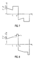
- the resulting current is shown in fig 7.
- the current I1 at the start of the period is higher than Ie.
- fig 8 is shown a graph of the current according to another mode of operation in which the lamp current is provided with a pulse of the same polarity at the end of the period with a value I3.
- the requirements 1.4 ⁇ I3/Im ⁇ 4 and .02 ⁇ t3/tp ⁇ .25 should be fulfilled, in which t3 is the pulse width.
- the value of I3 is 1.6Im. From experiments it has been deduced that I3 is preferable chosen in the range 1.6 ⁇ I3/Im ⁇ 3.
- a current shape as shown in fig 10 in which an additional current pulse of opposite polarity is applied, is also suitable for causing lamp voltage increase.
- the current shape is effective for lamp voltage increase.
- FIG. 1 A practical embodiment of a circuit arrangement as shown in Fig. 1 has been used for the operation of a high pressure discharge lamp of the type UHP, make Philips.
- the lamp had a nominal power consumption of 100 Watt and an electrode distance of only 1.4 mm, was operated with two different modes of operation defining different shapes of successive periods forming the lamp current.
- a first mode of operation the successive periods of opposite polarity are shaped as shown in fig 9.
- the value of the current in this mode corresponding to I1 is regulated by way of a wattage control incorporated in the microcontroller software to a nominal value of 1.06A.
- the maximum value for I3 is fixed at 2.5A.
- the lamp voltage having a nominal value of 85V
- the current I3 is fixed at 2.5A.
- the periods are reshaped by the means A in that the current I3 is stepped down in 3 steps to the value of II, after which the means A switch over to a second mode of operation in which the supplied lamp current is formed by periods which are shaped as rectangular blocks with a value controlled with the same wattage control as mentioned for the first mode at the same nominal value as I1.
- the voltage minimum level U- is 68V.
- a value of 110V is used.
- microcontroller MC a P87C749EBP, make Philips has shown to be suitable when programmed to detect the lamp voltage once at a fixed moment during each period, preferably at 0.75tp.
Landscapes
- Circuit Arrangements For Discharge Lamps (AREA)
- Lock And Its Accessories (AREA)
- Selective Calling Equipment (AREA)
- Inductance-Capacitance Distribution Constants And Capacitance-Resistance Oscillators (AREA)
Claims (7)
- Montage de circuit pour faire fonctionner une lampe à décharge à haute pression (LA) avec un courant ayant des périodes successives de polarité opposée, laquelle lampe est pourvue d'au moins deux électrodes principales l'une étant positionnée à une certaine distance espacée de l'autre, le montage de circuit comprenant:caractérisé en ce que le montage de circuit est pourvu dedes bornes d'entrée (K1, K2) pour connecter une source d'alimentation,des bornes de sortie (L1, L2) pour connecter la lampe à décharge à haute pression (LA), etdes moyens (II) qui sont couplés aux bornes d'entrée (K1, K2) pour fournir le courant de lampe à la lampe à décharge à haute pression (LA) dont les périodes successives présentent une forme prédéterminée,moyens (MC) pour détecter un premier paramètre qui est indicatif de la distance comprise entre les électrodes et pour former un premier signal qui est dépendant du premier paramètre, et demoyens (III) pour réorganiser les périodes du courant de lampe dépendamment du premier signal ainsi formé.
- Montage de circuit selon la revendication 1, dans lequel le montage de circuit comprend encore:des moyens (MC) pour détecter un second paramètre qui est indicatif de l'apparition du scintillement de la lampe et pour former un second signal qui est dépendant du second paramètre détecté, etdes moyens (III) pour un nouveau autre ajustage de la forme des périodes successives dépendamment du second signal ainsi formé.
- Montage de circuit selon la revendication 1 ou 2, caractérisé en ce que le premier paramètre est constitué par la tension de lampe.
- Montage de circuit selon la revendication 1, 2 ou 3, caractérisé en ce que le second paramètre est constitué par la tension de lampe pendant des périodes de courant successives.
- Montage de circuit selon la revendication 4, caractérisé en ce que la tension de lampe pendant chaque période présente une forme qui est détectée.
- Montage de circuit selon la revendication 4, caractérisé en ce que la tension de lampe pendant chaque période présente une valeur qui est détectée.
- Montage de circuit selon la revendication 1, 2 ou 3, caractérisé en ce que le second paramètre est constitué par le flux lumineux de la lampe.
Priority Applications (1)
| Application Number | Priority Date | Filing Date | Title |
|---|---|---|---|
| EP99959373A EP1057376B1 (fr) | 1998-12-17 | 1999-12-01 | Concept de circuit |
Applications Claiming Priority (4)
| Application Number | Priority Date | Filing Date | Title |
|---|---|---|---|
| EP98204288 | 1998-12-17 | ||
| EP98204288 | 1998-12-17 | ||
| PCT/EP1999/009352 WO2000036882A1 (fr) | 1998-12-17 | 1999-12-01 | Concept de circuit |
| EP99959373A EP1057376B1 (fr) | 1998-12-17 | 1999-12-01 | Concept de circuit |
Publications (2)
| Publication Number | Publication Date |
|---|---|
| EP1057376A1 EP1057376A1 (fr) | 2000-12-06 |
| EP1057376B1 true EP1057376B1 (fr) | 2003-10-15 |
Family
ID=8234478
Family Applications (1)
| Application Number | Title | Priority Date | Filing Date |
|---|---|---|---|
| EP99959373A Expired - Lifetime EP1057376B1 (fr) | 1998-12-17 | 1999-12-01 | Concept de circuit |
Country Status (9)
| Country | Link |
|---|---|
| US (1) | US6232725B1 (fr) |
| EP (1) | EP1057376B1 (fr) |
| JP (1) | JP4508425B2 (fr) |
| KR (1) | KR100664337B1 (fr) |
| CN (1) | CN1155300C (fr) |
| AT (1) | ATE252309T1 (fr) |
| DE (1) | DE69912102T2 (fr) |
| TW (1) | TW490998B (fr) |
| WO (1) | WO2000036882A1 (fr) |
Cited By (1)
| Publication number | Priority date | Publication date | Assignee | Title |
|---|---|---|---|---|
| WO2005062684A1 (fr) * | 2003-12-19 | 2005-07-07 | Philips Intellectual Property & Standards Gmbh | Methode et agencement de circuits d'exploitation d'une lampe a decharge |
Families Citing this family (39)
| Publication number | Priority date | Publication date | Assignee | Title |
|---|---|---|---|---|
| JP4426132B2 (ja) * | 2000-07-26 | 2010-03-03 | ハリソン東芝ライティング株式会社 | 高圧放電ランプ点灯方法、高圧放電ランプ点灯装置および照明装置 |
| TW512376B (en) | 2000-08-17 | 2002-12-01 | Koninkl Philips Electronics Nv | Switching device |
| JP2002134287A (ja) | 2000-10-24 | 2002-05-10 | Tdk Corp | 放電灯点灯方法及び装置 |
| DE10062974A1 (de) * | 2000-12-16 | 2002-06-20 | Philips Corp Intellectual Pty | Hochdruckgasentladungslampe und Verfahren zu ihrer Herstellung |
| US6476566B2 (en) | 2000-12-27 | 2002-11-05 | Infocus Systems, Inc. | Method and apparatus for canceling ripple current in a lamp |
| US6407623B1 (en) * | 2001-01-31 | 2002-06-18 | Qualcomm Incorporated | Bias circuit for maintaining a constant value of transconductance divided by load capacitance |
| ATE392796T1 (de) * | 2002-06-25 | 2008-05-15 | Koninkl Philips Electronics Nv | Betrieb einer entladungslampe |
| JP4186578B2 (ja) * | 2002-10-09 | 2008-11-26 | ウシオ電機株式会社 | 高圧放電ランプ点灯装置 |
| CN1954646B (zh) * | 2004-02-02 | 2010-09-08 | 岩崎电气株式会社 | 高压放电灯点灯装置及点灯方法 |
| EP2146553B1 (fr) | 2004-02-24 | 2019-01-02 | Panasonic Intellectual Property Management Co., Ltd. | Ballaste de lampe à décharge et projecteur |
| DE102004020397A1 (de) * | 2004-04-23 | 2005-11-10 | Patent-Treuhand-Gesellschaft für elektrische Glühlampen mbH | Verfahren zum Betreiben einer Hochdruckentladungslampe |
| JP4241515B2 (ja) | 2004-06-10 | 2009-03-18 | パナソニック電工株式会社 | 放電灯点灯装置及びプロジェクタ |
| JP4448396B2 (ja) | 2004-07-13 | 2010-04-07 | 株式会社日立製作所 | ランプ作動制御装置及びその方法 |
| US20080048590A1 (en) * | 2004-07-26 | 2008-02-28 | S.M. Universe Electronics Ltd. | Voltage Regulator |
| US7323824B2 (en) * | 2004-08-03 | 2008-01-29 | Matsushita Electric Works Ltd. | Methods and apparatus for operating very high pressure short arc discharge lamps |
| CN101044799A (zh) * | 2004-10-19 | 2007-09-26 | 皇家飞利浦电子股份有限公司 | 用于监视气体放电灯的方法和装置 |
| DE102005004916B4 (de) * | 2005-02-02 | 2015-06-25 | Osram Gmbh | Verfahren zum Betreiben einer Hochdruckentladungslampe und Betriebsgerät für eine Hochdruckentladungslampe sowie Beleuchtungseinrichtung |
| US7443103B2 (en) * | 2005-06-24 | 2008-10-28 | General Electric Company | High pressure lamp with lamp flicker suppression and lamp voltage control |
| JP4637675B2 (ja) * | 2005-07-27 | 2011-02-23 | 三菱電機株式会社 | ランプ点灯装置 |
| DE102005049582A1 (de) * | 2005-10-17 | 2007-04-19 | Patent-Treuhand-Gesellschaft für elektrische Glühlampen mbH | Verfahren zum Betreiben einer Gasentladungslampe |
| US7946899B2 (en) | 2006-01-03 | 2011-05-24 | Koninklijke Philips Electronics N.V. | High-pressure mercury vapor discharge lamp and method of manufacturing a high-pressure mercury vapor discharge lamp |
| JP4775003B2 (ja) * | 2006-01-26 | 2011-09-21 | パナソニック電工株式会社 | 放電灯点灯装置及び画像表示装置 |
| DE102006026485A1 (de) * | 2006-06-07 | 2007-12-13 | Patent-Treuhand-Gesellschaft für elektrische Glühlampen mbH | Sockel für eine Lampe |
| GB2444977A (en) * | 2006-12-21 | 2008-06-25 | Gen Electric | An ultra high pressure mercury arc lamp |
| JP2008226650A (ja) * | 2007-03-13 | 2008-09-25 | Osram-Melco Ltd | 高圧放電ランプ装置 |
| JP4470985B2 (ja) * | 2007-09-28 | 2010-06-02 | セイコーエプソン株式会社 | 光源装置、及びプロジェクタ |
| CN101960925A (zh) | 2008-02-25 | 2011-01-26 | 皇家飞利浦电子股份有限公司 | 驱动气体放电灯的方法 |
| JP5013108B2 (ja) * | 2008-03-24 | 2012-08-29 | セイコーエプソン株式会社 | 放電灯点灯装置及びその制御方法並びにプロジェクタ |
| JP5309775B2 (ja) * | 2008-08-07 | 2013-10-09 | セイコーエプソン株式会社 | 放電灯の駆動装置および駆動方法、光源装置並びに画像表示装置 |
| JP5463765B2 (ja) * | 2008-08-07 | 2014-04-09 | セイコーエプソン株式会社 | 放電灯の駆動装置および駆動方法、光源装置並びに画像表示装置 |
| JP2012500463A (ja) * | 2008-08-19 | 2012-01-05 | コーニンクレッカ フィリップス エレクトロニクス エヌ ヴィ | 高圧ランプを動作させるための回路及び方法 |
| JP4820856B2 (ja) | 2008-10-29 | 2011-11-24 | パナソニック株式会社 | 高圧放電ランプ点灯装置、それを用いた高圧放電ランプ装置、その高圧放電ランプを用いたプロジェクタ、および高圧放電ランプの点灯方法 |
| JP5267117B2 (ja) | 2008-12-26 | 2013-08-21 | セイコーエプソン株式会社 | 放電灯点灯装置、プロジェクター及び放電灯点灯装置の制御方法 |
| JP5293234B2 (ja) * | 2009-02-03 | 2013-09-18 | セイコーエプソン株式会社 | 放電灯の駆動装置および駆動方法、光源装置、プロジェクター |
| JP5180179B2 (ja) | 2009-12-14 | 2013-04-10 | パナソニック株式会社 | 高圧放電ランプ点灯装置、それを用いた高圧放電ランプ装置、その高圧放電ランプ装置を用いたプロジェクタ、および高圧放電ランプの点灯方法 |
| DE102010039221A1 (de) | 2010-08-11 | 2012-02-16 | Osram Ag | Verfahren zum Betreiben einer Hochdruckentladungslampe außerhalb ihres nominalen Leistungsbereiches |
| JP6149351B2 (ja) * | 2011-08-22 | 2017-06-21 | セイコーエプソン株式会社 | 光源装置、放電灯の駆動方法及びプロジェクター |
| JP5849587B2 (ja) * | 2011-10-06 | 2016-01-27 | セイコーエプソン株式会社 | プロジェクター及びプロジェクターシステム |
| JP6972825B2 (ja) * | 2017-09-20 | 2021-11-24 | セイコーエプソン株式会社 | 放電灯駆動装置、光源装置、プロジェクター、および放電灯駆動方法 |
Family Cites Families (10)
| Publication number | Priority date | Publication date | Assignee | Title |
|---|---|---|---|---|
| JPH05347765A (ja) * | 1992-06-15 | 1993-12-27 | Nikon Corp | オートホワイトバランス調整装置 |
| US5583396A (en) * | 1993-03-18 | 1996-12-10 | Matsushita Electric Industrial Co., Ltd. | Optical device with metal halide discharge lamp having enhanced starting property |
| TW339496B (en) | 1994-06-22 | 1998-09-01 | Philips Electronics Nv | Method and circuit arrangement for operating a high-pressure discharge lamp |
| KR100389170B1 (ko) * | 1994-11-18 | 2003-10-11 | 마츠시타 덴끼 산교 가부시키가이샤 | 방전램프점등장치 |
| TW440123U (en) | 1995-10-09 | 2001-06-07 | Koninkl Philips Electronics Nv | A circuit arrangement for igniting and operating a high pressure discharge lamp |
| JP3207104B2 (ja) * | 1996-02-14 | 2001-09-10 | 株式会社小糸製作所 | 放電灯点灯回路 |
| US5949192A (en) * | 1996-08-21 | 1999-09-07 | Matsushita Electric Industrial Co., Ltd. | Operating apparatus for discharge lamp |
| KR100294371B1 (ko) * | 1996-08-22 | 2001-09-17 | 모리시타 요이찌 | 방전램프점등장치 및 방법 |
| JPH10257758A (ja) * | 1997-03-12 | 1998-09-25 | Toshiba Lighting & Technol Corp | Dc−dcコンバータ、高圧放電ランプ点灯装置および照明装置 |
| JP4024374B2 (ja) * | 1998-03-18 | 2007-12-19 | 松下電器産業株式会社 | 放電ランプ点灯装置 |
-
1999
- 1999-12-01 CN CNB998028363A patent/CN1155300C/zh not_active Expired - Lifetime
- 1999-12-01 KR KR1020007008930A patent/KR100664337B1/ko not_active IP Right Cessation
- 1999-12-01 TW TW088120985A patent/TW490998B/zh not_active IP Right Cessation
- 1999-12-01 JP JP2000589008A patent/JP4508425B2/ja not_active Expired - Lifetime
- 1999-12-01 EP EP99959373A patent/EP1057376B1/fr not_active Expired - Lifetime
- 1999-12-01 DE DE69912102T patent/DE69912102T2/de not_active Expired - Lifetime
- 1999-12-01 WO PCT/EP1999/009352 patent/WO2000036882A1/fr active IP Right Grant
- 1999-12-01 AT AT99959373T patent/ATE252309T1/de active
- 1999-12-15 US US09/464,006 patent/US6232725B1/en not_active Expired - Lifetime
Cited By (1)
| Publication number | Priority date | Publication date | Assignee | Title |
|---|---|---|---|---|
| WO2005062684A1 (fr) * | 2003-12-19 | 2005-07-07 | Philips Intellectual Property & Standards Gmbh | Methode et agencement de circuits d'exploitation d'une lampe a decharge |
Also Published As
| Publication number | Publication date |
|---|---|
| JP2002532866A (ja) | 2002-10-02 |
| EP1057376A1 (fr) | 2000-12-06 |
| ATE252309T1 (de) | 2003-11-15 |
| TW490998B (en) | 2002-06-11 |
| DE69912102D1 (de) | 2003-11-20 |
| CN1290471A (zh) | 2001-04-04 |
| WO2000036882A1 (fr) | 2000-06-22 |
| DE69912102T2 (de) | 2004-07-29 |
| CN1155300C (zh) | 2004-06-23 |
| KR100664337B1 (ko) | 2007-01-02 |
| KR20010024908A (ko) | 2001-03-26 |
| US6232725B1 (en) | 2001-05-15 |
| JP4508425B2 (ja) | 2010-07-21 |
Similar Documents
| Publication | Publication Date | Title |
|---|---|---|
| EP1057376B1 (fr) | Concept de circuit | |
| US5608294A (en) | High pressure lamp operating circuit with suppression of lamp flicker | |
| EP1057377B1 (fr) | Montage de circuit | |
| KR100664336B1 (ko) | 회로 장치 | |
| EP1442631B1 (fr) | Ensemble de circuits permettant de commander une lampe a decharge | |
| US7038401B2 (en) | Operating device and method for operating gas discharge lamps | |
| US6683420B2 (en) | Switching device for operating a high-pressure discharge lamp | |
| KR100930038B1 (ko) | 회로 배열 |
Legal Events
| Date | Code | Title | Description |
|---|---|---|---|
| PUAI | Public reference made under article 153(3) epc to a published international application that has entered the european phase |
Free format text: ORIGINAL CODE: 0009012 |
|
| AK | Designated contracting states |
Kind code of ref document: A1 Designated state(s): AT BE CH CY DE DK ES FI FR GB GR IE IT LI LU MC NL PT SE |
|
| 17P | Request for examination filed |
Effective date: 20001222 |
|
| RAP1 | Party data changed (applicant data changed or rights of an application transferred) |
Owner name: PHILIPS CORPORATE INTELLECTUAL PROPERTY GMBH Owner name: KONINKLIJKE PHILIPS ELECTRONICS N.V. |
|
| GRAH | Despatch of communication of intention to grant a patent |
Free format text: ORIGINAL CODE: EPIDOS IGRA |
|
| RAP1 | Party data changed (applicant data changed or rights of an application transferred) |
Owner name: PHILIPS INTELLECTUAL PROPERTY & STANDARDS GMBH Owner name: KONINKLIJKE PHILIPS ELECTRONICS N.V. |
|
| GRAS | Grant fee paid |
Free format text: ORIGINAL CODE: EPIDOSNIGR3 |
|
| GRAA | (expected) grant |
Free format text: ORIGINAL CODE: 0009210 |
|
| AK | Designated contracting states |
Kind code of ref document: B1 Designated state(s): AT BE DE FR GB NL |
|
| PG25 | Lapsed in a contracting state [announced via postgrant information from national office to epo] |
Ref country code: NL Free format text: LAPSE BECAUSE OF FAILURE TO SUBMIT A TRANSLATION OF THE DESCRIPTION OR TO PAY THE FEE WITHIN THE PRESCRIBED TIME-LIMIT Effective date: 20031015 Ref country code: BE Free format text: LAPSE BECAUSE OF FAILURE TO SUBMIT A TRANSLATION OF THE DESCRIPTION OR TO PAY THE FEE WITHIN THE PRESCRIBED TIME-LIMIT Effective date: 20031015 |
|
| REG | Reference to a national code |
Ref country code: GB Ref legal event code: FG4D |
|
| REG | Reference to a national code |
Ref country code: IE Ref legal event code: FG4D |
|
| REF | Corresponds to: |
Ref document number: 69912102 Country of ref document: DE Date of ref document: 20031120 Kind code of ref document: P |
|
| NLV1 | Nl: lapsed or annulled due to failure to fulfill the requirements of art. 29p and 29m of the patents act | ||
| ET | Fr: translation filed | ||
| PLBE | No opposition filed within time limit |
Free format text: ORIGINAL CODE: 0009261 |
|
| STAA | Information on the status of an ep patent application or granted ep patent |
Free format text: STATUS: NO OPPOSITION FILED WITHIN TIME LIMIT |
|
| REG | Reference to a national code |
Ref country code: IE Ref legal event code: MM4A |
|
| 26N | No opposition filed |
Effective date: 20040716 |
|
| PGFP | Annual fee paid to national office [announced via postgrant information from national office to epo] |
Ref country code: AT Payment date: 20101229 Year of fee payment: 12 |
|
| REG | Reference to a national code |
Ref country code: AT Ref legal event code: MM01 Ref document number: 252309 Country of ref document: AT Kind code of ref document: T Effective date: 20121201 |
|
| PG25 | Lapsed in a contracting state [announced via postgrant information from national office to epo] |
Ref country code: AT Free format text: LAPSE BECAUSE OF NON-PAYMENT OF DUE FEES Effective date: 20121201 |
|
| REG | Reference to a national code |
Ref country code: DE Ref legal event code: R082 Ref document number: 69912102 Country of ref document: DE Representative=s name: MEYER, MICHAEL, DIPL.-ING., DE |
|
| REG | Reference to a national code |
Ref country code: DE Ref legal event code: R082 Ref document number: 69912102 Country of ref document: DE Representative=s name: MEISSNER BOLTE PATENTANWAELTE RECHTSANWAELTE P, DE Effective date: 20140331 Ref country code: DE Ref legal event code: R082 Ref document number: 69912102 Country of ref document: DE Representative=s name: MEYER, MICHAEL, DIPL.-ING., DE Effective date: 20140331 Ref country code: DE Ref legal event code: R081 Ref document number: 69912102 Country of ref document: DE Owner name: PHILIPS LIGHTING HOLDING B.V., NL Free format text: FORMER OWNERS: KONINKLIJKE PHILIPS ELECTRONICS N.V., EINDHOVEN, NL; PHILIPS INTELLECTUAL PROPERTY & STANDARDS GMBH, 20099 HAMBURG, DE Effective date: 20140331 Ref country code: DE Ref legal event code: R081 Ref document number: 69912102 Country of ref document: DE Owner name: PHILIPS GMBH, DE Free format text: FORMER OWNERS: KONINKLIJKE PHILIPS ELECTRONICS N.V., EINDHOVEN, NL; PHILIPS INTELLECTUAL PROPERTY & STANDARDS GMBH, 20099 HAMBURG, DE Effective date: 20140331 Ref country code: DE Ref legal event code: R081 Ref document number: 69912102 Country of ref document: DE Owner name: KONINKLIJKE PHILIPS N.V., NL Free format text: FORMER OWNERS: KONINKLIJKE PHILIPS ELECTRONICS N.V., EINDHOVEN, NL; PHILIPS INTELLECTUAL PROPERTY & STANDARDS GMBH, 20099 HAMBURG, DE Effective date: 20140331 Ref country code: DE Ref legal event code: R081 Ref document number: 69912102 Country of ref document: DE Owner name: PHILIPS GMBH, DE Free format text: FORMER OWNER: KONINKLIJKE PHILIPS ELECTRONICS, PHILIPS INTELLECTUAL PROPERTY &, , NL Effective date: 20140331 Ref country code: DE Ref legal event code: R081 Ref document number: 69912102 Country of ref document: DE Owner name: PHILIPS DEUTSCHLAND GMBH, DE Free format text: FORMER OWNER: KONINKLIJKE PHILIPS ELECTRONICS, PHILIPS INTELLECTUAL PROPERTY &, , NL Effective date: 20140331 Ref country code: DE Ref legal event code: R081 Ref document number: 69912102 Country of ref document: DE Owner name: KONINKLIJKE PHILIPS N.V., NL Free format text: FORMER OWNER: KONINKLIJKE PHILIPS ELECTRONICS, PHILIPS INTELLECTUAL PROPERTY &, , NL Effective date: 20140331 |
|
| REG | Reference to a national code |
Ref country code: FR Ref legal event code: CD Owner name: KONINKLIJKE PHILIPS N.V., NL Effective date: 20141126 Ref country code: FR Ref legal event code: CA Effective date: 20141126 |
|
| REG | Reference to a national code |
Ref country code: DE Ref legal event code: R082 Ref document number: 69912102 Country of ref document: DE Representative=s name: MEISSNER BOLTE PATENTANWAELTE RECHTSANWAELTE P, DE Ref country code: DE Ref legal event code: R082 Ref document number: 69912102 Country of ref document: DE Representative=s name: MEYER, MICHAEL, DIPL.-ING., DE Ref country code: DE Ref legal event code: R081 Ref document number: 69912102 Country of ref document: DE Owner name: PHILIPS LIGHTING HOLDING B.V., NL Free format text: FORMER OWNERS: KONINKLIJKE PHILIPS N.V., EINDHOVEN, NL; PHILIPS DEUTSCHLAND GMBH, 20099 HAMBURG, DE Ref country code: DE Ref legal event code: R081 Ref document number: 69912102 Country of ref document: DE Owner name: PHILIPS GMBH, DE Free format text: FORMER OWNERS: KONINKLIJKE PHILIPS N.V., EINDHOVEN, NL; PHILIPS DEUTSCHLAND GMBH, 20099 HAMBURG, DE Ref country code: DE Ref legal event code: R081 Ref document number: 69912102 Country of ref document: DE Owner name: KONINKLIJKE PHILIPS N.V., NL Free format text: FORMER OWNERS: KONINKLIJKE PHILIPS N.V., EINDHOVEN, NL; PHILIPS DEUTSCHLAND GMBH, 20099 HAMBURG, DE |
|
| REG | Reference to a national code |
Ref country code: FR Ref legal event code: PLFP Year of fee payment: 17 |
|
| REG | Reference to a national code |
Ref country code: GB Ref legal event code: 732E Free format text: REGISTERED BETWEEN 20161006 AND 20161012 |
|
| REG | Reference to a national code |
Ref country code: FR Ref legal event code: PLFP Year of fee payment: 18 |
|
| REG | Reference to a national code |
Ref country code: DE Ref legal event code: R082 Ref document number: 69912102 Country of ref document: DE Representative=s name: MEISSNER BOLTE PATENTANWAELTE RECHTSANWAELTE P, DE Ref country code: DE Ref legal event code: R081 Ref document number: 69912102 Country of ref document: DE Owner name: PHILIPS LIGHTING HOLDING B.V., NL Free format text: FORMER OWNERS: KONINKLIJKE PHILIPS N.V., EINDHOVEN, NL; PHILIPS GMBH, 20099 HAMBURG, DE |
|
| REG | Reference to a national code |
Ref country code: DE Ref legal event code: R082 Ref document number: 69912102 Country of ref document: DE Representative=s name: MEISSNER BOLTE PATENTANWAELTE RECHTSANWAELTE P, DE Ref country code: DE Ref legal event code: R081 Ref document number: 69912102 Country of ref document: DE Owner name: PHILIPS LIGHTING HOLDING B.V., NL Free format text: FORMER OWNERS: KONINKLIJKE PHILIPS N.V., EINDHOVEN, NL; PHILIPS LIGHTING HOLDING B.V., EINDHOVEN, NL |
|
| REG | Reference to a national code |
Ref country code: FR Ref legal event code: PLFP Year of fee payment: 19 |
|
| PGFP | Annual fee paid to national office [announced via postgrant information from national office to epo] |
Ref country code: GB Payment date: 20181221 Year of fee payment: 20 Ref country code: FR Payment date: 20181231 Year of fee payment: 20 |
|
| PGFP | Annual fee paid to national office [announced via postgrant information from national office to epo] |
Ref country code: DE Payment date: 20190228 Year of fee payment: 20 |
|
| REG | Reference to a national code |
Ref country code: DE Ref legal event code: R071 Ref document number: 69912102 Country of ref document: DE |
|
| REG | Reference to a national code |
Ref country code: GB Ref legal event code: PE20 Expiry date: 20191130 |
|
| PG25 | Lapsed in a contracting state [announced via postgrant information from national office to epo] |
Ref country code: GB Free format text: LAPSE BECAUSE OF EXPIRATION OF PROTECTION Effective date: 20191130 |