EP1056896B1 - Maschine zur veredlung von schlauchförmiger wirkware - Google Patents
Maschine zur veredlung von schlauchförmiger wirkware Download PDFInfo
- Publication number
- EP1056896B1 EP1056896B1 EP99901321A EP99901321A EP1056896B1 EP 1056896 B1 EP1056896 B1 EP 1056896B1 EP 99901321 A EP99901321 A EP 99901321A EP 99901321 A EP99901321 A EP 99901321A EP 1056896 B1 EP1056896 B1 EP 1056896B1
- Authority
- EP
- European Patent Office
- Prior art keywords
- mandrel
- ring
- knit fabric
- tubular knit
- fabric
- Prior art date
- Legal status (The legal status is an assumption and is not a legal conclusion. Google has not performed a legal analysis and makes no representation as to the accuracy of the status listed.)
- Expired - Lifetime
Links
- 239000004744 fabric Substances 0.000 title claims abstract description 112
- 238000000034 method Methods 0.000 claims abstract description 18
- 239000000463 material Substances 0.000 claims abstract description 9
- 230000007246 mechanism Effects 0.000 claims abstract description 5
- 239000007788 liquid Substances 0.000 claims description 9
- 238000003892 spreading Methods 0.000 claims description 5
- 230000007480 spreading Effects 0.000 claims description 5
- 238000003825 pressing Methods 0.000 claims description 2
- 238000000605 extraction Methods 0.000 abstract description 17
- 230000008569 process Effects 0.000 abstract description 10
- 238000005056 compaction Methods 0.000 abstract description 8
- 229920001971 elastomer Polymers 0.000 abstract description 2
- 238000001035 drying Methods 0.000 description 6
- 230000006835 compression Effects 0.000 description 4
- 238000007906 compression Methods 0.000 description 4
- 230000008901 benefit Effects 0.000 description 3
- 230000000712 assembly Effects 0.000 description 2
- 238000000429 assembly Methods 0.000 description 2
- 238000005520 cutting process Methods 0.000 description 2
- 238000007730 finishing process Methods 0.000 description 2
- 229910001220 stainless steel Inorganic materials 0.000 description 2
- 239000010935 stainless steel Substances 0.000 description 2
- 229920001875 Ebonite Polymers 0.000 description 1
- 238000004061 bleaching Methods 0.000 description 1
- 238000010276 construction Methods 0.000 description 1
- 238000010586 diagram Methods 0.000 description 1
- 238000004519 manufacturing process Methods 0.000 description 1
- 238000012986 modification Methods 0.000 description 1
- 230000004048 modification Effects 0.000 description 1
- 239000011148 porous material Substances 0.000 description 1
- 230000000717 retained effect Effects 0.000 description 1
- 229920006395 saturated elastomer Polymers 0.000 description 1
- 238000005406 washing Methods 0.000 description 1
- XLYOFNOQVPJJNP-UHFFFAOYSA-N water Substances O XLYOFNOQVPJJNP-UHFFFAOYSA-N 0.000 description 1
Images


Classifications
-
- D—TEXTILES; PAPER
- D06—TREATMENT OF TEXTILES OR THE LIKE; LAUNDERING; FLEXIBLE MATERIALS NOT OTHERWISE PROVIDED FOR
- D06C—FINISHING, DRESSING, TENTERING OR STRETCHING TEXTILE FABRICS
- D06C21/00—Shrinking by compressing
-
- D—TEXTILES; PAPER
- D06—TREATMENT OF TEXTILES OR THE LIKE; LAUNDERING; FLEXIBLE MATERIALS NOT OTHERWISE PROVIDED FOR
- D06B—TREATING TEXTILE MATERIALS USING LIQUIDS, GASES OR VAPOURS
- D06B15/00—Removing liquids, gases or vapours from textile materials in association with treatment of the materials by liquids, gases or vapours
- D06B15/005—Removing liquids, gases or vapours from textile materials in association with treatment of the materials by liquids, gases or vapours by squeezing, otherwise than by rollers
-
- D—TEXTILES; PAPER
- D06—TREATMENT OF TEXTILES OR THE LIKE; LAUNDERING; FLEXIBLE MATERIALS NOT OTHERWISE PROVIDED FOR
- D06C—FINISHING, DRESSING, TENTERING OR STRETCHING TEXTILE FABRICS
- D06C5/00—Shaping or stretching of tubular fabrics upon cores or internal frames
Definitions
- the present invention relates to a finishing machine for tubular knit fabrics, and more particularly to a cylindrical ring type compactor and extractor.
- Compactors and extractors are used in the finishing of tubular knit fabrics. Extractors are used to squeeze or pad a sleeve of tubular knit fabric in order to express the liquid retained in the fabric as a result of other finishing processes (e.g. dying, washing). A compactor is used to tighten the knit in the fabric through a process of longitudinally compressing the sleeve of fabric.
- European patent application EP-A-0014787 discloses an extractor which employs a ring 20 having a plurality of slots 7 disposed in an interior surface thereof (see Fig.5). A length of tubular knit fabric is passed through this ring and a vacuum is applied to the slots 7 to extract a liquid from the tubular knit fabric. A cage 32 is disclosed in order to spread the fabric in the area of the ring 20 (see Fig. 9).
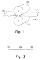
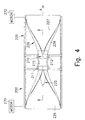
- United States patent US-A-3501818 discloses an extractor arrangement for use with tubular fabric.
- the extractor arrangement includes an inner circular roller 2 and an outer circular roller 3 (see Figures 1, 2) the extraction is accomplished by pressing the tubular knit fabric between this inner circular roller 2 and the outer circular roller 3.
- the present invention takes an entirely different approach by using a cylindrical shaped mandrel as an opener, spreader, of the knit fabric from rope form and as a support.
- the mandrel is positioned inside the sleeve of tubular knit fabric and maintains the tubular shape of the fabric during the extraction and compacting processes.
- Encasing the fabric and the mandrel is a larger diameter tubular ring member which presses the fabric against the mandrel in order to perform the extraction and compaction processes.
- the ring member extends for some distance in the longitudinal direction of travel of the knit fabric and contains a mechanism, such as a detent for retaining the mandrel in place.
- a rope of tubular fabric is conveyed into the mandrel/ring assembly by an endless conveyor or belt made from a flexible material such as rubber.
- a flexible material such as rubber.
- an upper surface of the belt material surrounds the fabric while the lower surface of the belt material comes into contact with the inner surface of the ring member.
- the mandrel, the lower surface of the belt material and inner surface of the ring member are manufactured with smooth surfaces in order to provide frictionless sliding contact therebetween.
- FIG. 3 a perspective view of the compactor/extractor 200 of the present invention.
- the compactor/extractor 200 includes and is supported by frame 205 which is constructed of rails and legs.
- frame 205 is constructed of stainless steel to inhibit rusting of the frame.
- Supported on structure 205 are two pair of rails 207 for mounting the mandrel 220 and ring 210 assembly.
- Ring 210 is mounted to rails 207 via hinged flanges 211 and locking flanges (not shown) on the other side of ring 210.
- ring 210 is constructed from two halves, an upper half and a lower half which are combined into the configuration depicted in Figure 3 only after the mandrel 220 and belt 225 have been inserted thereinto.
- the tubular knit fabric to be finished can be manually threaded onto mandrel 220 and self threaded through the assembled ring 210 by the motion of belt 225.
- the two halves of ring 210 are fastened together, for example, by bolts hinges or other suitable fastening means.
- rollers 230 and 235 Mounted on the ends of frame 205 are drive rollers 230 and 235. These rollers 230 and 235 are rotatably mounted and are driven by an appropriate motor or motors 270, 272 (Fig. 4). As more fully described below, drive rollers 230 and 235 serve to drive the belt 225 which in turn carries the tubular knit fabric into the mandrel 220 and ring 210 assembly. Rollers 230, 235 can be driven synchronously or asynchronously depending on the particular operation being performed.
- a detent 215 is formed in ring 210 in order to retain mandrel 220 in its proper position in ring 210.
- Mandrel 220 has a detent which corresponds to detent 215 in ring 210. Without detent 215, mandrel 210 would be carried along by belt 225 in its direction of travel indicated by arrow A.
- Other mechanisms for retaining mandrel 220 in ring 210 can be used such as having distal end 212 of ring 210 have a smaller diameter than that of proximal end 211.
- mandrel 220 is shaped such that its diameter is less than the diameter of proximal end 212 of ring 210.
- the mandrel 220 and the proximal end 211 of ring 210 are substantially circular in cross section.
- Mandrel 220 and ring 210 are preferably manufactured from stainless steel in order to inhibit rusting.
- belt 225 has two surfaces, an upper surface 227 which comes into contact with the tubular knit fabric as is reaches compactor/extractor, and a lower surface 228 which contacts an inner surface of ring 210 at the point where the tubular knit fabric and belt 225 enter the mandrel 220 and ring 210 assembly.
- the lower surface 228 of belt 225 is in sliding contact with the inner surface of ring 210 and accordingly has a low coefficient of friction.
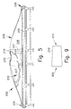
- Figure 5 is side view of the compactor/extractor 200 of the present invention with a portion of belt 225 and ring 210 cut away to reveal mandrel 220 in its operating position. Again, detent 215 in ring 210 is shown, cooperating with a corresponding detent in mandrel 220 in order to maintain mandrel 220 in it proper position.
- frame 205 can be varied, in a preferred embodiment, frame 205 is approximately 7.62 metres (25 feet).
- two mandrel 220 and ring 210 assemblies are mounted to a single frame. The first mandrel 220 ring 210 assembly performing extraction on the tubular knit fabric while the second mandrel 220 ring 210 assembly performs a compaction operation.
- frame 205 is 15.24 m to 30.48 m (fifty to one hundred feet) long.
- This alternative embodiment would also include dryer enclosures for drying the fabric after the extraction process and two different belts 225 of differing hardness for the extraction and compaction processes.
- mandrel 220 is approximately 3.048 m (ten feet) in length with a maximum diameter of 101.6 cm (forty inches).
- Ring 210 is approximately 1.2192 m (four feet) in length with a maximum diameter large enough to accommodate mandrel 200, the thickness of belt 225 and the thickness of tubular knit fabric being processed. This diameter is approximately 1.27 cm to 3.81 cm (one half inch to one and one half inches) greater than the diameter of mandrel 220.
- mandrel 220 and ring 210 are adjusted to accommodate the diameter of the type of tubular knit fabric to be processed. For example, if the diameter of the fabric is 76.2 cm (thirty inches), mandrel 220 should be approximately 76.2 cm (30 inches) in diameter and ring 210 should be only slightly larger.
- adjustable diameter mandrels 220 and rings 210 can be provided or several different size mandrel 220 and rings 210 can be made available for mounting to frame 205.
- different width belts 225 must be provided to accommodate different diameter fabrics.
- frame 205 can have several pairs of rails 207 in order to mount several different diameter mandrel 220 and ring 210 assemblies.
- the ring 210' is formed with a frustoconical shape.
- the front end 300 of ring 210' is large enough to accommodate the incoming belt 225 and tubular knit fabric being processed (see Fig. 3), while the rear end 310 has a diameter such that mandrel 220 (see Fig. 8) will not pulled out of the ring 210' along with the belt 225 and fabric.
- the mandrel 220 does not require any detents as required with the mandrel used in connection with ring 210 depicted in that Figure.
- the diameter of ring 210 at the front end 300 is approximately 1.27 cm to 3.81 cm (one half inch to one and one half inches) greater than the diameter of mandrel 220 and the length is approximately 1.2192 metres (four feet) long.
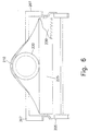
- Figure 6 is a rear view of the compactor/extractor 200 of the present invention. Part of belt 225 has been cut away to reveal roller 230. As shown in this view, distal end of mandrel 220 has a circular cross-section, although this feature is not essential to operation of compactor/extractor 200. the distal end of mandrel 200 which is outside of ring can essentially be of any shape desired. In the preferred embodiment depicted in Figure 6, the shape is circular and is approximately the same diameter as the maximum diameter of mandrel 220. This shape is desired in order to maintain the shape of the tubular knit fabric as it exits ring 210.
- proximal end of mandrel 220 can have a larger diameter cross section in order to transversely stretch a tubular knit fabric after it has been extracted. Furthermore, mandrel 220 can be heated in order to aid in the extraction and drying process.
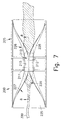
- Figures 7 and 8 depict the compactor/extractor 200 of the present invention when in actual operation.
- Figure 7 is a similar view that of Figure 4, except that a length of tubular knit fabric has been fed on compactor/extractor 200.
- Figure 8 is cross section of Figure 7 taken in the area of mandrel 220 and ring 210.
- tubular knit material 300 is initially fed onto belt 225. If the compactor/extractor 200 is being used for an extraction operation, fabric 300 is most likely in rope form and is saturated with liquid. In the initial setting up of compactor/extractor 200, the fabric is fed onto the distal conical end of mandrel 200 and is carried through ring 210 by the movement of belt 225.
- the compactor/extractor 200 of the present invention when in operation, essentially creates a sandwich configuration consisting of, from top to bottom, ring 210, belt 225, fabric 300, mandrel 220, fabric 300, belt 225 and the bottom half of ring 210.
- belt 225 will move in the direction of arrow A. Due to friction between fabric 300 and belt 225, fabric 300 will be carried along with belt 225 through the mandrel 220 ring 210 assembly.
- the present invention can be used either as a compactor or an extractor.
- the pressure which ring 210 exerts against the belt 225 and fabric 300 will express the liquid out of fabric 300.
- the belt 225 in an extractor 200 is constructed from a relatively hard rubber material with a hardness, for example, of 85 to 90 durometers.
- Mandrel 220 forms the support against which ring 210 exerts this pressure. Since fabric 300 is the element with the greatest degree of compressibility, it will tend to compress and thereby the liquid is squeezed out of the fabric 300.
- the ring 210 and mandrel 220 at point A in Figure 8 essentially form a nip for expressing the water out of fabric 300.
- the amount of compression and therefore the amount of extraction of fabric 300 can be adjusted.
- the sandwich of belt 225 and fabric 300 will not be able to move through the mandrel 220 ring 210 assembly.
- little to no force is exerted on the belt 225 or fabric 300 and therefore no liquid is expressed.
- the forward end of mandrel 220 is lower than the rear end in order to allow the extracted liquid to drain from the machine.
- the present invention can be used either as a compactor or an extractor.
- the function of the mandrel 220 and ring 210 assembly is to longitudinally tighten the stitches in the knit fabric. Compaction is accomplished by the present invention by driving roller 235 at a slightly higher speed than that of roller 230. The difference in speeds will tend to bunch, and therefore feed fabric 300 into the mandrel 220 ring 210 assembly. As the fabric 300 is forced into the gap between the mandrel 220 and the ring 210, the stitches in fabric 300 will be forced together and thereby shrink the length of the fabric 300. The ever closer hatched lines in the fabric 300 depicted in Figure 8 illustrate this compaction of the stitches in fabric 300.
- the belt 225 is preferably made from a material with a greater compressibility than the belt 225 used for the extraction process.
- steam can be applied to tubular knit fabric 300 prior to its entrance to the ring 210 and mandrel 220 assembly.
- the steam provides moisture and heat to the fabric 300 in order to render it more pliable during the compaction process.
- a knife or other cutting device can be placed downstream from the exit end of the ring 210 in order to cut the tubular fabric 300 and deliver it open width to a desired size.
- the cylindrical construction of the apparatus of the present invention allows for finishing of the tubular knit fabric in its tubular form. This solves the greatest single problem with the prior art finishing machines which create creases in the tubular fabric by finishing the fabric in flat form.
- the present invention finishes the tubular fabric without any creases whatsoever. This advantage of the present invention provides a tremendous flexibility for the use of the tubular knit fabric previously unattainable in the prior art.
- the machine is a universal finishing machine and has applicability to all phases of finishing such as bleaching, dying and drying.
- the cylindrical finishing machine of the present invention can be used in a dying process, either submerged in the dye bath itself or through application of the dye while the tubular knit fabric is in its spread state on the mandrel 220. This has clear advantages over the prior art because the edge creases created by the prior art generate inconsistent dying in the crease region.
- the ring 210 and mandrel 220 assembly can be encased in a dryer.
- Belt 225 can also be made of a porous material and a vacuum can be applied to the exterior to aid in the extraction and drying of the fabric.
Landscapes
- Engineering & Computer Science (AREA)
- Textile Engineering (AREA)
- Treatment Of Fiber Materials (AREA)
- Knitting Of Fabric (AREA)
Claims (17)
- Vorrichtung (200) zum Durchführen einer Veredlung einer schlauchförmigen Wirkware (300) ohne Erzeugung von Randfalten in der schlauchförmigen Wirkware (300), wobei die Vorrichtung (200) einen Formkern (220) aufweist, der in einem Ring (210) angeordnet ist, gekennzeichnet durch einen Endlosriemen (225), der an einem Rahmen (205) gehalten wird, der Endlosriemen (225) die schlauchförmige Wirkware (300) befördert, der Ring (210) auch an dem Rahmen (205) gehalten wird, der Ring (210) und der Formkern (220) dafür geeignet sind, den Endlosriemen (225) und die schlauchförmige Wirkware (300) dazwischen aufzunehmen, der Formkern (220) die schlauchförmige Wirkware (300) ausbreitet und die schlauchförmige Wirkware (300) und den Endlosriemen (225) gegen eine innere Oberfläche des Rings (210) presst und dabei die Veredlung durchführt.
- Vorrichtung nach Anspruch 1, ferner dadurch gekennzeichnet, dass die schlauchförmige Wirkware (300) an den Formkern (220) angepasst ist, und wobei der Ring (210) dafür geeignet ist, den Endlosriemen (225) und die schlauchförmige Wirkware (300) aufzunehmen, nachdem die schlauchförmige Wirkware (300) an den Formkern (220) angepasst worden ist.
- Vorrichtung nach Anspruch 2, ferner dadurch gekennzeichnet, dass eine Unterseite (226) des Endlosriemens (225) mit einer Innenseite des Rings in Berührung kommt, und wobei eine Oberseite (227) des Endlosriemens (225) mit einer Außenseite der schlauchförmigen Wirkware (300) in Berührung kommt.
- Vorrichtung nach Anspruch 1, ferner dadurch gekennzeichnet, dass die Vorrichtung ein Absauger bzw. Extraktor ist, und wobei der Formkern (220) und der Ring (210) zusammenwirken, um die schlauchförmige Wirkware (300) zusammenzudrücken und dadurch von dieser eine Flüssigkeit zu extrahieren.
- Vorrichtung nach Anspruch 1, ferner dadurch gekennzeichnet, dass die Vorrichtung ein Verdichter ist, und wobei der Formkern (220) und der Ring (210) zusammenwirken, um eine Längsnaht der schlauchförmigen Wirkware (300) zu verdichten.
- Vorrichtung nach Anspruch 1, ferner dadurch gekennzeichnet, dass der Ring (210) im wesentlichen zylindrisch mit einer ringförmigen Verengung (215) darin ist, und wobei der Formkern (220) eine entsprechende Feststellvorrichtung aufweist, die Feststeilvorrichtungen den Formkern (220) daran hindern, von dem Ring (210) gelöst zu werden.
- Vorrichtung nach Anspruch 1, ferner dadurch gekennzeichnet, dass der Ring (210) eine stumpfkegelige Form aufweist, eine Öffnung in einem Frontende des Rings (210) einen Durchmesser hat, welcher größer als eine Öffnung in einem Hinterende des Rings (210) ist, wodurch der Formkern (220) daran gehindert wird, von dem Ring (210) gelöst zu werden.
- Vorrichtung nach Anspruch 1, ferner dadurch gekennzeichnet, dass der Formkern (220) ein konisch geformtes Frontende zum Aufnehmen der schlauchförmigen Wirkware (300) aufweist und das konische Frontende die schlauchförmige Wirkware (300) von einer Innenseite derselben ausbreitet.
- Vorrichtung nach Anspruch 1, ferner dadurch gekennzeichnet, dass ein Innendurchmesser des Rings (210) größer als eine Kombination aus der Dicke des Endlosriemens (225), der Dicke der schlauchförmigen Wirkware (300) und dem Außendurchmesser des Formkerns (220) ist.
- Vorrichtung nach Anspruch 1, ferner dadurch gekennzeichnet, dass der Endlosriemen (225) aus einem zusammendrückbaren Material hergestellt ist.
- Vorrichtung nach Anspruch 1, ferner gekennzeichnet durch Walzen (230, 235), die an jedes eines Frontendes und eines Hinterendes des Rahmens (205) angebracht sind, der Endlosriemen (225) an die Walzen (230, 235) gekoppelt ist, mindestens ein Antriebsmechanismus (270, 272) an mindestens einer der Walzen (230, 235) angebracht ist, wobei eine Funktion des Antriebsmechanismus (270, 272) mindestens eine Walze (230, 235) dreht und dabei den Endlosriemen (225) bewegt.
- Vorrichtung nach Anspruch 1, ferner dadurch gekennzeichnet, dass der Ring (210) eine erste Hälfte und eine zweite Hälfte hat, die ersten und zweiten Hälften kombiniert sind, sobald der Formkern (220) und der Endlosriemen (225) zwischen die erste Hälfte und die zweite Hälfte eingefügt worden sind.
- Verfahren zum Durchführen einer Veredlung einer schlauchförmigen Wirkware (300) ohne Erzeugung von Randfalten in der schlauchförmigen Wirkware (300), das Verfahren einen Formkern (220) und einen Ring (210) verwendet und gekennzeichnet ist durch ein Befördern der schlauchförmigen Wirkware (300) auf einem Riemen (225), Anbringen der schlauchförmigen Wirkware (300) auf dem Formkern (220), der in dem Ring (210) angeordnet ist, Ausbreiten der schlauchförmigen Wirkware (300) auf seiner röhrenförmigen Form mit dem Formkern (220) und Befördern des Riemens (225) und der schlauchförmigen Wirkware (300) zwischen dem Formkern (220) und dem Ring (210), so dass der Formkern (220) und der Ring (210) einen Druck auf die schlauchförmige Wirkware (300) ausüben und dabei die Veredlung der schlauchförmigen Wirkware (300) durchführen, ohne Randfalten zu erzeugen.
- Verfahren nach Anspruch 13, ferner dadurch gekennzeichnet, dass die schlauchförmige Wirkware (300) zwischen dem Ring (210) und dem Formkern (220) zusammengedrückt wird, um dadurch eine Flüssigkeit aus der schlauchförmigen Wirkware (300) zu extrahieren.
- Verfahren nach Anspruch 13, ferner dadurch gekennzeichnet, dass der Druck durch den Ring (210) und den Formkern (220) eine Längsnaht der schlauchförmigen Wirkware (300) verdichtet.
- Verfahren nach Anspruch 13, ferner dadurch gekennzeichnet, dass der Formkern (220) ein konisches Frontende hat, und wobei der Schritt des Ausbreitens der schlauchförmigen Wirkware (300) durch das konische Frontende des Formkerns (220) erreicht wird.
- Verfahren nach Anspruch 13, bei dem der Rahmen (205) ein Frontende und ein Hinterende hat und Walzen (230, 235) an jedem des Frontendes und des Hinterendes angebracht sind, der Riemen (225) mit den Walzen (230, 235) gekoppelt ist, das Verfahren ferner durch Drehen von mindestens einer Walze (230, 235) gekennzeichnet ist, um dadurch den Riemen (225) zu bewegen.
Applications Claiming Priority (6)
| Application Number | Priority Date | Filing Date | Title |
|---|---|---|---|
| US208661 | 1980-11-20 | ||
| 1997-05-09 | |||
| US7240898P | 1998-01-23 | 1998-01-23 | |
| US72408P | 1998-01-23 | ||
| US09/208,661 US6047452A (en) | 1998-01-23 | 1998-12-10 | Cylindrical belt finishing machine for knit fabric |
| PCT/US1999/000152 WO1999037845A1 (en) | 1998-01-23 | 1999-01-13 | Finishing machine for tubular knit fabric |
Publications (2)
| Publication Number | Publication Date |
|---|---|
| EP1056896A1 EP1056896A1 (de) | 2000-12-06 |
| EP1056896B1 true EP1056896B1 (de) | 2003-03-05 |
Family
ID=22107357
Family Applications (1)
| Application Number | Title | Priority Date | Filing Date |
|---|---|---|---|
| EP99901321A Expired - Lifetime EP1056896B1 (de) | 1998-01-23 | 1999-01-13 | Maschine zur veredlung von schlauchförmiger wirkware |
Country Status (6)
| Country | Link |
|---|---|
| US (1) | US6047452A (de) |
| EP (1) | EP1056896B1 (de) |
| AT (1) | ATE233840T1 (de) |
| AU (1) | AU2104799A (de) |
| DE (1) | DE69905696T2 (de) |
| WO (1) | WO1999037845A1 (de) |
Families Citing this family (4)
| Publication number | Priority date | Publication date | Assignee | Title |
|---|---|---|---|---|
| US6363701B1 (en) * | 1999-12-23 | 2002-04-02 | Jimmy R. Jacumin | Fabric detwister cylinder apparatus |
| EP1460165A1 (de) * | 2003-03-16 | 2004-09-22 | MATEC S.p.A. | Vorrichtung zur Herstellung von Kleidungsstücken ausgehend von schlauchförmigen Gestricken und Herstellungsmethode |
| US8869361B2 (en) * | 2011-12-21 | 2014-10-28 | GKN Aerospace Services Structures, Corp. | Method and apparatus for applying a compaction pressure to a fabric preform during wrapping |
| US9869036B2 (en) | 2015-04-13 | 2018-01-16 | Gkn Aerospace Services Structures Corporation | Apparatus and method for controlling fabric web |
Family Cites Families (22)
| Publication number | Priority date | Publication date | Assignee | Title |
|---|---|---|---|---|
| US779764A (en) * | 1904-07-25 | 1905-01-10 | Charles A Burns | Attachment for sewing-machines for producing drapery-cords. |
| US973530A (en) * | 1909-12-18 | 1910-10-25 | Calvert T Mckane | Folding and guiding attachment for sewing-machines. |
| US1133078A (en) * | 1914-08-15 | 1915-03-23 | Louis N D Williams | Take-up mechanism for knitting-machines. |
| US1259478A (en) * | 1917-01-30 | 1918-03-19 | Arthur Wellington Bechtel | Take-up device for knitting-machines. |
| US1964691A (en) * | 1928-08-01 | 1934-06-26 | Goodyear S India Rubber Glove | Apparatus for treating knit goods |
| US2189166A (en) * | 1937-03-05 | 1940-02-06 | Samcoe Holding Corp | Fabric feeding control system |
| US2294642A (en) * | 1941-05-20 | 1942-09-01 | American Viscose Corp | Apparatus for spreading and stretching fabrics in tubular form |
| US2410146A (en) * | 1944-06-12 | 1946-10-29 | Harold W Birch | Machine for splitting tubular fabric, opening it, and extracting moisture therefrom |
| US3104464A (en) * | 1959-10-05 | 1963-09-24 | Calumet & Hecla | Tubing |
| DE1511070A1 (de) * | 1966-10-19 | 1969-08-07 | Adolf Schmidt | Verfahren und Vorrichtung zum Querrecken oder Querschrumpfen einer Materialbahn |
| US3501818A (en) * | 1968-02-26 | 1970-03-24 | Gmbh Hossmann & Strauss Maschb | Squeezing arrangement for wet tubular webs |
| FR2346134A1 (fr) * | 1976-03-29 | 1977-10-28 | Mercer Ltd F B | Appareil pour l'etirage transversal de matieres tubulaires |
| US4118179A (en) * | 1976-12-08 | 1978-10-03 | Honeywell Inc. | Material processor with relative movement between material and its positioner |
| EP0014787B1 (de) * | 1979-02-20 | 1984-01-25 | Courtaulds Plc | Verfahren und Vorrichtung zum Entfeuchten von luftdurchlässigem schlauchförmigem Material |
| US4266983A (en) * | 1979-03-12 | 1981-05-12 | Courtaulds Limited | Method of, and means for, reducing the liquid content of air-permeable material in tubular form |
| DE2935374C2 (de) * | 1979-09-01 | 1981-01-08 | Lindauer Dornier Gesellschaft Mbh, 8990 Lindau | Von außen gehaltener zylindrischer Breithalter für Schlauchware |
| EP0041787A1 (de) * | 1980-06-05 | 1981-12-16 | Fbc Limited | Herbizide Mischungen |
| EP0250025B1 (de) * | 1986-06-17 | 1988-11-09 | SPEROTTO RIMAR S.p.A. | Vorrichtung zum Kalendern von Schlauchmaschenwaren |
| CA1300864C (en) * | 1987-10-13 | 1992-05-19 | William D. Milligan | Method and apparatus for compressive shrinkage of tubular knitted fabric and the like |
| DE4334897C1 (de) * | 1993-10-13 | 1995-04-20 | Dornier Gmbh Lindauer | Kombinierte Ausbreit- und Quetschvorrichtung, insbesondere für Schlauch-Wirkware |
| US5442842A (en) * | 1993-10-25 | 1995-08-22 | _Guilford Mills, Inc. | Apparatus for guiding longitudinal travel of tubular fabric |
| US5918353A (en) * | 1998-11-25 | 1999-07-06 | Jacumin; Jimmy R. | Continuous fabric detwister |
-
1998
- 1998-12-10 US US09/208,661 patent/US6047452A/en not_active Expired - Lifetime
-
1999
- 1999-01-13 DE DE69905696T patent/DE69905696T2/de not_active Expired - Lifetime
- 1999-01-13 EP EP99901321A patent/EP1056896B1/de not_active Expired - Lifetime
- 1999-01-13 WO PCT/US1999/000152 patent/WO1999037845A1/en not_active Ceased
- 1999-01-13 AU AU21047/99A patent/AU2104799A/en not_active Abandoned
- 1999-01-13 AT AT99901321T patent/ATE233840T1/de not_active IP Right Cessation
Also Published As
| Publication number | Publication date |
|---|---|
| WO1999037845A1 (en) | 1999-07-29 |
| EP1056896A1 (de) | 2000-12-06 |
| AU2104799A (en) | 1999-08-09 |
| US6047452A (en) | 2000-04-11 |
| DE69905696D1 (de) | 2003-04-10 |
| ATE233840T1 (de) | 2003-03-15 |
| DE69905696T2 (de) | 2004-01-15 |
Similar Documents
| Publication | Publication Date | Title |
|---|---|---|
| EP1056896B1 (de) | Maschine zur veredlung von schlauchförmiger wirkware | |
| US3829931A (en) | Machine for recovering meat | |
| FR2414581A1 (fr) | Machine a papier a toile metallique double | |
| DE19744341A1 (de) | Papiermaschine | |
| GB2065487A (en) | Continuous pressing filter | |
| KR860001618B1 (ko) | 긴 닙프 프레스 기구 | |
| Davys et al. | A belt press for separating juices from fibrous pulps | |
| FI56708C (fi) | Foerfarande foer att behandla ett foerut bildat fibertygbana foer att foerbaettra dess kaensel och fall | |
| CS212774B2 (en) | Leather squeezing apparatus | |
| US3654781A (en) | Apparatus for the continuous extraction of water from flat material | |
| CN213538413U (zh) | 一种用于开幅机的脱水机构 | |
| JPS62125074A (ja) | 布防皺処理装置 | |
| AT394665B (de) | Vielzweck-bearbeitungs-vorrichtung | |
| DE19845954A1 (de) | Entwässerungsvorrichtung | |
| US4617809A (en) | Flow press, especially flow sammying machine, for the production and processing of leather | |
| KR890000240B1 (ko) | 직물을 압축수축시키는 방법 및 장치 | |
| KR860001625B1 (ko) | 확장니프 프레스 | |
| DE2757257C3 (de) | Abwelkpresse für Leder, Pelze u.dgl. | |
| GB2141153A (en) | A fabric fulling and washing machine | |
| US5412853A (en) | Apparatus for finishing a fabric web | |
| DE2456921A1 (de) | Einrichtung zum dehnungsfreien, kontinuierlichen pressen und dekatieren von geweben, gewirken und dergleichen | |
| KR860001607B1 (ko) | 프레스 기구 | |
| DE3427002A1 (de) | Abwelkmaschine fuer leder | |
| DE29723115U1 (de) | Papiermaschine | |
| US3704151A (en) | Method for treating tubular fabrics |
Legal Events
| Date | Code | Title | Description |
|---|---|---|---|
| PUAI | Public reference made under article 153(3) epc to a published international application that has entered the european phase |
Free format text: ORIGINAL CODE: 0009012 |
|
| 17P | Request for examination filed |
Effective date: 20000823 |
|
| AK | Designated contracting states |
Kind code of ref document: A1 Designated state(s): AT BE CH CY DE DK ES FI FR GB GR IE IT LI LU MC NL PT SE |
|
| AX | Request for extension of the european patent |
Free format text: AL PAYMENT 20000823;LT PAYMENT 20000823;LV PAYMENT 20000823;MK PAYMENT 20000823;RO PAYMENT 20000823;SI PAYMENT 20000823 |
|
| GRAG | Despatch of communication of intention to grant |
Free format text: ORIGINAL CODE: EPIDOS AGRA |
|
| 17Q | First examination report despatched |
Effective date: 20010719 |
|
| RAP3 | Party data changed (applicant data changed or rights of an application transferred) |
Owner name: CARUSO, FRANK |
|
| RIN1 | Information on inventor provided before grant (corrected) |
Inventor name: CARUSO, FRANK |
|
| GRAG | Despatch of communication of intention to grant |
Free format text: ORIGINAL CODE: EPIDOS AGRA |
|
| GRAG | Despatch of communication of intention to grant |
Free format text: ORIGINAL CODE: EPIDOS AGRA |
|
| GRAH | Despatch of communication of intention to grant a patent |
Free format text: ORIGINAL CODE: EPIDOS IGRA |
|
| GRAH | Despatch of communication of intention to grant a patent |
Free format text: ORIGINAL CODE: EPIDOS IGRA |
|
| GRAA | (expected) grant |
Free format text: ORIGINAL CODE: 0009210 |
|
| AK | Designated contracting states |
Designated state(s): AT BE CH CY DE DK ES FI FR GB GR IE IT LI LU MC NL PT SE |
|
| AX | Request for extension of the european patent |
Extension state: AL LT LV MK RO SI |
|
| PG25 | Lapsed in a contracting state [announced via postgrant information from national office to epo] |
Ref country code: NL Free format text: LAPSE BECAUSE OF FAILURE TO SUBMIT A TRANSLATION OF THE DESCRIPTION OR TO PAY THE FEE WITHIN THE PRESCRIBED TIME-LIMIT Effective date: 20030305 Ref country code: GR Free format text: LAPSE BECAUSE OF FAILURE TO SUBMIT A TRANSLATION OF THE DESCRIPTION OR TO PAY THE FEE WITHIN THE PRESCRIBED TIME-LIMIT Effective date: 20030305 Ref country code: FI Free format text: LAPSE BECAUSE OF FAILURE TO SUBMIT A TRANSLATION OF THE DESCRIPTION OR TO PAY THE FEE WITHIN THE PRESCRIBED TIME-LIMIT Effective date: 20030305 Ref country code: CY Free format text: LAPSE BECAUSE OF FAILURE TO SUBMIT A TRANSLATION OF THE DESCRIPTION OR TO PAY THE FEE WITHIN THE PRESCRIBED TIME-LIMIT Effective date: 20030305 Ref country code: BE Free format text: LAPSE BECAUSE OF FAILURE TO SUBMIT A TRANSLATION OF THE DESCRIPTION OR TO PAY THE FEE WITHIN THE PRESCRIBED TIME-LIMIT Effective date: 20030305 Ref country code: AT Free format text: LAPSE BECAUSE OF FAILURE TO SUBMIT A TRANSLATION OF THE DESCRIPTION OR TO PAY THE FEE WITHIN THE PRESCRIBED TIME-LIMIT Effective date: 20030305 |
|
| REG | Reference to a national code |
Ref country code: GB Ref legal event code: FG4D |
|
| REG | Reference to a national code |
Ref country code: CH Ref legal event code: NV Representative=s name: TROESCH SCHEIDEGGER WERNER AG Ref country code: CH Ref legal event code: EP |
|
| REG | Reference to a national code |
Ref country code: IE Ref legal event code: FG4D |
|
| REF | Corresponds to: |
Ref document number: 69905696 Country of ref document: DE Date of ref document: 20030410 Kind code of ref document: P |
|
| PG25 | Lapsed in a contracting state [announced via postgrant information from national office to epo] |
Ref country code: SE Free format text: LAPSE BECAUSE OF FAILURE TO SUBMIT A TRANSLATION OF THE DESCRIPTION OR TO PAY THE FEE WITHIN THE PRESCRIBED TIME-LIMIT Effective date: 20030605 Ref country code: PT Free format text: LAPSE BECAUSE OF FAILURE TO SUBMIT A TRANSLATION OF THE DESCRIPTION OR TO PAY THE FEE WITHIN THE PRESCRIBED TIME-LIMIT Effective date: 20030605 Ref country code: DK Free format text: LAPSE BECAUSE OF FAILURE TO SUBMIT A TRANSLATION OF THE DESCRIPTION OR TO PAY THE FEE WITHIN THE PRESCRIBED TIME-LIMIT Effective date: 20030605 |
|
| NLV1 | Nl: lapsed or annulled due to failure to fulfill the requirements of art. 29p and 29m of the patents act | ||
| LTIE | Lt: invalidation of european patent or patent extension |
Effective date: 20030305 |
|
| PG25 | Lapsed in a contracting state [announced via postgrant information from national office to epo] |
Ref country code: ES Free format text: LAPSE BECAUSE OF FAILURE TO SUBMIT A TRANSLATION OF THE DESCRIPTION OR TO PAY THE FEE WITHIN THE PRESCRIBED TIME-LIMIT Effective date: 20030930 |
|
| ET | Fr: translation filed | ||
| PLBE | No opposition filed within time limit |
Free format text: ORIGINAL CODE: 0009261 |
|
| STAA | Information on the status of an ep patent application or granted ep patent |
Free format text: STATUS: NO OPPOSITION FILED WITHIN TIME LIMIT |
|
| PG25 | Lapsed in a contracting state [announced via postgrant information from national office to epo] |
Ref country code: LU Free format text: LAPSE BECAUSE OF NON-PAYMENT OF DUE FEES Effective date: 20040113 Ref country code: IE Free format text: LAPSE BECAUSE OF NON-PAYMENT OF DUE FEES Effective date: 20040113 Ref country code: GB Free format text: LAPSE BECAUSE OF NON-PAYMENT OF DUE FEES Effective date: 20040113 |
|
| PG25 | Lapsed in a contracting state [announced via postgrant information from national office to epo] |
Ref country code: MC Free format text: LAPSE BECAUSE OF NON-PAYMENT OF DUE FEES Effective date: 20040131 |
|
| 26N | No opposition filed |
Effective date: 20031208 |
|
| GBPC | Gb: european patent ceased through non-payment of renewal fee |
Effective date: 20040113 |
|
| REG | Reference to a national code |
Ref country code: IE Ref legal event code: MM4A |
|
| PGFP | Annual fee paid to national office [announced via postgrant information from national office to epo] |
Ref country code: FR Payment date: 20090119 Year of fee payment: 11 |
|
| REG | Reference to a national code |
Ref country code: FR Ref legal event code: ST Effective date: 20100930 |
|
| PG25 | Lapsed in a contracting state [announced via postgrant information from national office to epo] |
Ref country code: FR Free format text: LAPSE BECAUSE OF NON-PAYMENT OF DUE FEES Effective date: 20100201 |
|
| PGFP | Annual fee paid to national office [announced via postgrant information from national office to epo] |
Ref country code: CH Payment date: 20120125 Year of fee payment: 14 |
|
| REG | Reference to a national code |
Ref country code: CH Ref legal event code: PL |
|
| PG25 | Lapsed in a contracting state [announced via postgrant information from national office to epo] |
Ref country code: CH Free format text: LAPSE BECAUSE OF NON-PAYMENT OF DUE FEES Effective date: 20130131 Ref country code: LI Free format text: LAPSE BECAUSE OF NON-PAYMENT OF DUE FEES Effective date: 20130131 |
|
| PGFP | Annual fee paid to national office [announced via postgrant information from national office to epo] |
Ref country code: DE Payment date: 20170125 Year of fee payment: 19 |
|
| PGFP | Annual fee paid to national office [announced via postgrant information from national office to epo] |
Ref country code: IT Payment date: 20170124 Year of fee payment: 19 |
|
| REG | Reference to a national code |
Ref country code: DE Ref legal event code: R119 Ref document number: 69905696 Country of ref document: DE |
|
| PG25 | Lapsed in a contracting state [announced via postgrant information from national office to epo] |
Ref country code: DE Free format text: LAPSE BECAUSE OF NON-PAYMENT OF DUE FEES Effective date: 20180801 |
|
| PG25 | Lapsed in a contracting state [announced via postgrant information from national office to epo] |
Ref country code: IT Free format text: LAPSE BECAUSE OF NON-PAYMENT OF DUE FEES Effective date: 20180113 |