US5918353A - Continuous fabric detwister - Google Patents
Continuous fabric detwister Download PDFInfo
- Publication number
- US5918353A US5918353A US09/199,738 US19973898A US5918353A US 5918353 A US5918353 A US 5918353A US 19973898 A US19973898 A US 19973898A US 5918353 A US5918353 A US 5918353A
- Authority
- US
- United States
- Prior art keywords
- cylinder
- fabric
- rollers
- detwisting
- chain
- Prior art date
- Legal status (The legal status is an assumption and is not a legal conclusion. Google has not performed a legal analysis and makes no representation as to the accuracy of the status listed.)
- Expired - Fee Related
Links
- 239000004744 fabric Substances 0.000 title abstract description 29
- 239000012530 fluid Substances 0.000 claims abstract description 5
- 239000000463 material Substances 0.000 claims description 16
- 238000011144 upstream manufacturing Methods 0.000 claims description 4
- 230000007246 mechanism Effects 0.000 abstract description 7
- 238000004061 bleaching Methods 0.000 description 6
- 238000000034 method Methods 0.000 description 3
- 238000010276 construction Methods 0.000 description 2
- 238000005260 corrosion Methods 0.000 description 1
- 230000007797 corrosion Effects 0.000 description 1
- 230000001419 dependent effect Effects 0.000 description 1
- 238000004043 dyeing Methods 0.000 description 1
- 230000000694 effects Effects 0.000 description 1
- 230000002452 interceptive effect Effects 0.000 description 1
- 238000012423 maintenance Methods 0.000 description 1
- 238000009877 rendering Methods 0.000 description 1
- 230000002441 reversible effect Effects 0.000 description 1
- 230000000007 visual effect Effects 0.000 description 1
- XLYOFNOQVPJJNP-UHFFFAOYSA-N water Substances O XLYOFNOQVPJJNP-UHFFFAOYSA-N 0.000 description 1
Images


Classifications
-
- D—TEXTILES; PAPER
- D06—TREATMENT OF TEXTILES OR THE LIKE; LAUNDERING; FLEXIBLE MATERIALS NOT OTHERWISE PROVIDED FOR
- D06B—TREATING TEXTILE MATERIALS USING LIQUIDS, GASES OR VAPOURS
- D06B23/00—Component parts, details, or accessories of apparatus or machines, specially adapted for the treating of textile materials, not restricted to a particular kind of apparatus, provided for in groups D06B1/00 - D06B21/00
- D06B23/08—Untwisting devices
Definitions
- This invention pertains to a device which detwists continuous tubular knit fabric such as when it leaves a bleaching kier or washer.
- a fabric detwisting apparatus having its primary function in the continuous in-line treatment of an elongated mass of flaccid material, especially tubular shaped knitted fabrics undergoing bleaching, dyeing and finishing operations.
- the detwister itself may be used, but is not so limited, between a bleaching kier and a washer and is usually employed in conjunction with some type of conveyor of elongated tubular flaccid material.
- the detwister comprises a cylinder which is adapted to rotate in either direction dependent upon the direction of twist previously imparted to the material, in combination with a source of compressed gas, such as air, which is directed to the interior of the tubular flaccid material while such material is present within the rotating cylinder.
- the gas causes the material to expand so as to impinge against the interior wall of the bi-directional rotating cylinder, thereby continuously imparting a twist to the flaccid mass which is opposite to that which previously had been imparted to the material in its construction or by prior handling in the kier or the like.
- a detwisting effect is thereby achieved on a continuous processing basis sufficient in extent to keep the elongated, flaccid mass from knotting or kinking up during processing, thus rendering the process sought to be carried out more effective than it otherwise would have been.
- FIG. 1 shows a perspective view taken from beneath a preferred embodiment of the invention which is cut away to reveal drive means for rotation of the cylinder;
- FIG. 2 illustrates a perspective view taken from above the apparatus of FIG. 1, disclosing gutters to route excess fluid away from the drive mechanism;
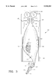
- FIG. 3 demonstrates a schematic cross-section of the preferred embodiment of the invention showing the shape taken by the tubular flaccid material during detwisting.
- FIG. 1 shows preferred fabric detwisting apparatus or device 10, which comprises rectangular housing or frame 11 attached to funnel 18, partially broken for illustration purposes.
- Continuous fabric 12 enters circular guide 13 and passes through non-powered rollers 14 and 15 in a sinuous fashion.
- Guide 13 and non-powered rollers 14 and 15 are adjustably mounted by pins 55 (only one shown) on frame 16 which includes hinge 17 formed by conventional elongate members and pins.
- Frame 16 is rigidly affixed to cylinder 20 positioned within housing 11.
- Gutters 21 and 22 are positioned on opposing side walls 23 and 24 respectively.
- Tracks 25 and 26 circumscribe cylinder 20 proximate opposing ends 27 and 28 respectively.
- Rollers 29 and 30 are positioned on track 25 while rollers 31 and 32 are positioned on track 26.
- rollers 29 and 31 While two rollers are shown for every rod, it is possible to use only the lower rollers 29 and 31. Additionally, as shown, it appears that cylinder 20 is supported on only a pair of rollers, but in actuality, rollers are positioned at every corner of frame 11 to provide proper support.
- Chain 33 is proximate track 25 and is driven by sprocket 34.
- Sprocket 34, rollers 29 and 31 are controlled and driven by rod 35 while rollers 30 and 32 serve as supporting idlers and are connected by rod 36.
- Other drive mechanisms do exist, such as a rack and pinion drive, a belt drive, a worm gear, a friction drive or other equivalent driving mechanisms.
- a sensor similar to the twist sensor disclosed in the '131 patent or visual observation detects twists in continuous tubular fabric 12 and sends a signal to a motor (also not shown) which reversibly drives sprocket 34 in a direction opposite that of the detected twist.
- a motor also not shown
- the twist sensor detects a clockwise twist or the operator visually detects a twist
- the sensor or operator instructs cylinder 20 to rotate counter-clockwise to detwist fabric 12.
- the twist sensor detects a counter-clockwise twist the sensor or operator instructs cylinder 20 to rotate clockwise to detwist fabric 12.
- a reversible motor is preferred, it is possible to include two uni-directional motors which are separately activated as needed to drive sprocket 34, which turns chain 33 and rotates cylinder 20.
- Gutters 21 and 22 are better seen in FIG. 2 which illustrates gutter openings 38 and 39 for gutters 21 and 22 respectively. Fabric 12 and additional parts discussed below have been removed for clarity in this figure. Gutters 21 and 22 allow water or fluid squeezed from fabric 12 by rollers 40-45 (FIG. 3) to drain downwardly past cylinder 20 and back into the bleaching kier (not shown) or other processing vat without interfering with the drive mechanism associated with cylinder 20. This prevents corrosion and the like and is thus desirable from a preventative maintenance standpoint.
- Shaft 35 is attached perpendicularly by a universal joint to shaft 37 which allows rotation of cylinder 20 by an operator if such is desired. Shaft 37 is then attached to the motor to drive cylinder 20 as above described. Alternative conventional joints may be used in place of the universal joint.
- FIG. 3 the method of operation of detwisting apparatus 10 is seen in operation. Specifically continuous tubular fabric 12 passes through adjustable guide 13 and adjustable rollers 14 and 15 prior to entering cylinder 20. Air is forced into continuous fabric 12 by conventional air jets 47 and 48, thus inflating fabric 12 into balloon 49 which presses against inner surface 50 of cylinder 20. As cylinder 20 rotates, balloon 49 presses against inner surface 50, which also rotates allowing fabric 12 to be detwisted. Rollers 40-43 are non-powered rollers which limit the size of balloon 49 on downstream end 51 and help to inject air as well as reducing the possibility of edge distortion.
- non-powered rollers 14 and 15 also limit the size of balloon 49, but from upstream end 52, providing continuous trapping of the air between rollers 14-15 and 44-45. Rollers 14-15 further prevent air from going back through fabric 12 into the bleaching kier which would hamper the continuous movement of fabric 12. In the event air is passing through rollers 14-15 and entering the bleaching kier, rollers 14-15 and guide 13 may be repositioned on pins 55 to effectively cut off air passing therethrough.
- Powered rollers 44 and 45 provide the motive force to pull fabric 12 through detwisting apparatus 10 and further squeeze fluid from fabric 12 for disposal through gutters 21 and 22.
Landscapes
- Engineering & Computer Science (AREA)
- Textile Engineering (AREA)
- Treatment Of Fiber Materials (AREA)
Abstract
Description
Claims (6)
Priority Applications (1)
| Application Number | Priority Date | Filing Date | Title |
|---|---|---|---|
| US09/199,738 US5918353A (en) | 1998-11-25 | 1998-11-25 | Continuous fabric detwister |
Applications Claiming Priority (1)
| Application Number | Priority Date | Filing Date | Title |
|---|---|---|---|
| US09/199,738 US5918353A (en) | 1998-11-25 | 1998-11-25 | Continuous fabric detwister |
Publications (1)
| Publication Number | Publication Date |
|---|---|
| US5918353A true US5918353A (en) | 1999-07-06 |
Family
ID=22738807
Family Applications (1)
| Application Number | Title | Priority Date | Filing Date |
|---|---|---|---|
| US09/199,738 Expired - Fee Related US5918353A (en) | 1998-11-25 | 1998-11-25 | Continuous fabric detwister |
Country Status (1)
| Country | Link |
|---|---|
| US (1) | US5918353A (en) |
Cited By (5)
| Publication number | Priority date | Publication date | Assignee | Title |
|---|---|---|---|---|
| US6047452A (en) * | 1998-01-23 | 2000-04-11 | Caruso; Frank | Cylindrical belt finishing machine for knit fabric |
| US6363701B1 (en) | 1999-12-23 | 2002-04-02 | Jimmy R. Jacumin | Fabric detwister cylinder apparatus |
| EP1433731A1 (en) * | 2002-12-23 | 2004-06-30 | The Procter & Gamble Company | Web twister removal apparatus |
| CN104611824A (en) * | 2013-11-04 | 2015-05-13 | 上海联净电子科技有限公司 | Lifting type heating device and circular knitting machine with lifting type heating device |
| US10947078B2 (en) * | 2018-01-24 | 2021-03-16 | Milliken & Company | Winding system for elongated elements |
Citations (20)
| Publication number | Priority date | Publication date | Assignee | Title |
|---|---|---|---|---|
| US140320A (en) * | 1873-06-24 | Improvement in machines for napping, brushing | ||
| GB340123A (en) * | 1929-12-14 | 1930-12-24 | Frederik Adriaan Witlich Meyne | Improvements in apparatus for untwisting and teasing twisted skeins of fibre or other material |
| US2117603A (en) * | 1936-07-24 | 1938-05-17 | Dungler Julien | Opening of textile fabrics from rope form |
| US2248962A (en) * | 1940-05-09 | 1941-07-15 | Cook Percy | Web manipulating apparatus |
| US2350071A (en) * | 1942-03-11 | 1944-05-30 | Wendell H Shields | Cloth spreading device |
| GB677647A (en) * | 1949-07-27 | 1952-08-20 | Bradford Dyers Ass Ltd | Apparatus for untwisting material in twisted rope form |
| US2836012A (en) * | 1956-06-18 | 1958-05-27 | Bradford Dyers Ass Ltd | Apparatus for untwisting material in twisted rope form |
| US3501818A (en) * | 1968-02-26 | 1970-03-24 | Gmbh Hossmann & Strauss Maschb | Squeezing arrangement for wet tubular webs |
| US3693336A (en) * | 1971-04-19 | 1972-09-26 | Mount Hope Machinery Ltd | Cloth detwister apparatus |
| US3813862A (en) * | 1972-03-31 | 1974-06-04 | I Tsuchida | Apparatus for detecting and correcting torsion of travelling fabric |
| US4241570A (en) * | 1978-07-31 | 1980-12-30 | Siemens Aktiengesellschaft | Method and apparatus for separating twisted wires |
| US4266983A (en) * | 1979-03-12 | 1981-05-12 | Courtaulds Limited | Method of, and means for, reducing the liquid content of air-permeable material in tubular form |
| US4286428A (en) * | 1979-05-04 | 1981-09-01 | Mariano Bassani | Apparatus for detwisting textile fabrics in rope form |
| US4843669A (en) * | 1986-10-16 | 1989-07-04 | Bruckner Apparatebau Gmbh | Method for wet processing of tubular textile material |
| US5119646A (en) * | 1991-03-04 | 1992-06-09 | Jacumin Jimmy R | Bleaching kier for continuous bleaching of elongated cloth |
| US5271131A (en) * | 1992-05-29 | 1993-12-21 | Jacumin Jimmy R | Continuous fabric detwister |
| US5442842A (en) * | 1993-10-25 | 1995-08-22 | _Guilford Mills, Inc. | Apparatus for guiding longitudinal travel of tubular fabric |
| US5551133A (en) * | 1994-05-09 | 1996-09-03 | Albrecht Equipamentos Industrials Ltda., | Device to correct the longitudinal torsion in a tubular fabric |
| US5666704A (en) * | 1995-10-12 | 1997-09-16 | Tubular Textile Llc | Detwisting mechanism for fabric processing line |
| US5718107A (en) * | 1996-12-30 | 1998-02-17 | Catallo; Frank | Fabric detwister |
-
1998
- 1998-11-25 US US09/199,738 patent/US5918353A/en not_active Expired - Fee Related
Patent Citations (20)
| Publication number | Priority date | Publication date | Assignee | Title |
|---|---|---|---|---|
| US140320A (en) * | 1873-06-24 | Improvement in machines for napping, brushing | ||
| GB340123A (en) * | 1929-12-14 | 1930-12-24 | Frederik Adriaan Witlich Meyne | Improvements in apparatus for untwisting and teasing twisted skeins of fibre or other material |
| US2117603A (en) * | 1936-07-24 | 1938-05-17 | Dungler Julien | Opening of textile fabrics from rope form |
| US2248962A (en) * | 1940-05-09 | 1941-07-15 | Cook Percy | Web manipulating apparatus |
| US2350071A (en) * | 1942-03-11 | 1944-05-30 | Wendell H Shields | Cloth spreading device |
| GB677647A (en) * | 1949-07-27 | 1952-08-20 | Bradford Dyers Ass Ltd | Apparatus for untwisting material in twisted rope form |
| US2836012A (en) * | 1956-06-18 | 1958-05-27 | Bradford Dyers Ass Ltd | Apparatus for untwisting material in twisted rope form |
| US3501818A (en) * | 1968-02-26 | 1970-03-24 | Gmbh Hossmann & Strauss Maschb | Squeezing arrangement for wet tubular webs |
| US3693336A (en) * | 1971-04-19 | 1972-09-26 | Mount Hope Machinery Ltd | Cloth detwister apparatus |
| US3813862A (en) * | 1972-03-31 | 1974-06-04 | I Tsuchida | Apparatus for detecting and correcting torsion of travelling fabric |
| US4241570A (en) * | 1978-07-31 | 1980-12-30 | Siemens Aktiengesellschaft | Method and apparatus for separating twisted wires |
| US4266983A (en) * | 1979-03-12 | 1981-05-12 | Courtaulds Limited | Method of, and means for, reducing the liquid content of air-permeable material in tubular form |
| US4286428A (en) * | 1979-05-04 | 1981-09-01 | Mariano Bassani | Apparatus for detwisting textile fabrics in rope form |
| US4843669A (en) * | 1986-10-16 | 1989-07-04 | Bruckner Apparatebau Gmbh | Method for wet processing of tubular textile material |
| US5119646A (en) * | 1991-03-04 | 1992-06-09 | Jacumin Jimmy R | Bleaching kier for continuous bleaching of elongated cloth |
| US5271131A (en) * | 1992-05-29 | 1993-12-21 | Jacumin Jimmy R | Continuous fabric detwister |
| US5442842A (en) * | 1993-10-25 | 1995-08-22 | _Guilford Mills, Inc. | Apparatus for guiding longitudinal travel of tubular fabric |
| US5551133A (en) * | 1994-05-09 | 1996-09-03 | Albrecht Equipamentos Industrials Ltda., | Device to correct the longitudinal torsion in a tubular fabric |
| US5666704A (en) * | 1995-10-12 | 1997-09-16 | Tubular Textile Llc | Detwisting mechanism for fabric processing line |
| US5718107A (en) * | 1996-12-30 | 1998-02-17 | Catallo; Frank | Fabric detwister |
Cited By (9)
| Publication number | Priority date | Publication date | Assignee | Title |
|---|---|---|---|---|
| US6047452A (en) * | 1998-01-23 | 2000-04-11 | Caruso; Frank | Cylindrical belt finishing machine for knit fabric |
| US6363701B1 (en) | 1999-12-23 | 2002-04-02 | Jimmy R. Jacumin | Fabric detwister cylinder apparatus |
| EP1433731A1 (en) * | 2002-12-23 | 2004-06-30 | The Procter & Gamble Company | Web twister removal apparatus |
| US20040129752A1 (en) * | 2002-12-23 | 2004-07-08 | The Procter & Gamble Company | Web twister removal process |
| WO2004058615A1 (en) * | 2002-12-23 | 2004-07-15 | The Procter & Gamble Company | Web twister removal apparatus |
| US7065948B2 (en) * | 2002-12-23 | 2006-06-27 | The Procter & Gamble Company | Web twister removal process |
| CN104611824A (en) * | 2013-11-04 | 2015-05-13 | 上海联净电子科技有限公司 | Lifting type heating device and circular knitting machine with lifting type heating device |
| CN104611824B (en) * | 2013-11-04 | 2016-10-05 | 上海联净电子科技有限公司 | Lift heater and there is the circular knitting machine of this lift heater |
| US10947078B2 (en) * | 2018-01-24 | 2021-03-16 | Milliken & Company | Winding system for elongated elements |
Similar Documents
| Publication | Publication Date | Title |
|---|---|---|
| US4525955A (en) | Abrasive belt cleaning system | |
| US3965523A (en) | Bearing washer | |
| US5918353A (en) | Continuous fabric detwister | |
| EP0197502B1 (en) | High pressure fluid processing device | |
| EP0942090A4 (en) | Band-like cloth processing apparatus | |
| US5271131A (en) | Continuous fabric detwister | |
| WO1999054538A3 (en) | Machine for treating the surface of at least one textile web of endless fabric, especially for napping and/or emerizing or the like | |
| KR100348186B1 (en) | Select apparatus and separate of a garlic | |
| US4059926A (en) | Chain finishing system | |
| KR20010073876A (en) | A screening equipment for the globe-shaped farm products with a dry cleaner | |
| US2798340A (en) | Apparatus for grinding internal surfaces | |
| US2684500A (en) | Apparatus for deveining shrimp | |
| JPH07216721A (en) | Method for treating fiber web and its apparatus | |
| US5566433A (en) | Method and apparatus for treatment of pile fabric | |
| GB2389170A (en) | A conveyer type drying apparatus | |
| CA1321319C (en) | Sausage twisting apparatus and method | |
| US3759434A (en) | Threading mechanism | |
| KR940005762Y1 (en) | Spreading device for textile fabrics | |
| US5749155A (en) | Device for removing liquid on a gauze conveyor and hollow roll comprising a tube for use in such a device | |
| JP2009084730A (en) | Unit for relaxing fabric tension and apparatus for relaxing fabric tension | |
| ATE4176T1 (en) | STRAIGHTENING MACHINE FOR THIN-WALLED PIPES. | |
| JPS62107973A (en) | Polishing device for belt sander | |
| US4189872A (en) | Abrading apparatus and method having induced air | |
| KR200273137Y1 (en) | A device for removing water adhered to edge of strip | |
| US3916492A (en) | Apparatus for spreading tubular fabric |
Legal Events
| Date | Code | Title | Description |
|---|---|---|---|
| AS | Assignment |
Owner name: FLEET CAPITAL CORPORATION, AS AGENT, WISCONSIN Free format text: SECURITY INTEREST;ASSIGNOR:ASHBY INDUSTRIES, INC.;REEL/FRAME:010648/0763 Effective date: 20000211 |
|
| AS | Assignment |
Owner name: ASHBY INDUSTRIES, INC., VIRGINIA Free format text: ASSIGNMENT OF ASSIGNORS INTEREST;ASSIGNOR:JACUMIN, JIMMY R.;REEL/FRAME:010572/0500 Effective date: 20000211 |
|
| AS | Assignment |
Owner name: CHURCHILL CAPITAL PARTNERS III, L.P., MINNESOTA Free format text: SECURITY INTEREST;ASSIGNOR:ASHBY INDUSTRIES, INC.;REEL/FRAME:010685/0520 Effective date: 20000217 |
|
| AS | Assignment |
Owner name: TT MACHINERY HOLDINGS, INC., A CORP. OF DELAWARE, Free format text: ASSIGNMENT OF MORTGAGE;ASSIGNOR:FLEET CAPITAL CORPORATION, A CORP. OF RHODE ISLAND;REEL/FRAME:013599/0353 Effective date: 20020828 |
|
| AS | Assignment |
Owner name: FB COMMERCIAL FINANCE, INC., MISSOURI Free format text: SECURITY INTEREST;ASSIGNOR:ASHBY INDUSTRIES, INC.;REEL/FRAME:013653/0311 Effective date: 20021226 |
|
| REMI | Maintenance fee reminder mailed | ||
| LAPS | Lapse for failure to pay maintenance fees | ||
| STCH | Information on status: patent discontinuation |
Free format text: PATENT EXPIRED DUE TO NONPAYMENT OF MAINTENANCE FEES UNDER 37 CFR 1.362 |
|
| FP | Lapsed due to failure to pay maintenance fee |
Effective date: 20030706 |
|
| AS | Assignment |
Owner name: TUBULAR TEXTILE LLC, NORTH CAROLINA Free format text: RELEASE OF SECURITY AGREEMENT;ASSIGNOR:CHURCHILL CAPITAL PARTNERS III, L.P.;REEL/FRAME:014692/0810 Effective date: 20040528 Owner name: TUBULAR TEXTILE LLC, NORTH CAROLINA Free format text: RELEASE OF SECURITY AGREEMENT;ASSIGNOR:FB COMMERCIAL FINANCE, INC.;REEL/FRAME:014692/0830 Effective date: 20040528 |