EP1056481B1 - Verfahren und anordnung zur sterilisation von hohlkörpern - Google Patents
Verfahren und anordnung zur sterilisation von hohlkörpern Download PDFInfo
- Publication number
- EP1056481B1 EP1056481B1 EP99903726A EP99903726A EP1056481B1 EP 1056481 B1 EP1056481 B1 EP 1056481B1 EP 99903726 A EP99903726 A EP 99903726A EP 99903726 A EP99903726 A EP 99903726A EP 1056481 B1 EP1056481 B1 EP 1056481B1
- Authority
- EP
- European Patent Office
- Prior art keywords
- hollow body
- agent
- opening
- suction
- tube
- Prior art date
- Legal status (The legal status is an assumption and is not a legal conclusion. Google has not performed a legal analysis and makes no representation as to the accuracy of the status listed.)
- Expired - Lifetime
Links
Images

Classifications
-
- A—HUMAN NECESSITIES
- A61—MEDICAL OR VETERINARY SCIENCE; HYGIENE
- A61L—METHODS OR APPARATUS FOR STERILISING MATERIALS OR OBJECTS IN GENERAL; DISINFECTION, STERILISATION OR DEODORISATION OF AIR; CHEMICAL ASPECTS OF BANDAGES, DRESSINGS, ABSORBENT PADS OR SURGICAL ARTICLES; MATERIALS FOR BANDAGES, DRESSINGS, ABSORBENT PADS OR SURGICAL ARTICLES
- A61L2/00—Methods or apparatus for disinfecting or sterilising materials or objects other than foodstuffs or contact lenses; Accessories therefor
- A61L2/16—Methods or apparatus for disinfecting or sterilising materials or objects other than foodstuffs or contact lenses; Accessories therefor using chemical substances
- A61L2/20—Gaseous substances, e.g. vapours
- A61L2/208—Hydrogen peroxide
-
- B—PERFORMING OPERATIONS; TRANSPORTING
- B29—WORKING OF PLASTICS; WORKING OF SUBSTANCES IN A PLASTIC STATE IN GENERAL
- B29C—SHAPING OR JOINING OF PLASTICS; SHAPING OF MATERIAL IN A PLASTIC STATE, NOT OTHERWISE PROVIDED FOR; AFTER-TREATMENT OF THE SHAPED PRODUCTS, e.g. REPAIRING
- B29C49/00—Blow-moulding, i.e. blowing a preform or parison to a desired shape within a mould; Apparatus therefor
- B29C49/42—Component parts, details or accessories; Auxiliary operations
-
- A—HUMAN NECESSITIES
- A61—MEDICAL OR VETERINARY SCIENCE; HYGIENE
- A61L—METHODS OR APPARATUS FOR STERILISING MATERIALS OR OBJECTS IN GENERAL; DISINFECTION, STERILISATION OR DEODORISATION OF AIR; CHEMICAL ASPECTS OF BANDAGES, DRESSINGS, ABSORBENT PADS OR SURGICAL ARTICLES; MATERIALS FOR BANDAGES, DRESSINGS, ABSORBENT PADS OR SURGICAL ARTICLES
- A61L2202/00—Aspects relating to methods or apparatus for disinfecting or sterilising materials or objects
- A61L2202/20—Targets to be treated
- A61L2202/23—Containers, e.g. vials, bottles, syringes, mail
-
- B—PERFORMING OPERATIONS; TRANSPORTING
- B29—WORKING OF PLASTICS; WORKING OF SUBSTANCES IN A PLASTIC STATE IN GENERAL
- B29C—SHAPING OR JOINING OF PLASTICS; SHAPING OF MATERIAL IN A PLASTIC STATE, NOT OTHERWISE PROVIDED FOR; AFTER-TREATMENT OF THE SHAPED PRODUCTS, e.g. REPAIRING
- B29C2949/00—Indexing scheme relating to blow-moulding
- B29C2949/07—Preforms or parisons characterised by their configuration
- B29C2949/0715—Preforms or parisons characterised by their configuration the preform having one end closed
-
- B—PERFORMING OPERATIONS; TRANSPORTING
- B29—WORKING OF PLASTICS; WORKING OF SUBSTANCES IN A PLASTIC STATE IN GENERAL
- B29C—SHAPING OR JOINING OF PLASTICS; SHAPING OF MATERIAL IN A PLASTIC STATE, NOT OTHERWISE PROVIDED FOR; AFTER-TREATMENT OF THE SHAPED PRODUCTS, e.g. REPAIRING
- B29C49/00—Blow-moulding, i.e. blowing a preform or parison to a desired shape within a mould; Apparatus therefor
- B29C49/02—Combined blow-moulding and manufacture of the preform or the parison
- B29C49/06—Injection blow-moulding
-
- B—PERFORMING OPERATIONS; TRANSPORTING
- B29—WORKING OF PLASTICS; WORKING OF SUBSTANCES IN A PLASTIC STATE IN GENERAL
- B29C—SHAPING OR JOINING OF PLASTICS; SHAPING OF MATERIAL IN A PLASTIC STATE, NOT OTHERWISE PROVIDED FOR; AFTER-TREATMENT OF THE SHAPED PRODUCTS, e.g. REPAIRING
- B29C49/00—Blow-moulding, i.e. blowing a preform or parison to a desired shape within a mould; Apparatus therefor
- B29C49/42—Component parts, details or accessories; Auxiliary operations
- B29C49/42403—Purging or cleaning the blow-moulding apparatus
- B29C49/42405—Sterilizing
Definitions
- the invention relates to a method for sterilizing bodies. hollow. It is particularly applicable, although not exclusively for the sterilization of containers between their manufacturing and filling, or even sterilization of preforms or blanks of containers during sterile container manufacturing process. She also relates to a device and an installation for implementing the process.
- the basic principle is to inject a fluid sterilization in the hollow body, or even outside if you want not only the interior but also the outside are sterilized.
- Processes of this kind and the corresponding devices previously known are not suitable in the sense that they do not not ensure a distribution of the agent sterilization on the entire internal surface, again called inner wall, of the hollow body when it's essentially this surface which must be sterilized; through elsewhere, the known devices are not "universal" in the sense that they don't allow body treatment hollow having distinct shapes from each other, or although still they are not suitable for the treatment of any type of material.
- the device described in the patent for United States of America No. US-A-4 631 173 does not allow ensure a uniform distribution of the agent, because it uses a heated surface on which the sterilization is projected violently. In touch with on this surface, the agent vaporizes, on the one hand, and is returned to the surfaces to be sterilized, on the other hand. he is necessary to orient the heated surface so that the agent is dispersed in the hollow body.
- This device is not suitable for sterilizing bottles or bottle preforms (or blanks) because their opening is not large enough for the product dispersed can be steered inside this type of hollow body, except for having a very heated surface small dimensions so that it can be introduced into opening the container. But in this case, it would be difficult to bring the sterilizing agent into contact with this surface. In addition, the calorific energy necessary for vaporization would be likely to deteriorate the hollow body (bottle or preform) when is made of a heat-sensitive material.
- Document DE-A-4 305 478 describes a process for sterilizing a hollow body, comprising the injection of a vaporized sterilizing agent with injection means opening into the hollow body.
- German patent application DE-A-43 05 478 does not ensure a homogeneous distribution of sterilizing agent, and is not suitable for all types of material constituting the hollow body.
- the sterilizing agent does not ensure a homogeneous distribution of the sterilizing agent, because the latter is injected by through a nozzle which opens out opposite the bottom of the hollow body.
- the agent is introduced into the nozzle while being mixed with steam to come out, theory, in vapor phase in the hollow body. But, if the tube cools, the water vapor - agent mixture sterilization condenses, and these are then drops, which fall to the bottom of the body, instead of a cloud of vapor. Hence a risk of accumulation of drops on the bottom and not not an agent rise on the walls.
- the hollow bodies are heated, which allows reactivate the agent spray.
- this reheating method makes setting impossible work with certain types of materials, especially heat-sensitive materials (plastics) or insulating materials.
- a hollow body in material thermosensitive may be damaged by the process (risk of deformation by shrinking the material especially); insulating material will increase significantly the processing time, since the heat input for heating the hollow body takes place from the outside; to the limit, it will make it impossible to implement the process as long as it takes to heat up.
- This method still requires significant modification the installation (change of the heating chamber) in change of shape or dimensions of the hollow body to sterilize.
- Another disadvantage of this process is that a lack or a absence of sterilizing agent, in case of failure of a control system, will not be detected, since the agent is normally mixed with steam. In water vapor injection only, the absence sterilizing agent cannot be easily detected by an outside observer.
- the subject of the invention is therefore a method and a device which do not have one or the other disadvantages mentioned above, namely which allow: a distribution over the entire surface of the sterilizing agent; a possibility of application, without significant modification of the device, in case of change of hollow body to sterilize; an application to any type of hollow body (bottles, jars, flasks, basins, tubes ...); a application to any type of material; easy detection an absence of sterilizing agent.
- a method for sterilizing bodies hollow, in particular containers or preforms of containers, by depositing a sterilizing agent beforehand sprayed on the surfaces to be sterilized is characterized by what it is to cause a gas stream of the sprayed agent towards all of the surfaces to sterilize in order to distribute it over the whole said surfaces according to claims 1 and 2.
- a simple agent training after its vaporization, makes the process usable with everything type of material since, in particular, there is no longer any need heating the hollow bodies; as will be explained more far, the process can be implemented with a device relatively simple to use for any type of body hollow whatever their shape or size, and without the need to modify it significantly when the shape and / or dimensions of the body are changed; finally, the absence of an agent is easily detectable: it suffices to note the arrival or not of the agent at the time of the vaporization.
- Another advantage is that the agent training by a gaseous entrainment current enables the sterilization regardless of body layout hollow, that is to say whatever the position of its opening (top, bottom or other).
- Agent spray is caused outside the hollow body, close to its opening, and the drive current is made in causing aspiration of the sterilizing agent vaporized at by means of suction means opening opposite to the opening in the hollow body, according to claim 1.
- suction is caused using a device acting on the end of the tube opposite to that near which is made the spray according to claim 2.
- vaporization and agent introduction phases in the hollow body are preceded by a phase of withdrawal non-adherent particles or elements present in the hollow body, such as dust introduced during storage.
- the vaporization phase is followed, after a period of contact, by a phase of removal (drying) of the remaining sterilizing agent.
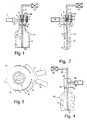
- the device shown in Figure 1 includes a sterilizing agent injector or sprayer 1 vaporizable, such as hydrogen peroxide, acid peracetic, or any other suitable agent.
- the injector is connected on the one hand to an agent reserve, not represented, and to control means for opening and closure, on the other hand.
- the injector can be mechanical, electromechanical, pneumatic or any other suitable type.
- the outlet of the sterilizing liquid from the injector is directed to an evaporator 2 enclosed in a casing 3, cylindrical in the example shown.
- An opening 4 is provided in the cylindrical wall of the casing opposite the outlet of injector 1 to allow spraying of the liquid on the evaporator 2.
- the evaporator 2 is consisting of a cylinder of a good conductive material thermal, and provided, on its periphery, fins 5 in form of annular outgrowths. Preferably, fins are regularly distributed over the height of the cylinder forming the body of the evaporator.
- the outside diameter of the evaporator is less than inside diameter of the casing 3 so that after evaporation, the sterilizer can circulate as it will explained further.
- the casing 3 is closed, at its upper end on the figure, by a cover 6 pierced in its center with a opening for the passage of a sliding hollow tube 7.
- the tube 7 passes through an axial hole, not referenced, of the evaporator 2.
- the lower end of the housing is intended to be located opposite the opening 8 of the hollow body 9 (here a container such as a bottle) to be sterilized. She is open and preferably the shape and dimensions interior of the end opening match respectively to those of the interior opening of the body hollow.
- the evaporator 2 is held in place in the casing 3 at using fixing means 10 such as screws or spacers arranged near the end of the evaporator furthest from the hollow body 9, so as not to not interfere with the path of the evaporated agent between the evaporator 2 and the hollow body 9.
- Heating means 11 of the evaporator 2 are provided to bring it to a temperature allowing to evaporate almost instantly the sterilant when it comes to his contact.
- these means 11 are constituted by a heating resistor arranged in the thickness of the wall of the casing 3, so as to heat up the latter and to reheat the evaporator 2 by conduction thermal through the material of the casing 3 and evaporator 2 and / or by convection in free space between the inner wall of the casing 3 and the evaporator 2.
- the tube 7 is sliding (double arrow 12) to facilitate the positioning of the hollow body 9 next to the device.
- the hollow body 9 can be brought next to the device by simple translation lateral by erasing the tube from the body supply path hollow. It is thus possible to use, to ensure the installation of the hollow body, transfer systems known per se, such as gripper mechanisms transfer, mounted on articulated arms, or wheeled mechanisms or transfer trays comprising notches or cavities for guiding the hollow bodies.
- the implementation place of the hollow body is effected by subjecting it to a axial translation, the tube 7 remaining fixed.
- only the tube 7 is sliding. he therefore slides relative to the hollow body, and to the assembly consisting of the evaporator 2 and the casing 3 during the placement or removal of the hollow body.
- the end of the tube 7 located on the side of the cover 6 of the casing 3 is connected to a suction source 13.
- a suction source 13 When the hollow body 9 is in place, as illustrated in the figure 1, the end of the tube opening into the hollow body 9 is near the bottom 14 of the latter.
- the operation of the device is as follows.
- the evaporator 2 is heated by means heating 11, so that its temperature is sufficient to cause immediate evaporation of the sterilizing agent when the latter, projected by the injector 1, comes into contact with it.
- evaporator 2 when the agent is peroxide of hydrogen, evaporator 2 is brought to a temperature between 100 ° C and 400 ° C, preferably of the order of 150-200 ° C.
- the opening 8 of the hollow body 9 is placed opposite the opening of the casing, without however coming into contact with it, so that a draft can be created between the opening 4 of housing 3 and the gap remaining between the container and the housing.
- the fact of maintaining a spacing between the casing and the hollow body prevents deterioration of this the latter when made of heat-sensitive material.
- the device is kept in an ambience sterile overpressure air to prevent particles or additional dust does not enter the body hollow to sterilize.
- known means are used, such as a flow isolation chamber laminar sterile air in which the device.
- the sterilizing agent is sprayed or injected by the injector or sprayer 1 on the evaporator 2 at through orifice 4 formed in the casing 3.
- the upper temperature of evaporator 2 causes vaporization sterilizing agent, and the suction generated by the means 13 through the tube 7 opening at proximity of the bottom 14 of the hollow body 9 creates a current entrainment of the air contained in the hollow body, followed entrainment of the vapors of the sterilizing agent which are then directed inside the hollow body 9 and are deposited on the internal surface of the hollow body.
- This current is shown diagrammatically by the arrows 15 in the figure.
- the sterilizing agent condenses on contacting the internal surface of the hollow body.
- the sterilizing agent contained in the hollow body is removed.
- Tests carried out on container preforms in plastic (PET) or on the containers themselves show that a contact time between 2 and 6 seconds provides a compatible degree of aseptic with current food standards using as concentrated hydrogen peroxide sterilizer 35%.
- the suction through the tube 7 can be permanent or sequential. If it is sequential, it is against important that it starts no later than the injection so that all the sterilant injected and vaporized is sucked towards the hollow body. A consequence of an aspiration starting with a slight delay on the injection would be the risk of losing some amount of agent, by evaporation to the outside, in particular through port 4. This risk of loss no longer exists if aspiration begins at the time of injection.
- the hollow body is sterile.
- the agent should be removed sterilizing, for example by drying the hollow body when the agent is liquid.
- blow a gas sterile such as dry or hot sterile air in the body preferably be to cause hot air to the interior of the hollow body by suction.
- blowing hot air is difficult in the case of hollow body having a particular geometry, for example in the case of bottles where the air flow is directed preferentially towards the bottom, but does not come to the contact of all the walls.
- an advantage of the solution consisting of entraining hot air is that it is possible to use the same device as that used for vaporization and deposition of sterilizing agent, replacing the injector 1 a heat generator 16 as shown in the Figure 2 (not according to claim 14).
- the heat generator 16 can be a high temperature hot air nozzle or a burner. Heat or flame is directed to the orifice 4 and simultaneously an aspiration is created in the body hollow (here a container preform) to channel the flame or heat towards the walls.
- thermoplastic material such as containers or container preforms of thermoplastic material.
- the time of exposure to heat is very low.
- the directed hot air has only a purge function or for drying the hollow body.
- the hollow body to be sterilized is in thermoplastic material, it is preferable to provide means to prevent a direct transfer between the exit of the heat generator 16 and the exterior of the hollow body 9.
- These means can be constituted by a plate 17 of protection of the opening of the surrounding hollow body at least partially the casing 3 and disposed between the orifice 4 of passage of hot air from the flame and opening of the casing 3 on the hollow body side 9, as visible in FIG. 2.
- a shaped cap could be provided. of cloches covering more widely the opening of the body hollow.
- Figure 3 there is shown schematically, in view cut from above at orifice 4, an arrangement possible of a single device used both for filing sterilizing and drying agent.
- Both the output of an injector 1 and that of a hot air generator 16 are directed towards the orifice 4 of the casing 3.
- the air generator 16 must be is of the sequential type so that the heat (flame or hot air) is not applied during the phases agent / spray / contact agent sterilization.
- the drying phase of the hollow body is carried out in two stages: a first where the heat (flame or hot air) is applied in the housing, the suction being active; and a second or the aspiration continues when heat is no longer applied, so that all vapor residue is removed.
- the heat flame or hot air
- the suction being active
- the aspiration continues when heat is no longer applied, so that all vapor residue is removed.
- thermoplastic containers we manage to dry out preforms of thermoplastic containers by applying a flame for 1 to 3 seconds at port 4 and continuing the suction between 2 and 6 seconds.
- a casing 18 in the form of a closed cylindrical tube 19 at one end and open at the other.
- the housing is pierced with an orifice 20 opposite which is a heat generator 21, a burner in the example.
- a hollow rod 22 passes through the casing so that one 23 of its ends is near the bottom of the body hollow 24.
- the other end of the rod is connected to a suction device 25.
- a flame 26 When the heat, here a flame 26, is applied in at the same time as the suction, a flow is created (arrows 27) sucking up the flame and the vapors of sterilizing agent and drying the inner surface of the hollow body.
- the agent injection / vaporization phase is preceded by a phase of removal of the hollow body from particles such as dust or other elements not members.
- This phase can be performed by aspiration and / or blowing or any other suitable method.
- a similar device is used to that used for the removal of traces of agent sterilant and presented in Figure 4 with the difference that the device does not include an air generator hot.
- the device therefore includes suction means 22,23,25 and a housing 18.
- the withdrawal phase prior to agent injection no longer by sucking on the rod 22, but by sucking on the casing 18, for example via the orifice 20.
- the rod 22 allows the air to compensate for the depression created during aspiration.
- all of the phases mentioned above is performed on a single device, such as that presented in FIG. 3, and therefore comprising a evaporator, suction means, means agent injection and a hot air generator, i.e. all the means presented in more detail on the Figures 1,2 and 4.
- the first phase consists in recovering dust or other particles, while following, it is gases or vapors which are sucked up.
- the dust or other particles must be collected and discarded while agent gases or vapors sterilant can be recycled. So if we want organize a recycling of vapors or gases, it is necessary to have separate suction means, and there it is desirable to differentiate the respective devices.
- the use of a single device is not adapted when the device must have cadences high, for example when the hollow bodies to be sterilized are preforms of containers (bottles or others) in plastic material, brought to the parade at the entrance of a blowing machine for containers, or containers for exit from manufacturing.
- Figure 5 illustrates the block diagram of a installation allowing to carry out all the phases mentioned above during the processing of preforms 28 in view of their sterilization upstream of a machine 29 of blowing / filling of containers 30.
- the preforms 28, continuously scrolling in the direction of arrows 31 are successively brought in a first stage 32 of withdrawal (dusting or other).
- This floor includes means, not shown, for processing parade several preforms.
- This floor has one or more device (s) in accordance with that of FIG. 1.
- the preforms are transferred to a stage 34 of drying. It should be noted that the transfer time between the previous state and the latter is used to extend the contact time required to sterilization.
- the preforms are transferred to the machine 29 of manufacture / filling of containers.
- the machine 29 and the various stages of treatment 32,33,34 are enclosed in a sterile enclosure under laminar flow.
- Each of the processing stages, respectively 32,33,34 may include at least one suitable fixed device before which the hollow bodies are brought in step by step view of their treatment.
- each floor is arranged to allow treatment at the parade of hollow body.
- each stage comprises means for gripping or supporting hollow bodies, associated with continuous means of transport. It is thus possible to treat hollow bodies as they arrive in the installation.
- the processing rate depends on the dimensioning of each stage and therefore the number of devices that each one incorporates.
- the phases of sterilization takes place after the manufacture of containers, for example before filling.
- the various stages, in particular that 33 for proper sterilization said, are then downstream of the output of the machine 29.
- the machine 29 may not be under flux sterile air light fixture; but it is important that at least the sterilization and drying stages 33, 34 are, as for them, under luminous flux.
- FIG. 6 a diagram of the principle of "the invention, when applied to sterilization of hollow bodies open at two of their ends. It is for example the case of various tubes or conduits.
- aspiration is carried out not using of a tube passing through the casing 36, and opening at the end 37 of the hollow body 38 opposite that 39 near which is the housing 36 with the injection means (not shown) and / or the air generation means hot (not shown), but it is performed using a tube 40 located at the open end 37 of the hollow body opposite to that 39 near which the housing 36 is located.
- the tube 40 is connected to suction means 41.
Landscapes
- Health & Medical Sciences (AREA)
- Chemical & Material Sciences (AREA)
- Life Sciences & Earth Sciences (AREA)
- Engineering & Computer Science (AREA)
- Chemical Kinetics & Catalysis (AREA)
- General Chemical & Material Sciences (AREA)
- Manufacturing & Machinery (AREA)
- Epidemiology (AREA)
- Mechanical Engineering (AREA)
- Animal Behavior & Ethology (AREA)
- General Health & Medical Sciences (AREA)
- Public Health (AREA)
- Veterinary Medicine (AREA)
- Apparatus For Disinfection Or Sterilisation (AREA)
- External Artificial Organs (AREA)
Claims (30)
- Verfahren zur Sterilisation von Hohlkörpern (9) mit einer Öffnung (8) jener Art, bei der man auf die zu sterilisierenden Flächen ein zuvor verdampftes Sterilisationsmittel aufbringt, dadurch gekennzeichnet, daß man die Verdampfung des Mittels außerhalb des Hohlkörpers in der Nähe seiner Öffnung durchführt und mit Hilfe von im Hohlkörper gegenüber der Öffnung mündenden Saugvorrichtungen einen Gasstrom zur Mitführung des verdampften Mittels zu allen zu sterilisierenden Flächen erzeugt, um das Mittel auf die gesamten Flächen zu verteilen.
- Verfahren zur Sterilisation von Hohlkörpern (38) mit zwei Öffnungen jener Art, bei der man auf die zu sterilisierenden Flächen ein zuvor verdampftes Sterilisationsmittel aufbringt, dadurch gekennzeichnet, daß man die Verdampfung des Mittels außerhalb des Hohlkörpers in der Nähe einer seiner Öffnungen durchführt und mit Hilfe von im Hohlkörper gegenüber der Öffnung mündenden Saugvorrichtungen einen Gasstrom zur Mitführung des verdampften Mittels zu allen zu sterilisierenden Flächen erzeugt, um das Mittel auf die gesamten Flächen zu verteilen.
- Verfahren nach einem der vorhergehenden Ansprüche, dadurch gekennzeichnet, daß das Sterilisationsmittel unter in flüssiger Phase verfügbaren Mitteln, wie zum Beispiel Wasserstoffperoxid, Peressigsäure und dergleichen, ausgewählt wird.
- Verfahren nach einem der vorhergehenden Ansprüche, dadurch gekennzeichnet, daß eine Phase der Entfernung der im Hohlkörper vorhandenen, nicht adhärenten Teilchen oder anderen Elemente der Verdampfungs- und Einführungsphase des Mittels in den Hohlkörper vorausgeht.
- Verfahren nach Anspruch 4, dadurch gekennzeichnet, daß die Entfernungsphase durch Blasen durchgeführt wird.
- Verfahren nach Anspruch 4, dadurch gekennzeichnet, daß die Entfernungsphase durch Saugen durchgeführt wird.
- Verfahren nach einem der vorhergehenden Ansprüche, dadurch gekennzeichnet, daß der Verdampfungsphase nach einer Kontaktzeit des Mittels mit den zu sterilisierenden Flächen eine Phase des Abziehens des verbleibenden Sterilisationsmittels folgt.
- Verfahren nach Anspruch 7, dadurch gekennzeichnet, daß die Abziehphase durch Injizieren eines Abziehmittels in den Innenraum des Hohlkörpers durchgeführt wird.
- Verfahren nach Anspruch 8, dadurch gekennzeichnet, daß das Abziehmittel ein steriles Trocken- oder Heißgas ist.
- Verfahren nach Anspruch 9, dadurch gekennzeichnet, daß das Abziehmittel durch Saugen in den Innenraum des Hohlkörpers mittels im Hohlkörper gegenüber seiner Öffnung wirkenden Saugvorrichtungen mitgeführt wird.
- Verfahren nach Anspruch 8 oder 9, dadurch gekennzeichnet, daß das sterile Gas mittels einer Heißluftdüse injizierte Heißluft ist.
- Verfahren nach Anspruch 8, dadurch gekennzeichnet, daß die Abziehphase mittels einer von einem Brenner injizierten und durch Saugen in den Innenraum des Hohlkörpers mit Hilfe von gegenüber seiner Öffnung darin wirkenden Saugvorrichtungen mitgeführten Flamme durchgeführt wird.
- Verfahren nach einem der Ansprüche 8 bis 12, dadurch gekennzeichnet, daß das Abziehmittel, das Trocken- oder Heißgas bzw. die Flamme auf die Außenseite des Hohlkörpers in der Nähe seiner Öffnung injiziert wird.
- Einrichtung zur Durchführung des Verfahren nach einem der Ansprüche 1 bis 13, dadurch gekennzeichnet, daß sie folgendes umfaßt: Vorrichtungen (1) zur Injektion eines verdampfbaren Sterilisationsmittels, einen Verdampfer (2) gegenüber dem Ausgang der Injektionsvorrichtungen, Mittel zur Erzeugung einer Relativbewegung der Saugvorrichtungen (7, 13; 40, 41) und des Hohlkörpers derart, daß die Saugvorrichtungen im Hohlkörper münden und so darin wirken können, um einen Gasstrom zur Mitführung des verdampften Mittels zu den Innenflächen eines Hohlkörpers (9; 38) zu erzeugen, wenn dieser bezüglich der Einrichtung in Position ist.
- Einrichtung nach Anspruch 14, dadurch gekennzeichnet, daß der Verdampfer in einem Gehäuse (3; 36) eingeschlossen ist, das außerhalb des Hohlkörpers (9; 38) in der Nähe der Öffnung des letzteren angeordnet ist, und mit folgendem versehen ist: einer Öffnung (4) gegenüber dem Ausgang der Injektionsvorrichtungen (1); einem offenen Ende, dessen Form und Innenabmessungen denen der inneren Öffnung des Hohlkörpers (9; 38) im wesentlichen entsprechen.
- Einrichtung nach Anspruch 14 oder 15, dadurch gekennzeichnet, daß die Vorrichtungen (7; 13; 40, 41) zur Erzeugung des Gasstroms aus einem mit einer Saugquelle (13; 41) verbundenen Rohr (7; 40) bestehen.
- Einrichtung nach Anspruch 16, dadurch gekennzeichnet, daß aufgrund der Ausbildung des Hohlkörpers in Form eines Behälters, wobei er somit an einem seiner Enden offen und am anderen geschlossen ist, das Rohr (7) durch die Öffnung des Hohlkörpers eingeführt wird, wobei es ein in der Nähe des Hohlkörperbodens mündendes Ende aufweist und sein zweites, sich auf der Seite des Gehäuses (3) befindendes Ende mit der Saugquelle (13) verbunden ist.
- Einrichtung nach Anspruch 17, dadurch gekennzeichnet, daß das Rohr (7) den Verdampfer (2) und das Gehäuse (3) durchquert.
- Einrichtung nach Anspruch 16, dadurch gekennzeichnet, daß aufgrund der Ausbildung des Hohlkörpers (38) als ein an zwei gegenüberliegenden Enden offenes Rohr oder eine solche Leitung das Saugen durch Anordnung des Saugrohrs (40) an dem Hohlkörperende, das dem Ende, an dem das Injizieren erfolgt, gegenüberliegt, durchgeführt wird.
- Einrichtung nach einem der Ansprüche 14 bis 19, dadurch gekennzeichnet, daß sie Vorrichtungen zum Abziehen des Sterilisationsmittels nach einer Kontaktzeit im Hohlkörper aufweist.
- Einrichtung nach Anspruch 20, dadurch gekennzeichnet, daß die Vorrichtungen einen Generator (16; 21) für steriles Trocken- oder Heißgas enthalten.
- Einrichtung nach Anspruch 21, dadurch gekennzeichnet, daß der Generator ein Brenner (21) ist.
- Einrichtung nach Anspruch 21 oder 22, dadurch gekennzeichnet, daß der Generator (15; 21) außerhalb des Hohlkörpers in der Nähe seiner Öffnung angeordnet ist und Vorrichtungen zum Leiten der Wärme in den Innenraum des Hohlkörpers enthält.
- Einrichtung nach Anspruch 23, dadurch gekennzeichnet, daß die Wärmeleitvorrichtungen aus dem Saugrohr (7; 22; 40) bestehen, dessen Saugende im Hohlkörper in einen von seiner Öffnung entfernten Bereich mündet, um die Wärme in den gesamten Hohlkörper mitzuführen.
- Einrichtung nach Anspruch 24, dadurch gekennzeichnet, daß der Hohlkörper ein Behälter ist und das Rohr (7; 22) durch die Öffnung des letzteren eintritt und in der Nähe seines Bodens mündet.
- Einrichtung nach Anspruch 24, dadurch gekennzeichnet, daß der Hohlkörper ein Rohr oder eine Leitung ist und das Rohr (40) an dem Ende des Hohlkörpers angeordnet ist, das dem gegenüberliegt, in dessen Nähe sich der Wärmegenerator (16; 21) befindet.
- Einrichtung nach einem der Ansprüche 14 bis 26, dadurch gekennzeichnet, daß sie Mittel zur Durchführung einer Entfernung von Staub- oder anderen Teilchen vor der Verdampfungsphase und zur Einbringung des Sterilisationsmittels enthält.
- Einrichtung nach Anspruch 27, dadurch gekennzeichnet, daß die Entfernung durch Saugen und/oder Blasen erfolgt.
- Einrichtung nach einem der Ansprüche 14 bis 28, dadurch gekennzeichnet, daß sie von einer mit Überdruck beaufschlagten Laminarströmung (35) aus sterilem Gas, wie zum Beispiel Luft, durchströmt werden kann.
- Anlage zur Herstellung und/oder Füllung von Behältern, dadurch gekennzeichnet, daß sie eine Einrichtung nach einem der Ansprüche 14 bis 29 aufweist.
Applications Claiming Priority (3)
| Application Number | Priority Date | Filing Date | Title |
|---|---|---|---|
| FR9801937 | 1998-02-16 | ||
| FR9801937A FR2774912B1 (fr) | 1998-02-16 | 1998-02-16 | Procede pour steriliser des corps creux et dispositif pour la mise en oeuvre |
| PCT/FR1999/000253 WO1999040949A1 (fr) | 1998-02-16 | 1999-02-04 | Procede et dispositif pour la sterilisation des corps creux |
Publications (2)
| Publication Number | Publication Date |
|---|---|
| EP1056481A1 EP1056481A1 (de) | 2000-12-06 |
| EP1056481B1 true EP1056481B1 (de) | 2001-10-24 |
Family
ID=9523086
Family Applications (1)
| Application Number | Title | Priority Date | Filing Date |
|---|---|---|---|
| EP99903726A Expired - Lifetime EP1056481B1 (de) | 1998-02-16 | 1999-02-04 | Verfahren und anordnung zur sterilisation von hohlkörpern |
Country Status (9)
| Country | Link |
|---|---|
| US (1) | US6984360B1 (de) |
| EP (1) | EP1056481B1 (de) |
| JP (1) | JP3780165B2 (de) |
| AT (1) | ATE207368T1 (de) |
| AU (1) | AU2428499A (de) |
| DE (1) | DE69900390T2 (de) |
| ES (1) | ES2166638T3 (de) |
| FR (1) | FR2774912B1 (de) |
| WO (1) | WO1999040949A1 (de) |
Cited By (2)
| Publication number | Priority date | Publication date | Assignee | Title |
|---|---|---|---|---|
| DE102008056346A1 (de) | 2008-11-07 | 2010-05-12 | Krones Ag | Verfahren zur Vorbehandlung von Vorformlingen und Streckblasmaschine zur Vorbehandlung und zum Streckblasen von Vorformlingen zu Behältern |
| US11147894B2 (en) | 2007-11-19 | 2021-10-19 | Sidel Participations | Device for transporting a hollow body, installation provided with such devices, and method for conveying a hollow body attached to such a device |
Families Citing this family (34)
| Publication number | Priority date | Publication date | Assignee | Title |
|---|---|---|---|---|
| DE19956186A1 (de) * | 1999-11-22 | 2001-05-23 | Krones Ag | Verfahren und Vorrichtung zum Sterilisieren von Verpackungsbehältern |
| DE60204543T2 (de) | 2001-02-16 | 2006-05-11 | Steris Inc., Temecula | Dekontamination von behältern mit dampf |
| DE102005012507A1 (de) * | 2005-03-16 | 2006-09-21 | Krones Ag | Verfahren und Vorrichtung betrefffend das Sterilabfüllen von Flüssigkeiten |
| FR2887526B1 (fr) * | 2005-06-24 | 2007-09-07 | Sidel Sas | Procede de sterilisation de preformes et installation produisant des bouteilles steriles a partir de ces preformes |
| FR2887525B1 (fr) * | 2005-06-24 | 2007-09-07 | Sidel Sas | Installation produisant des bouteilles steriles par soufflage a partir de preformes sterilisees |
| SE528990C8 (sv) * | 2005-08-23 | 2007-05-08 | Tetra Laval Holdings & Finance | Sätt och anordning för sterilisering av förpackningsämnen |
| SE528989C8 (sv) * | 2005-08-23 | 2007-05-08 | Tetra Laval Holdings & Finance | Sätt och anordning för sterilisering av förpackningsämnen |
| AU2007215373B2 (en) * | 2006-02-09 | 2009-04-02 | P.H.E. Enterprises Pty Ltd | A heating assembly |
| WO2008022290A1 (en) * | 2006-08-17 | 2008-02-21 | University Of Washington | Automated workstation for disinfecting objects and methods of use thereof |
| FR2910329B1 (fr) | 2006-12-20 | 2009-04-17 | Sidel Participations | Procede et dispositif de sterilisation de preformes |
| WO2009142198A1 (ja) * | 2008-05-20 | 2009-11-26 | 大日本印刷株式会社 | 飲料充填方法及び装置 |
| DE102008037708B4 (de) | 2008-08-14 | 2014-05-28 | Krones Aktiengesellschaft | Verfahren und Vorrichtung zum Behandeln von Getränkebehältnissen |
| DE102008038143A1 (de) * | 2008-08-18 | 2010-02-25 | Krones Ag | Vorrichtung zum Sterilisieren von Kunststoffvorformlingen |
| CN104944345B (zh) * | 2009-02-06 | 2017-09-29 | 大日本印刷株式会社 | 饮料灌装方法及饮料灌装装置 |
| DE102009061262B3 (de) | 2009-08-11 | 2020-06-25 | Krones Aktiengesellschaft | Blasformmaschine mit Reinigungssystem |
| DE102009036922A1 (de) | 2009-08-11 | 2011-02-17 | Krones Ag | Blasformmaschine mit Reinigungssystem |
| JP5831673B2 (ja) * | 2010-01-22 | 2015-12-09 | 東洋製罐株式会社 | 空間表面の殺菌方法 |
| FR2961125B1 (fr) | 2010-06-10 | 2012-07-13 | Sidel Participations | Procede de recyclage d'air comportant un agent sterilisant et installation de fabrication de recipients comportant un circuit de recyclage d'air |
| DE102010026166A1 (de) * | 2010-07-01 | 2012-01-05 | Khs Corpoplast Gmbh | Verfahren und Vorrichtung zum Sterilisieren sowie Vorrichtung zur Blasformung von Behältern |
| DE102011104024A1 (de) | 2011-06-06 | 2012-12-06 | Khs Corpoplast Gmbh | Verfahren und Vorrichtung zum Sterilisieren sowie Vorrichtung zur Blasformung von Behältern |
| WO2013138324A2 (en) * | 2012-03-13 | 2013-09-19 | Fmc Corporation | Improved sterilization method |
| JP5962352B2 (ja) * | 2012-09-05 | 2016-08-03 | 大日本印刷株式会社 | プリフォーム殺菌方法並びに内容物充填方法及び装置 |
| JP6044088B2 (ja) * | 2012-03-14 | 2016-12-14 | 大日本印刷株式会社 | プリフォーム殺菌方法並びに内容物充填方法及び装置 |
| CN104169176B (zh) * | 2012-03-14 | 2017-04-12 | 大日本印刷株式会社 | 预成型坯的杀菌方法以及内容物的充填方法及装置 |
| ITPR20120048A1 (it) * | 2012-07-25 | 2014-01-26 | Gea Procomac Spa | Metodo e apparato di formatura di un contenitore |
| DE102013101642A1 (de) * | 2013-02-19 | 2014-08-21 | Khs Gmbh | Verfahren und Vorrichtung zum Herstellen und Füllen von Behältern |
| JP6144935B2 (ja) | 2013-03-18 | 2017-06-07 | 三菱重工メカトロシステムズ株式会社 | 容器の殺菌装置 |
| DE102013106694A1 (de) * | 2013-06-26 | 2015-01-15 | Krones Ag | Verfahren und Vorrichtung zum Umformen von Kunststoffvorformlingen zu Kunststoffbehältnissen |
| JP6439920B2 (ja) * | 2013-11-14 | 2018-12-19 | 大日本印刷株式会社 | ボトルの殺菌方法及び装置 |
| FR3014352B1 (fr) * | 2013-12-09 | 2016-01-22 | Sidel Participations | Dispositif de traitement en serie de corps creux comportant une tige de traitement commandee en coulissement par un actionneur electrique et procede de traitement |
| US10343907B2 (en) * | 2014-03-28 | 2019-07-09 | Asm Ip Holding B.V. | Method and system for delivering hydrogen peroxide to a semiconductor processing chamber |
| JP6397731B2 (ja) * | 2014-11-05 | 2018-09-26 | 株式会社フロンティア | プリフォームの除塵方法および除塵機構、ブロー成形機、並びに容器のブロー成形・充填システム |
| FR3054474B1 (fr) * | 2017-02-16 | 2018-08-17 | Sidel Participations | Dispositif et procede de depoussierage de l'interieur d'au moins une preforme |
| FR3119096B1 (fr) | 2021-01-25 | 2024-01-12 | Claranor | Lampe a introduire dans un objet, notamment pour sa decontamination |
Family Cites Families (5)
| Publication number | Priority date | Publication date | Assignee | Title |
|---|---|---|---|---|
| US3042533A (en) * | 1955-12-06 | 1962-07-03 | John E W Mcconnell | Method of sterilization |
| NL7009539A (de) * | 1969-07-07 | 1971-01-11 | ||
| DE3809852A1 (de) * | 1988-03-24 | 1989-10-05 | Seitz Enzinger Noll Masch | Verfahren zum aseptischen bzw. sterilen abfuellen von fluessigem fuellgut in behaelter sowie vorrichtung zum durchfuehren dieses verfahrens |
| US4992247A (en) * | 1989-05-11 | 1991-02-12 | Elopak Systems, A.G. | Container sterilization system |
| DE4305478A1 (de) * | 1993-02-23 | 1994-08-25 | Tetra Laval Holdings & Finance | Verfahren und Vorrichtung zum Sterilisieren von Packungen |
-
1998
- 1998-02-16 FR FR9801937A patent/FR2774912B1/fr not_active Expired - Fee Related
-
1999
- 1999-02-04 AT AT99903726T patent/ATE207368T1/de not_active IP Right Cessation
- 1999-02-04 DE DE69900390T patent/DE69900390T2/de not_active Expired - Lifetime
- 1999-02-04 WO PCT/FR1999/000253 patent/WO1999040949A1/fr active IP Right Grant
- 1999-02-04 AU AU24284/99A patent/AU2428499A/en not_active Abandoned
- 1999-02-04 ES ES99903726T patent/ES2166638T3/es not_active Expired - Lifetime
- 1999-02-04 US US09/622,359 patent/US6984360B1/en not_active Expired - Fee Related
- 1999-02-04 JP JP2000531200A patent/JP3780165B2/ja not_active Expired - Fee Related
- 1999-02-04 EP EP99903726A patent/EP1056481B1/de not_active Expired - Lifetime
Cited By (3)
| Publication number | Priority date | Publication date | Assignee | Title |
|---|---|---|---|---|
| US11147894B2 (en) | 2007-11-19 | 2021-10-19 | Sidel Participations | Device for transporting a hollow body, installation provided with such devices, and method for conveying a hollow body attached to such a device |
| DE102008056346A1 (de) | 2008-11-07 | 2010-05-12 | Krones Ag | Verfahren zur Vorbehandlung von Vorformlingen und Streckblasmaschine zur Vorbehandlung und zum Streckblasen von Vorformlingen zu Behältern |
| US9272060B2 (en) | 2008-11-07 | 2016-03-01 | Krones Ag | Method for pre-treating preforms and blow molding apparatus for pre-treating and blow molding preforms into containers |
Also Published As
| Publication number | Publication date |
|---|---|
| AU2428499A (en) | 1999-08-30 |
| ATE207368T1 (de) | 2001-11-15 |
| DE69900390D1 (de) | 2001-11-29 |
| JP2002502669A (ja) | 2002-01-29 |
| DE69900390T2 (de) | 2002-06-27 |
| WO1999040949A1 (fr) | 1999-08-19 |
| FR2774912A1 (fr) | 1999-08-20 |
| EP1056481A1 (de) | 2000-12-06 |
| US6984360B1 (en) | 2006-01-10 |
| JP3780165B2 (ja) | 2006-05-31 |
| FR2774912B1 (fr) | 2000-09-01 |
| ES2166638T3 (es) | 2002-04-16 |
Similar Documents
| Publication | Publication Date | Title |
|---|---|---|
| EP1056481B1 (de) | Verfahren und anordnung zur sterilisation von hohlkörpern | |
| EP1896245B1 (de) | Verfahren zur sterilisation von vorformlingen und anlage zur herstellung von sterilen körpers aus diesen vorformlingen | |
| EP1941913B1 (de) | Verfahren und Vorrichtung zur Sterilisierung von Vorformen | |
| EP1896329B1 (de) | Anlage zur herstellung steriler flaschen durch blasformen sterilisierter vorformen | |
| EP2094312B1 (de) | Ofen und anlage zur herstellung von sterilen gefässen aus dekontaminierten vorformen eines thermoplastischen materials | |
| CA2297260C (fr) | Procede pour la fabrication de recipients steriles en matiere plastique, et installation pour la mise en oeuvre | |
| EP1490265B8 (de) | Verfahren und vorrichtung zur dekontamination von vorformlinghälsen | |
| EP1056980A1 (de) | Verfahren zum trocknen von hohlkörper und vorrichtung zu seiner durchführung | |
| CA2689734A1 (fr) | Procede et installation pour le conditionnement sous vide en continu de produits alimentaires | |
| FR2813196A1 (fr) | Procede de sterilisation d'objets | |
| FR2807912A1 (fr) | Procede et torche a plasma pour traiter une surface dans une cavite, et installation de remplissage bouchage s'y rapportant | |
| JP2019023095A (ja) | キャップの殺菌方法及び殺菌装置 | |
| JP6330857B2 (ja) | プリフォームの殺菌方法及び装置 | |
| WO2017203136A1 (fr) | Procede et installation de fabrication et de traitement de recipients | |
| JP6439946B2 (ja) | プリフォームの殺菌方法及び装置 | |
| EP3551233A2 (de) | Verfahren zur dekontamination einer aussenfläche eines thermoplastischen vorform | |
| JP6614271B2 (ja) | プリフォームの殺菌方法及び装置 | |
| WO2021005144A1 (fr) | Procede de decontamination d'une preforme au moyen d'especes reactives obtenues par melange d'un agent precurseur et d'un plasma | |
| JP6330865B2 (ja) | プリフォームの殺菌方法及び装置 | |
| JP2017226468A (ja) | 紙容器の殺菌方法及び装置 | |
| BE388226A (de) |
Legal Events
| Date | Code | Title | Description |
|---|---|---|---|
| PUAI | Public reference made under article 153(3) epc to a published international application that has entered the european phase |
Free format text: ORIGINAL CODE: 0009012 |
|
| GRAG | Despatch of communication of intention to grant |
Free format text: ORIGINAL CODE: EPIDOS AGRA |
|
| 17P | Request for examination filed |
Effective date: 20000918 |
|
| AK | Designated contracting states |
Kind code of ref document: A1 Designated state(s): AT BE CH DE DK ES FR GB IE IT LI NL SE |
|
| 17Q | First examination report despatched |
Effective date: 20001207 |
|
| GRAG | Despatch of communication of intention to grant |
Free format text: ORIGINAL CODE: EPIDOS AGRA |
|
| GRAH | Despatch of communication of intention to grant a patent |
Free format text: ORIGINAL CODE: EPIDOS IGRA |
|
| GRAH | Despatch of communication of intention to grant a patent |
Free format text: ORIGINAL CODE: EPIDOS IGRA |
|
| GRAA | (expected) grant |
Free format text: ORIGINAL CODE: 0009210 |
|
| AK | Designated contracting states |
Kind code of ref document: B1 Designated state(s): AT BE CH DE DK ES FR GB IE IT LI NL SE |
|
| PG25 | Lapsed in a contracting state [announced via postgrant information from national office to epo] |
Ref country code: NL Free format text: LAPSE BECAUSE OF FAILURE TO SUBMIT A TRANSLATION OF THE DESCRIPTION OR TO PAY THE FEE WITHIN THE PRESCRIBED TIME-LIMIT Effective date: 20011024 Ref country code: IE Free format text: LAPSE BECAUSE OF FAILURE TO SUBMIT A TRANSLATION OF THE DESCRIPTION OR TO PAY THE FEE WITHIN THE PRESCRIBED TIME-LIMIT Effective date: 20011024 Ref country code: AT Free format text: LAPSE BECAUSE OF FAILURE TO SUBMIT A TRANSLATION OF THE DESCRIPTION OR TO PAY THE FEE WITHIN THE PRESCRIBED TIME-LIMIT Effective date: 20011024 |
|
| REF | Corresponds to: |
Ref document number: 207368 Country of ref document: AT Date of ref document: 20011115 Kind code of ref document: T |
|
| REG | Reference to a national code |
Ref country code: CH Ref legal event code: EP |
|
| REG | Reference to a national code |
Ref country code: IE Ref legal event code: FG4D Free format text: FRENCH |
|
| REF | Corresponds to: |
Ref document number: 69900390 Country of ref document: DE Date of ref document: 20011129 |
|
| REG | Reference to a national code |
Ref country code: GB Ref legal event code: IF02 |
|
| PG25 | Lapsed in a contracting state [announced via postgrant information from national office to epo] |
Ref country code: SE Free format text: LAPSE BECAUSE OF FAILURE TO SUBMIT A TRANSLATION OF THE DESCRIPTION OR TO PAY THE FEE WITHIN THE PRESCRIBED TIME-LIMIT Effective date: 20020124 Ref country code: DK Free format text: LAPSE BECAUSE OF FAILURE TO SUBMIT A TRANSLATION OF THE DESCRIPTION OR TO PAY THE FEE WITHIN THE PRESCRIBED TIME-LIMIT Effective date: 20020124 |
|
| GBT | Gb: translation of ep patent filed (gb section 77(6)(a)/1977) |
Effective date: 20020114 |
|
| REG | Reference to a national code |
Ref country code: CH Ref legal event code: NV Representative=s name: KELLER & PARTNER PATENTANWAELTE AG |
|
| NLV1 | Nl: lapsed or annulled due to failure to fulfill the requirements of art. 29p and 29m of the patents act | ||
| REG | Reference to a national code |
Ref country code: ES Ref legal event code: FG2A Ref document number: 2166638 Country of ref document: ES Kind code of ref document: T3 |
|
| REG | Reference to a national code |
Ref country code: IE Ref legal event code: FD4D |
|
| PLBE | No opposition filed within time limit |
Free format text: ORIGINAL CODE: 0009261 |
|
| STAA | Information on the status of an ep patent application or granted ep patent |
Free format text: STATUS: NO OPPOSITION FILED WITHIN TIME LIMIT |
|
| 26N | No opposition filed | ||
| PGFP | Annual fee paid to national office [announced via postgrant information from national office to epo] |
Ref country code: CH Payment date: 20060125 Year of fee payment: 8 |
|
| PGFP | Annual fee paid to national office [announced via postgrant information from national office to epo] |
Ref country code: BE Payment date: 20060126 Year of fee payment: 8 |
|
| PG25 | Lapsed in a contracting state [announced via postgrant information from national office to epo] |
Ref country code: LI Free format text: LAPSE BECAUSE OF NON-PAYMENT OF DUE FEES Effective date: 20070228 Ref country code: CH Free format text: LAPSE BECAUSE OF NON-PAYMENT OF DUE FEES Effective date: 20070228 |
|
| REG | Reference to a national code |
Ref country code: CH Ref legal event code: PL |
|
| BERE | Be: lapsed |
Owner name: S.A. *SIDEL Effective date: 20070228 |
|
| PG25 | Lapsed in a contracting state [announced via postgrant information from national office to epo] |
Ref country code: BE Free format text: LAPSE BECAUSE OF NON-PAYMENT OF DUE FEES Effective date: 20070228 |
|
| REG | Reference to a national code |
Ref country code: FR Ref legal event code: PLFP Year of fee payment: 18 |
|
| PGFP | Annual fee paid to national office [announced via postgrant information from national office to epo] |
Ref country code: DE Payment date: 20160121 Year of fee payment: 18 Ref country code: ES Payment date: 20160205 Year of fee payment: 18 Ref country code: IT Payment date: 20160127 Year of fee payment: 18 |
|
| PGFP | Annual fee paid to national office [announced via postgrant information from national office to epo] |
Ref country code: GB Payment date: 20160127 Year of fee payment: 18 Ref country code: FR Payment date: 20160121 Year of fee payment: 18 |
|
| REG | Reference to a national code |
Ref country code: DE Ref legal event code: R119 Ref document number: 69900390 Country of ref document: DE |
|
| GBPC | Gb: european patent ceased through non-payment of renewal fee |
Effective date: 20170204 |
|
| REG | Reference to a national code |
Ref country code: FR Ref legal event code: ST Effective date: 20171031 |
|
| PG25 | Lapsed in a contracting state [announced via postgrant information from national office to epo] |
Ref country code: DE Free format text: LAPSE BECAUSE OF NON-PAYMENT OF DUE FEES Effective date: 20170901 Ref country code: FR Free format text: LAPSE BECAUSE OF NON-PAYMENT OF DUE FEES Effective date: 20170228 |
|
| PG25 | Lapsed in a contracting state [announced via postgrant information from national office to epo] |
Ref country code: IT Free format text: LAPSE BECAUSE OF NON-PAYMENT OF DUE FEES Effective date: 20170204 Ref country code: GB Free format text: LAPSE BECAUSE OF NON-PAYMENT OF DUE FEES Effective date: 20170204 |
|
| REG | Reference to a national code |
Ref country code: ES Ref legal event code: FD2A Effective date: 20180507 |
|
| PG25 | Lapsed in a contracting state [announced via postgrant information from national office to epo] |
Ref country code: ES Free format text: LAPSE BECAUSE OF NON-PAYMENT OF DUE FEES Effective date: 20170205 |