EP1050677A2 - Verfahren zum Herstellen eines geteilten Maschinengehäuses - Google Patents
Verfahren zum Herstellen eines geteilten Maschinengehäuses Download PDFInfo
- Publication number
- EP1050677A2 EP1050677A2 EP00107622A EP00107622A EP1050677A2 EP 1050677 A2 EP1050677 A2 EP 1050677A2 EP 00107622 A EP00107622 A EP 00107622A EP 00107622 A EP00107622 A EP 00107622A EP 1050677 A2 EP1050677 A2 EP 1050677A2
- Authority
- EP
- European Patent Office
- Prior art keywords
- machine housing
- shaft
- groove
- sealing ring
- housing parts
- Prior art date
- Legal status (The legal status is an assumption and is not a legal conclusion. Google has not performed a legal analysis and makes no representation as to the accuracy of the status listed.)
- Granted
Links
Images

Classifications
-
- F—MECHANICAL ENGINEERING; LIGHTING; HEATING; WEAPONS; BLASTING
- F02—COMBUSTION ENGINES; HOT-GAS OR COMBUSTION-PRODUCT ENGINE PLANTS
- F02F—CYLINDERS, PISTONS OR CASINGS, FOR COMBUSTION ENGINES; ARRANGEMENTS OF SEALINGS IN COMBUSTION ENGINES
- F02F7/00—Casings, e.g. crankcases
- F02F7/0043—Arrangements of mechanical drive elements
- F02F7/0053—Crankshaft bearings fitted in the crankcase
-
- F—MECHANICAL ENGINEERING; LIGHTING; HEATING; WEAPONS; BLASTING
- F02—COMBUSTION ENGINES; HOT-GAS OR COMBUSTION-PRODUCT ENGINE PLANTS
- F02B—INTERNAL-COMBUSTION PISTON ENGINES; COMBUSTION ENGINES IN GENERAL
- F02B77/00—Component parts, details or accessories, not otherwise provided for
-
- F—MECHANICAL ENGINEERING; LIGHTING; HEATING; WEAPONS; BLASTING
- F02—COMBUSTION ENGINES; HOT-GAS OR COMBUSTION-PRODUCT ENGINE PLANTS
- F02F—CYLINDERS, PISTONS OR CASINGS, FOR COMBUSTION ENGINES; ARRANGEMENTS OF SEALINGS IN COMBUSTION ENGINES
- F02F11/00—Arrangements of sealings in combustion engines
-
- F—MECHANICAL ENGINEERING; LIGHTING; HEATING; WEAPONS; BLASTING
- F02—COMBUSTION ENGINES; HOT-GAS OR COMBUSTION-PRODUCT ENGINE PLANTS
- F02F—CYLINDERS, PISTONS OR CASINGS, FOR COMBUSTION ENGINES; ARRANGEMENTS OF SEALINGS IN COMBUSTION ENGINES
- F02F7/00—Casings, e.g. crankcases
- F02F7/0065—Shape of casings for other machine parts and purposes, e.g. utilisation purposes, safety
- F02F7/008—Sound insulation
Definitions
- the invention relates to a method for producing a split machine housing, which has split bearings in the parting plane for a shaft to be used, in particular a crankcase split in the plane of the crankshaft of an internal combustion engine, the machine housing parts being assembled first and the bearing points being processed and then the Machine housing parts are separated from each other and the shaft is inserted, after which the machine housing is assembled with the provision of a seal in the parting plane.
- a method forms at least the internal state of the art; with regard to the technical environment, reference is also made to DE 196 32 275 A1 or EP 0 408 317 A2.
- the invention relates to a divided machine housing, which is designed with regard to the manufacturing method according to claim 1, and in which at least on one of the end faces a shaft sealing ring is inserted, through which the shaft is guided to the outside.
- a shaft sealing ring is inserted, through which the shaft is guided to the outside.
- the sealing between at least two of each other adjacent components around a technically demanding area because on the one hand a sufficient tightness must be guaranteed, and there on the other hand, the effort to produce this tightness can be optimized should, i.e. should be as low as possible.
- the seal between housing parts is only for example called an internal combustion engine, so especially in the division level a crankcase of an internal combustion engine divided in the plane of the crankshaft.
- liquid sealants are also known, i.e. initially flowable Sealants (e.g. elastomers) that virtually harden after application however, maintain some elasticity.
- initially flowable Sealants e.g. elastomers
- the above DE 195 28 379 C1 a first example, the liquid sealant initially in one of the components to be connected later (or in a groove the same) is introduced, and this initially flowing sealant first solidifies before the components to be connected to each other be added.
- a second example of a liquid sealant is also described at the beginning mentioned EP 0 408 317 A2. Accordingly, one in the parting line between two housing parts in a groove provided in the same in the assembled Condition of these housing parts is initially flowable Injected sealant, which then hardens. That relative to this a particularly reliable seal can be easily achieved if only a sufficient amount of sealant is introduced into said groove is obvious.
- DE 196 32 275 A1 describes such a sealing method in further detail described.
- this machine housing consists of two housing parts (in particular, it is a crankcase upper part and a as Bedplate "designated crankcase lower part of an internal combustion engine, which accommodates the internal combustion engine crankshaft between them) is first assembled without the interposition of a seal in the parting plane.
- the honing tool is inserted into the machine housing in the direction of the longitudinal axis of the crankshaft to be used later, after which the machine housing parts are separated from each other and bearing shells and in particular the (crank) shaft are inserted into the bearing points a liquid sealant is applied to the two machine housing parts, after which the machine housing is assembled.
- this known machining or manufacturing method cannot completely satisfy than by the applied sealant the surface pairing between the housing parts compared to the first assembly is slightly changed for the processing of the bearing points, i.e. the two housing parts (of the crankcase) are in the second assembly with inserted (crank) shaft due to the applied sealant slightly different from each other than when first assembled or when editing the bearings. Furthermore, the one to be waited Hardening process of the initially applied in a flowable state Liquid sealant an undesirable interruption in the entire manufacturing process represents.
- FIG. 1 shows, in a highly abstracted schematic diagram, a central longitudinal section through a divided machine housing with split bearing points provided in the division plane for a shaft to be used.
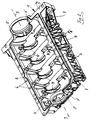
- FIG. 2 the lower part of the machine housing is shown in perspective; furthermore, the partial cross-section AA shown in FIG. 3 in a highly simplified manner is identified here by the assembled machine housing.
- a shaft sealing ring to be inserted into the end face of this machine housing is shown in perspective in FIG. 4 in the form of a first exemplary embodiment.
- the same components are designated with the same reference numbers.
- the reference number 1 denotes the crankcase lower part and reference number 2 the crankcase upper part of a crankcase of a reciprocating piston internal combustion engine divided in the (horizontal) parting plane 3.
- These two crankcase parts 1, 2 are also generally referred to here as machine housing parts 1, 2, since the method described and the corresponding housing design can generally be transferred to any divided machine housing.
- divided bearing points 4 are provided in the parting plane 3 for a shaft to be used, which is not shown in the figure for the sake of simplicity. In the preferred application, this shaft is the crankshaft of the internal combustion engine.
- the bearing points 4 provided in the two machine housing parts 1, 2 must be machined together as part of the manufacturing process of this machine housing, for which purpose the two machine housing parts 1, 2 are first assembled without the use of plain bearing shells and without an inserted (crank) shaft, as in Fig.1 shown.
- the so-called separating flange 2a of the crankcase upper part 2 lying in the division plane 3 is placed on the corresponding so-called separating flange 1a of the crankcase lower part 1, and without a seal in between.
- the two machine housing parts 1, 2 are screwed together, specifically via the screw holes 6 provided several times in the separating flanges 1a, 2a.
- the machining of the bearing points 4 then takes place, as already briefly described at the beginning.
- a groove 7 is provided in at least one of the machine housing parts 1, 2, namely here in the crankcase lower part 1 in the separating flange 1a of the same, which extends virtually all the way over the entire area of this separating flange 1a.
- a liquid sealant can be introduced into this groove 7 via two injection holes 8 which branch off from this groove 7 and are provided on the two longitudinal sides of the machine housing part 1 in approximately the middle thereof and open on the outside thereof, namely after the two machine housing parts 1, 2 were composed.
- FIG. 3 in which a partial cross section or the section AA from FIG. 2 through the assembled machine housing in the region of an injection bore 8 is shown in a greatly simplified manner.
- this groove 7 provided in the separating flange 1a thus forms a channel with a closed cross-section for receiving the liquid sealant, which thus (after hardening) ensures an optimal seal in the dividing plane 3.
- the two machine housing parts 1, 2 are first assembled and screwed together as shown in FIG . 1 (via the screw holes 6 already mentioned), before a liquid sealant which is initially flowable and later substantially curing, but which nevertheless maintains a certain elasticity, is then injected into the groove 7 via the injection bores 8. If it is ensured that this groove 7 is completely filled with the liquid sealant, this results in an optimal seal without - as described at the beginning - the position of the two machine housing parts 1, 2 deviating from one another from the initial assembly for processing the positions 4 .
- a groove in the shaft sealing ring can be formed all around on the outside. It is particularly advantageous if this circumferential groove extends helically when viewed in the direction of the shaft axis 9. If the liquid sealant flows - referring to FIG. 2 - coming from the right-hand groove (provided in the separating flange 1a) into this helically circumferential groove in the shaft seal ring 5, this liquid sealant virtually encircles the shaft seal ring 5 and then reaches the opposite left-hand side (in the separating flange 1a provided) groove 7.
- the initially flowable and later curing sealant can be introduced into the grooves 7 and 7 'from both ends of the channel formed by the grooves 7, 7' in the joints or in the parting plane 3, ie not only via the first-mentioned injection hole (s) 8, but also via the already mentioned ventilation opening (s), which are located in the embodiment according to FIG. 2 at the front end of the grooves 7 ', in order to ensure a secure seal in this case as well.
Landscapes
- Engineering & Computer Science (AREA)
- Chemical & Material Sciences (AREA)
- Combustion & Propulsion (AREA)
- Mechanical Engineering (AREA)
- General Engineering & Computer Science (AREA)
- Cylinder Crankcases Of Internal Combustion Engines (AREA)
Abstract
Description
Weiterhin betrifft die Erfindung ein geteiltes Maschinengehäuse, das im Hinblick auf das Herstell-Verfahren nach Anspruch 1 geeignet ausgebildet ist, und in das zumindest an einer der Stirnseiten ein Wellendichtring eingesetzt ist, durch welchen hindurch die Welle nach außen geführt ist. Diesbezüglich wird beispielshalber auf die DE 195 28 379 C1 verwiesen.

Die Lösung dieser Aufgabe ist dadurch gekennzeichnet, daß die durch ein zunächst fließfähiges Dichtmittel gebildete Dichtung nach dem Einlegen der Welle und dem Zusammensetzen des Maschinengehäuses von außen in eine in zumindest einem der Maschinengehäuse-Teile in der Teilungsebene vorgesehene Nut eingespritzt wird. Vorteilhafte Weiterbildungen bzw. ein geteiltes Maschinengehäuse, das im Hinblick auf das erfindungsgemäße Herstell-Verfahren geeignet ausgebildet ist, und in das zumindest an einer der Stirnseiten ein Wellendichtring eingesetzt ist, durch welchen hindurch die Welle nach außen geführt ist, sind/ist Inhalt der Unteransprüche.
Im übrigen muß eine am Wellendichtring 5 außenseitig umlaufende Nut nicht schraubenförmig ausgebildet sein, sondern kann alternativ auch in einer einzigen senkrecht zur Wellenachse 9 liegenden Ebene verlaufen. Daneben können selbstverständlich eine Vielzahl weiterer Details insbesondere konstruktiver Art durchaus abweichend vom gezeigten Ausführungsbeispiel gestaltet sein, ohne den Inhalt der Patentansprüche zu verlassen.
Im übrigen kann insbesondere in Reparaturfällen von beiden Enden des durch die Nuten 7, 7' in den Trennfugen bzw. in der Trennebene 3 gebildeten Kanales aus das zunächst fließfähige und später aushärtende Dichtmittel in die Nuten 7 und 7' eingebracht werden, d.h. nicht nur über die erstgenannte(n) Einspritzbohrung(en) 8, sondern auch über die bereits erwähnte Entlüftungsöffnung(en), die sich beim Ausführungsbeispiel nach Fig.2 am vorderen Ende der Nuten 7' befinden, um auch in diesem Falle eine sichere Abdichtung zu gewährleisten.
- 1
- Maschinengehäuse-Teil = Kurbelgehäuse-Unterteil
- 1a
- Trennflansch (von 1)
- 2
- Maschinengehäuse-Teil = Kurbelgehäuse-Oberteil
- 2a
- Trennflansch (von 2)
- 3
- Teilungsebene
- 4
- Lagerstelle
- 5
- Wellendichtring
- 6
- Verschraubungsbohrung
- 7
- Nut (in 1a)
- 7'
- Nut (in 5)
- 8
- Einspritzbohrung
- 9
- Wellenachse
Claims (5)
- Verfahren zum Herstellen eines geteilten Maschinengehäuses, welches in der Teilungsebene (3) geteilte Lagerstellen (4) für eine einzusetzende Welle aufweist, insbesondere eines in der Ebene der Kurbelwelle geteilten Kurbelgehäuses einer Brennkraftmaschine,
wobei die Maschinengehäuse-Teile (1, 2) zunächst zusammengesetzt und die Lagerstellen (4) bearbeitet werden und danach die Maschinengehäuse-Teile (1, 2) voneinander getrennt werden und die Welle eingelegt wird, wonach das Maschinengehäuse unter Vorsehen einer Dichtung in der Teilungsebene (3) zusammengesetzt wird,
dadurch gekennzeichnet, daß die durch ein zunächst fließfähiges Dichtmittel gebildete Dichtung nach dem Einlegen der Welle und dem Zusammensetzen des Maschinengehäuses von außen in eine in zumindest einem der Maschinengehäuse-Teile (1, 2) in der Teilungsebene (3) vorgesehene Nut (7) eingespritzt wird. - Geteiltes Maschinengehäuse, das im Hinblick auf das Herstell-Verfahren nach Anspruch 1 geeignet ausgebildet ist, und in das zumindest an einer der Stirnseiten ein Wellendichtring (5) eingesetzt ist, durch welchen hindurch die Welle nach außen geführt ist,
dadurch gekennzeichnet, daß sich die in der Teilungsebene (3) in zumindest einem der Maschinengehäuse-Teile (1, 2) vorgesehene Nut (7) zur Aufnahme des Dichtmittels in der Außenseite des Wellendichtringes (5) fortsetzt. - Geteiltes Maschinengehäuse nach Anspruch 2,
dadurch gekennzeichnet, daß die Nut im Wellendichtring (5) außenseitig umlaufend ausgebildet ist. - Geteiltes Maschinengehäuse nach Anspruch 3,
dadurch gekennzeichnet, daß die Nut im Wellendichtring (5) schraubenförmig verläuft. - Geteiltes Maschinengehäuse nach Anspruch 2,
dadurch gekennzeichnet, daß im Wellendichtring (5) in Richtung der Wellenachse (9) verlaufende Nuten (7') in der Teilungsebene (3) vorgesehen sind.
Applications Claiming Priority (2)
| Application Number | Priority Date | Filing Date | Title |
|---|---|---|---|
| DE19920097A DE19920097A1 (de) | 1999-05-03 | 1999-05-03 | Verfahren zum Herstellen eines geteilten Maschinengehäuses |
| DE19920097 | 1999-05-03 |
Publications (3)
| Publication Number | Publication Date |
|---|---|
| EP1050677A2 true EP1050677A2 (de) | 2000-11-08 |
| EP1050677A3 EP1050677A3 (de) | 2001-12-19 |
| EP1050677B1 EP1050677B1 (de) | 2005-07-13 |
Family
ID=7906677
Family Applications (1)
| Application Number | Title | Priority Date | Filing Date |
|---|---|---|---|
| EP00107622A Expired - Lifetime EP1050677B1 (de) | 1999-05-03 | 2000-04-08 | Verfahren zum Herstellen eines geteilten Maschinengehäuses |
Country Status (2)
| Country | Link |
|---|---|
| EP (1) | EP1050677B1 (de) |
| DE (2) | DE19920097A1 (de) |
Cited By (2)
| Publication number | Priority date | Publication date | Assignee | Title |
|---|---|---|---|---|
| WO2013139674A1 (de) * | 2012-03-21 | 2013-09-26 | Bayerische Motoren Werke Aktiengesellschaft | Maschinengehäuse mit einer bohrung für eine brennkraftmaschine |
| US10487696B2 (en) | 2012-10-11 | 2019-11-26 | Siemens Aktiengesellschaft | Method for the flexible operation of a power plant |
Families Citing this family (3)
| Publication number | Priority date | Publication date | Assignee | Title |
|---|---|---|---|---|
| DE10241368B4 (de) * | 2002-09-06 | 2007-05-10 | Bayerische Motoren Werke Ag | Dichtheitsprüfverfahren für einen Hohlraum eines Maschinengehäuses |
| DE102006016782B4 (de) * | 2006-04-10 | 2014-04-30 | Ford Global Technologies, Llc | System umfassend ein erstes Lagerungselement zur Aufnahme einer Kurbelwelle und ein zweites Lagerungselement zur Aufnahme von mindestens zwei Getriebewellen |
| US8857293B2 (en) | 2013-03-11 | 2014-10-14 | American Axle & Manufacturing, Inc. | Power transmitting component with multi-part housing assembly having continuous sealing flange |
Family Cites Families (7)
| Publication number | Priority date | Publication date | Assignee | Title |
|---|---|---|---|---|
| DE2548534C2 (de) * | 1975-10-30 | 1985-04-04 | Klöckner-Humboldt-Deutz AG, 5000 Köln | Verbindung von Zylinderkopf und Zylinderrohr einer Brennkraftmaschine |
| US5152538A (en) * | 1988-03-21 | 1992-10-06 | Chicago Rawhide Manufacturing Company, Inc. | Composite seal assembly |
| IE892231A1 (en) * | 1989-07-11 | 1991-06-19 | Loctite Ireland Ltd | Method of forming gaskets by injection and compositions for¹use therein |
| FR2664349B1 (fr) * | 1990-07-09 | 1992-09-25 | Procal | Joint d'etancheite. |
| DE4439186C2 (de) * | 1994-11-03 | 1998-09-10 | Gloeckler Dichtungen Guenter H | Verfahren zum Herstellen und Anbringen einer elastomeren Dichtung an einen Gegenstand |
| DE19528379C1 (de) * | 1995-08-02 | 1996-10-02 | Ford Werke Ag | Statische Dichtung für ein Gehäuse an einer Brennkraftmaschine, insbesondere für Verschlußdeckel an Kurbelwellen- und Getriebegehäusen |
| DE19632275C2 (de) * | 1996-08-09 | 2001-02-22 | Drei Bond Gmbh Chemische Verbi | Dichtungs- und Klebeverfahren für Bauteilverbindungen |
-
1999
- 1999-05-03 DE DE19920097A patent/DE19920097A1/de not_active Withdrawn
-
2000
- 2000-04-08 DE DE50010691T patent/DE50010691D1/de not_active Expired - Lifetime
- 2000-04-08 EP EP00107622A patent/EP1050677B1/de not_active Expired - Lifetime
Cited By (4)
| Publication number | Priority date | Publication date | Assignee | Title |
|---|---|---|---|---|
| WO2013139674A1 (de) * | 2012-03-21 | 2013-09-26 | Bayerische Motoren Werke Aktiengesellschaft | Maschinengehäuse mit einer bohrung für eine brennkraftmaschine |
| CN104114321A (zh) * | 2012-03-21 | 2014-10-22 | 宝马股份公司 | 用于内燃机的带有孔的机器壳体 |
| US9303585B2 (en) | 2012-03-21 | 2016-04-05 | Bayerische Motoren Werke Aktiengesellschaft | Housing with a bore for an internal combustion engine |
| US10487696B2 (en) | 2012-10-11 | 2019-11-26 | Siemens Aktiengesellschaft | Method for the flexible operation of a power plant |
Also Published As
| Publication number | Publication date |
|---|---|
| DE50010691D1 (de) | 2005-08-18 |
| EP1050677A3 (de) | 2001-12-19 |
| DE19920097A1 (de) | 2000-11-09 |
| EP1050677B1 (de) | 2005-07-13 |
Similar Documents
| Publication | Publication Date | Title |
|---|---|---|
| DE4322832C2 (de) | Aus Stahl geschmiedetes Pleuel | |
| DE19830593C1 (de) | Kugelgelenk und Verfahren zu dessen Herstellung | |
| DE3831414A1 (de) | Formstabile gummiformdichtung, insbesondere oelwannen- oder zylinderkopfhaubendichtung, fuer eine brennkraftmaschine | |
| EP1050677A2 (de) | Verfahren zum Herstellen eines geteilten Maschinengehäuses | |
| DE4311108C1 (de) | Aus Stahl geschmiedetes Pleuel | |
| DE2427801C3 (de) | Aus einzelnen Teilen zusammengeschweißte Kurbelwelle | |
| EP0624414A1 (de) | Verfahren zum Herstellen einer Kurbelwelle | |
| EP0690956B1 (de) | Verfahren zur herstellung eines deckels aus leichtmetallguss sowie deckel aus leichtmetallguss | |
| DE3601746C2 (de) | Dicht- und Abstreifring für eine Kolben-Zylinder-Anordnung | |
| DE10256334B4 (de) | Kugelgelenkvorrichtung für Gestängeverbindungen | |
| DE2657074A1 (de) | Volumentrische zahnradmaschine und verfahren fuer ihre herstellung | |
| DE2421240C3 (de) | Gehäusemantel für eine Rotationskolben-Brennkraftmaschine | |
| DE102010032236A1 (de) | Verfahren zur Herstellung eines Hohlkolbens und entsprechender Hohlkolben | |
| DE112011100606B4 (de) | Turbinenrad und Verfahren zu seiner Herstellung | |
| DE10326207A1 (de) | Verfahren zur Herstellung eines Zylinders für einen Zweitaktmotor | |
| DE3447579A1 (de) | Gegossener zylinder fuer zweitakt-brennkraftmaschinen | |
| DE19636147C2 (de) | Kurbelwelle | |
| DE102007024937B3 (de) | Bodenplatte für ein Kurbelgehäuse | |
| EP1517776B1 (de) | Verfahren zur herstellung einer drosselklappe in einem durchgehenden drosselklappenstutzen durch spritzgiessen von kunststoff | |
| EP1391619A2 (de) | Kugelgelenk | |
| DE10104621B4 (de) | Axialfeldabdichtung einer Zahnradmaschine | |
| DE10129559C1 (de) | Pleuelstange mit einem verbundenen oberen Pleuelkopf | |
| CH673681A5 (de) | ||
| DE2251648A1 (de) | Einstueckiges lagergehaeuse aus kunststoff | |
| EP0401311B1 (de) | Verfahren und giessform zum giessen von wellen |
Legal Events
| Date | Code | Title | Description |
|---|---|---|---|
| PUAI | Public reference made under article 153(3) epc to a published international application that has entered the european phase |
Free format text: ORIGINAL CODE: 0009012 |
|
| AK | Designated contracting states |
Kind code of ref document: A2 Designated state(s): DE FR GB IT Kind code of ref document: A2 Designated state(s): AT BE CH CY DE DK ES FI FR GB GR IE IT LI LU MC NL PT SE |
|
| AX | Request for extension of the european patent |
Free format text: AL;LT;LV;MK;RO;SI |
|
| PUAL | Search report despatched |
Free format text: ORIGINAL CODE: 0009013 |
|
| AK | Designated contracting states |
Kind code of ref document: A3 Designated state(s): AT BE CH CY DE DK ES FI FR GB GR IE IT LI LU MC NL PT SE |
|
| AX | Request for extension of the european patent |
Free format text: AL;LT;LV;MK;RO;SI |
|
| 17P | Request for examination filed |
Effective date: 20020124 |
|
| AKX | Designation fees paid |
Free format text: DE FR GB IT |
|
| 17Q | First examination report despatched |
Effective date: 20041122 |
|
| GRAP | Despatch of communication of intention to grant a patent |
Free format text: ORIGINAL CODE: EPIDOSNIGR1 |
|
| GRAS | Grant fee paid |
Free format text: ORIGINAL CODE: EPIDOSNIGR3 |
|
| GRAA | (expected) grant |
Free format text: ORIGINAL CODE: 0009210 |
|
| AK | Designated contracting states |
Kind code of ref document: B1 Designated state(s): DE FR GB IT |
|
| REG | Reference to a national code |
Ref country code: GB Ref legal event code: FG4D Free format text: NOT ENGLISH |
|
| GBT | Gb: translation of ep patent filed (gb section 77(6)(a)/1977) |
Effective date: 20050713 |
|
| REF | Corresponds to: |
Ref document number: 50010691 Country of ref document: DE Date of ref document: 20050818 Kind code of ref document: P |
|
| ET | Fr: translation filed | ||
| PLBE | No opposition filed within time limit |
Free format text: ORIGINAL CODE: 0009261 |
|
| STAA | Information on the status of an ep patent application or granted ep patent |
Free format text: STATUS: NO OPPOSITION FILED WITHIN TIME LIMIT |
|
| 26N | No opposition filed |
Effective date: 20060418 |
|
| REG | Reference to a national code |
Ref country code: FR Ref legal event code: PLFP Year of fee payment: 17 |
|
| REG | Reference to a national code |
Ref country code: FR Ref legal event code: PLFP Year of fee payment: 18 |
|
| REG | Reference to a national code |
Ref country code: FR Ref legal event code: PLFP Year of fee payment: 19 |
|
| PGFP | Annual fee paid to national office [announced via postgrant information from national office to epo] |
Ref country code: DE Payment date: 20190410 Year of fee payment: 20 Ref country code: IT Payment date: 20190419 Year of fee payment: 20 |
|
| PGFP | Annual fee paid to national office [announced via postgrant information from national office to epo] |
Ref country code: FR Payment date: 20190423 Year of fee payment: 20 |
|
| PGFP | Annual fee paid to national office [announced via postgrant information from national office to epo] |
Ref country code: GB Payment date: 20190424 Year of fee payment: 20 |
|
| REG | Reference to a national code |
Ref country code: DE Ref legal event code: R071 Ref document number: 50010691 Country of ref document: DE |
|
| REG | Reference to a national code |
Ref country code: GB Ref legal event code: PE20 Expiry date: 20200407 |
|
| PG25 | Lapsed in a contracting state [announced via postgrant information from national office to epo] |
Ref country code: GB Free format text: LAPSE BECAUSE OF EXPIRATION OF PROTECTION Effective date: 20200407 |
|
| P01 | Opt-out of the competence of the unified patent court (upc) registered |
Effective date: 20230503 |