EP1050596A1 - Elektronenstrahlverdampfer für Vacuum-Beschichtungsanlagen - Google Patents
Elektronenstrahlverdampfer für Vacuum-Beschichtungsanlagen Download PDFInfo
- Publication number
- EP1050596A1 EP1050596A1 EP00107652A EP00107652A EP1050596A1 EP 1050596 A1 EP1050596 A1 EP 1050596A1 EP 00107652 A EP00107652 A EP 00107652A EP 00107652 A EP00107652 A EP 00107652A EP 1050596 A1 EP1050596 A1 EP 1050596A1
- Authority
- EP
- European Patent Office
- Prior art keywords
- liner
- crucible
- electron beam
- beam evaporator
- vacuum coating
- Prior art date
- Legal status (The legal status is an assumption and is not a legal conclusion. Google has not performed a legal analysis and makes no representation as to the accuracy of the status listed.)
- Granted
Links
- 238000010894 electron beam technology Methods 0.000 title claims abstract description 6
- 238000001771 vacuum deposition Methods 0.000 title claims abstract description 4
- 239000000463 material Substances 0.000 claims abstract description 12
- 125000006850 spacer group Chemical group 0.000 abstract description 3
- 238000007740 vapor deposition Methods 0.000 description 7
- 230000008020 evaporation Effects 0.000 description 4
- 238000001704 evaporation Methods 0.000 description 4
- 239000000758 substrate Substances 0.000 description 4
- 239000011248 coating agent Substances 0.000 description 3
- 238000000576 coating method Methods 0.000 description 3
- 230000005855 radiation Effects 0.000 description 3
- 230000000930 thermomechanical effect Effects 0.000 description 3
- 238000009834 vaporization Methods 0.000 description 3
- 230000008016 vaporization Effects 0.000 description 3
- 238000010943 off-gassing Methods 0.000 description 2
- RYGMFSIKBFXOCR-UHFFFAOYSA-N Copper Chemical compound [Cu] RYGMFSIKBFXOCR-UHFFFAOYSA-N 0.000 description 1
- 229910052802 copper Inorganic materials 0.000 description 1
- 239000010949 copper Substances 0.000 description 1
- 238000007872 degassing Methods 0.000 description 1
- 239000011261 inert gas Substances 0.000 description 1
- 230000001788 irregular Effects 0.000 description 1
- 230000003287 optical effect Effects 0.000 description 1
Images
Classifications
-
- C—CHEMISTRY; METALLURGY
- C23—COATING METALLIC MATERIAL; COATING MATERIAL WITH METALLIC MATERIAL; CHEMICAL SURFACE TREATMENT; DIFFUSION TREATMENT OF METALLIC MATERIAL; COATING BY VACUUM EVAPORATION, BY SPUTTERING, BY ION IMPLANTATION OR BY CHEMICAL VAPOUR DEPOSITION, IN GENERAL; INHIBITING CORROSION OF METALLIC MATERIAL OR INCRUSTATION IN GENERAL
- C23C—COATING METALLIC MATERIAL; COATING MATERIAL WITH METALLIC MATERIAL; SURFACE TREATMENT OF METALLIC MATERIAL BY DIFFUSION INTO THE SURFACE, BY CHEMICAL CONVERSION OR SUBSTITUTION; COATING BY VACUUM EVAPORATION, BY SPUTTERING, BY ION IMPLANTATION OR BY CHEMICAL VAPOUR DEPOSITION, IN GENERAL
- C23C14/00—Coating by vacuum evaporation, by sputtering or by ion implantation of the coating forming material
- C23C14/22—Coating by vacuum evaporation, by sputtering or by ion implantation of the coating forming material characterised by the process of coating
- C23C14/24—Vacuum evaporation
- C23C14/28—Vacuum evaporation by wave energy or particle radiation
- C23C14/30—Vacuum evaporation by wave energy or particle radiation by electron bombardment
-
- C—CHEMISTRY; METALLURGY
- C23—COATING METALLIC MATERIAL; COATING MATERIAL WITH METALLIC MATERIAL; CHEMICAL SURFACE TREATMENT; DIFFUSION TREATMENT OF METALLIC MATERIAL; COATING BY VACUUM EVAPORATION, BY SPUTTERING, BY ION IMPLANTATION OR BY CHEMICAL VAPOUR DEPOSITION, IN GENERAL; INHIBITING CORROSION OF METALLIC MATERIAL OR INCRUSTATION IN GENERAL
- C23C—COATING METALLIC MATERIAL; COATING MATERIAL WITH METALLIC MATERIAL; SURFACE TREATMENT OF METALLIC MATERIAL BY DIFFUSION INTO THE SURFACE, BY CHEMICAL CONVERSION OR SUBSTITUTION; COATING BY VACUUM EVAPORATION, BY SPUTTERING, BY ION IMPLANTATION OR BY CHEMICAL VAPOUR DEPOSITION, IN GENERAL
- C23C14/00—Coating by vacuum evaporation, by sputtering or by ion implantation of the coating forming material
- C23C14/22—Coating by vacuum evaporation, by sputtering or by ion implantation of the coating forming material characterised by the process of coating
- C23C14/24—Vacuum evaporation
- C23C14/243—Crucibles for source material
Definitions
- the present invention relates to an electron beam evaporator for vacuum coating systems, with at least one crucible for holding a liner (Bowl) with a material to be evaporated.
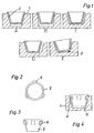
- FIGS. 1A to 1E A precise arrangement of the interchangeable liners with the respective vapor deposition material According to the current state of the art, however, the crucible is not possible, as shown in FIGS. 1A to 1E.
- the identifiable undefined Layers between the relatively cold copper crucible 1 and the replaceable relatively hot liners 2 with the respective vapor deposition material produce a strong one fluctuating and uncontrollable temperature distribution on the liner.
- the liner has spacers centrically as well as circumferentially and if necessary also at the bottom on the wall of the crucible spaced a predetermined distance in the crucible is supported.
- the Distance means from the outer wall of the liner or from the inner wall of the crucible projecting cams or ribs distributed around the circumference are or are formed by a comprehensive survey, further that the distance means engage positively in counter grooves.
- an interchangeable arrangement is the interchangeable Liner 2 with the respective vapor deposition material in the crucible 1 with the known ones Arrangements according to FIGS. 1A to 1E are not possible.
- Such crucibles and thus also the associated liners can be of any type Configuration.
- such crucibles and, accordingly, the liners cylindrical with tapered wall.
- FIGS. 2 to 4 there is now a positionally accurate arrangement according to the invention the interchangeable liner with the respective vapor deposition material in the crucible that the liner 2 is spaced 4 centrally and circumferentially and if necessary also spaced at the bottom with a predetermined distance 5 in the crucible 1 is supported.
- the spacing means 4 from the outer wall of the liner 2 or cams protruding from the inner wall of the crucible and distributed around the circumference be ribs or are formed by a comprehensive projection.
- spacing means 4 can engage in a form-fitting manner in opposing grooves (Not shown).
- the arrangement is clear and repeatable of the liner in the crucible achieved what a regular evaporation and regular heat radiation and thus a high-quality vapor deposition layer guaranteed on the substrate to be vaporized.
- the defined distance between the liner and the crucible leaves an unobstructed and thus pressure-free outgassing of any overflow material. Be further thermo-mechanical stresses so far excluded that the Liner life of such liners can be increased several times.
Landscapes
- Chemical & Material Sciences (AREA)
- Chemical Kinetics & Catalysis (AREA)
- Engineering & Computer Science (AREA)
- Materials Engineering (AREA)
- Mechanical Engineering (AREA)
- Metallurgy (AREA)
- Organic Chemistry (AREA)
- Health & Medical Sciences (AREA)
- Toxicology (AREA)
- Physical Vapour Deposition (AREA)
- Application Of Or Painting With Fluid Materials (AREA)
Abstract
Description
- Fig. 1A bis 1E
- einen Liner in einem Tiegel des Standes der Technik, im Schnitt, mit verschiedenen undefinierten Lagen zwischen Tiegel und dem auswechselbaren Liner; und
- Fig. 2 bis 4
- in Drauf- und Seitenansicht einen Liner resp. im Schnitt einen Liner in einem Tiegel gemäss der vorliegenden Erfindung.
Claims (3)
- Elektronenstrahlverdampfer für Vacuum-Beschichtungsanlagen, mit mindestens einem Tiegel zur Aufnahme eines Liners (Napf) mit einem aufzudampfenden Material
dadurch gekennzeichnet,
dass der Liner (2) über Abstandsmittel (4) zentrisch sowie umfänglich und gegebenenfalls auch bodenseitig mit vorgegebenem Abstand (5) distanziert im Tiegel (1) abgestützt ist. - Elektronenstrahlverdampfer nach Anspruch 1, dadurch gekennzeichnet, dass die Abstandsmittel (4) von der Aussenwandung des Liners (2) oder von der Innenwandung des Tiegels (1) abragende, am Umfang verteilte Nocken oder Rippen sind oder durch eine umgreifende Abragung gebildet sind.
- Elektronenstrahlverdampfer nach Anspruch 2, dadurch gekennzeichnet, dass die Abstandsmittel (4) in Gegennuten formschlüssig eingreifen.
Applications Claiming Priority (2)
| Application Number | Priority Date | Filing Date | Title |
|---|---|---|---|
| CH00819/99A CH693746A5 (de) | 1999-05-04 | 1999-05-04 | Elektronenstrahlverdampfer fuer Vacuum-Beschichtungsanlagen. |
| CH81999 | 1999-05-04 |
Publications (2)
| Publication Number | Publication Date |
|---|---|
| EP1050596A1 true EP1050596A1 (de) | 2000-11-08 |
| EP1050596B1 EP1050596B1 (de) | 2005-09-07 |
Family
ID=4195936
Family Applications (1)
| Application Number | Title | Priority Date | Filing Date |
|---|---|---|---|
| EP00107652A Expired - Lifetime EP1050596B1 (de) | 1999-05-04 | 2000-04-10 | Elektronenstrahlverdampfer für Vacuum-Beschichtungsanlagen |
Country Status (5)
| Country | Link |
|---|---|
| US (1) | US6384367B1 (de) |
| EP (1) | EP1050596B1 (de) |
| AT (1) | ATE304065T1 (de) |
| CH (1) | CH693746A5 (de) |
| DE (1) | DE50011094D1 (de) |
Cited By (1)
| Publication number | Priority date | Publication date | Assignee | Title |
|---|---|---|---|---|
| CN103080366A (zh) * | 2011-06-29 | 2013-05-01 | 松下电器产业株式会社 | 加热装置、真空加热方法和薄膜制造方法 |
Families Citing this family (2)
| Publication number | Priority date | Publication date | Assignee | Title |
|---|---|---|---|---|
| AT12783U1 (de) * | 2011-08-05 | 2012-11-15 | Plansee Se | Tiegel zur kristallzucht |
| US20220228250A1 (en) * | 2021-01-15 | 2022-07-21 | Phoenix Silicon International Corp. | Crucible and vapor deposition apparatus |
Citations (3)
| Publication number | Priority date | Publication date | Assignee | Title |
|---|---|---|---|---|
| US4700660A (en) * | 1984-06-12 | 1987-10-20 | Kievsky Politekhnichesky Institut | Evaporator for depositing films in a vacuum |
| JPS6393855A (ja) * | 1986-10-07 | 1988-04-25 | Mitsubishi Electric Corp | 蒸着装置 |
| JPH0293063A (ja) * | 1988-09-30 | 1990-04-03 | Mitsubishi Heavy Ind Ltd | 真空蒸発装置用るつぼ |
Family Cites Families (2)
| Publication number | Priority date | Publication date | Assignee | Title |
|---|---|---|---|---|
| US4866239A (en) * | 1988-05-31 | 1989-09-12 | The Boc Group, Inc. | Vapor source assembly with crucible |
| US5111022A (en) * | 1989-08-23 | 1992-05-05 | Tfi Telemark | Cooling system for electron beam gun and method |
-
1999
- 1999-05-04 CH CH00819/99A patent/CH693746A5/de not_active IP Right Cessation
-
2000
- 2000-04-10 AT AT00107652T patent/ATE304065T1/de not_active IP Right Cessation
- 2000-04-10 EP EP00107652A patent/EP1050596B1/de not_active Expired - Lifetime
- 2000-04-10 DE DE50011094T patent/DE50011094D1/de not_active Expired - Lifetime
- 2000-05-04 US US09/564,978 patent/US6384367B1/en not_active Expired - Lifetime
Patent Citations (3)
| Publication number | Priority date | Publication date | Assignee | Title |
|---|---|---|---|---|
| US4700660A (en) * | 1984-06-12 | 1987-10-20 | Kievsky Politekhnichesky Institut | Evaporator for depositing films in a vacuum |
| JPS6393855A (ja) * | 1986-10-07 | 1988-04-25 | Mitsubishi Electric Corp | 蒸着装置 |
| JPH0293063A (ja) * | 1988-09-30 | 1990-04-03 | Mitsubishi Heavy Ind Ltd | 真空蒸発装置用るつぼ |
Non-Patent Citations (2)
| Title |
|---|
| PATENT ABSTRACTS OF JAPAN vol. 012, no. 333 (C - 526) 8 September 1988 (1988-09-08) * |
| PATENT ABSTRACTS OF JAPAN vol. 014, no. 294 (C - 0732) 26 June 1990 (1990-06-26) * |
Cited By (2)
| Publication number | Priority date | Publication date | Assignee | Title |
|---|---|---|---|---|
| CN103080366A (zh) * | 2011-06-29 | 2013-05-01 | 松下电器产业株式会社 | 加热装置、真空加热方法和薄膜制造方法 |
| CN103080366B (zh) * | 2011-06-29 | 2014-12-24 | 松下电器产业株式会社 | 加热装置、真空加热方法和薄膜制造方法 |
Also Published As
| Publication number | Publication date |
|---|---|
| EP1050596B1 (de) | 2005-09-07 |
| CH693746A5 (de) | 2004-01-15 |
| DE50011094D1 (de) | 2005-10-13 |
| US6384367B1 (en) | 2002-05-07 |
| ATE304065T1 (de) | 2005-09-15 |
Similar Documents
| Publication | Publication Date | Title |
|---|---|---|
| EP0306612B1 (de) | Verfahren zur Aufbringung von Schichten auf Substraten | |
| DE69006672T2 (de) | Verfahren und Vorrichtung zur Dampfphasenauftragung eines Werkstoffs auf ein Substrat. | |
| EP0962673B1 (de) | Gleitlagerschale und Verfahren zu ihrer Herstellung | |
| DE3401815C2 (de) | Vorrichtung zum drehbaren Halten von durch physikalische Dampfabscheidung in einer evakuierten Kammer zu beschichtenden Substraten | |
| EP2271787B1 (de) | Verdampferkörper | |
| DE60317600T2 (de) | Therophysikalisches dampfablagerungsgerät mit entfernbarer/entfernbaren dampfquelle(n) | |
| EP1041169B1 (de) | Vorrichtung und Verfahren zur Beschichtung von Substraten durch Aufdampfen mittels eines PVD-Verfahrens | |
| DE3590269T (de) | Verfahren zum Aufbringen von dünnen Schichten durch Vakuumaufdampfen | |
| EP0887438A1 (de) | Verfahren zur Oberflächenvergütung innerer Oberflächen von Hohlkörpern und Vorrichtung zur Durchführung des Verfahrens | |
| DE102009040086A1 (de) | Verfahren und Vorrichtung zur Beschichtung von Substraten aus der Dampfphase | |
| DE9102052U1 (de) | Indirekt gekühlter Verdampfer mit Schnellwechselsystem | |
| DE2917841A1 (de) | Verdampfer fuer vakuumaufdampfanlagen | |
| DE202019006017U1 (de) | Vorrichtung zur Herstellung der dreidimensionalen Objekte | |
| EP1050596B1 (de) | Elektronenstrahlverdampfer für Vacuum-Beschichtungsanlagen | |
| DE3404944A1 (de) | Zusammengesetzter koerper | |
| WO2013097842A2 (de) | Vorrichtung zum verdampfen eines verdampfungsguts | |
| EP0490068B1 (de) | Verfahren zum Zentrieren eines Elektronenstrahles | |
| EP0282540B1 (de) | Verfahren und vorrichtung zum metallisieren von folienoberflächen | |
| EP0393600A2 (de) | Vorrichtung mit einem Tiegel in einer Effusionszelle einer Molekularstrahlepitaxieanlage | |
| WO2000016373A1 (de) | Targetanordnung für eine arc-verdampfungs-kammer | |
| DE4006457C2 (de) | Verfahren zum Verdampfen von Material in einer Vakuumaufdampfanlage sowie Anlage derselben | |
| DE102010036332B4 (de) | Verfahren zum Beschichten von Elektroden für die Elektrolyse mittels eines Lichtbogens | |
| DE2841969C2 (de) | Verdampfertiegel für das Verdampfen von Legierungen mit Komponenten mit unterschiedlichen Dampfdrücken | |
| DE102012022744B4 (de) | Vorrichtung zum Einstellen einer Gasphase in einer Reaktionskammer | |
| DE4421045C2 (de) | Einrichtung zur plamagestützten Beschichtung von Substraten, insbesondere mit elektrisch isolierendem Material |
Legal Events
| Date | Code | Title | Description |
|---|---|---|---|
| PUAI | Public reference made under article 153(3) epc to a published international application that has entered the european phase |
Free format text: ORIGINAL CODE: 0009012 |
|
| AK | Designated contracting states |
Kind code of ref document: A1 Designated state(s): AT BE CH CY DE DK ES FI FR GB GR IE IT LI LU MC NL PT SE |
|
| AX | Request for extension of the european patent |
Free format text: AL;LT;LV;MK;RO;SI |
|
| 17P | Request for examination filed |
Effective date: 20010508 |
|
| AKX | Designation fees paid |
Free format text: AT BE CH CY DE DK ES FI FR GB GR IE IT LI LU MC NL PT SE |
|
| 17Q | First examination report despatched |
Effective date: 20040914 |
|
| GRAP | Despatch of communication of intention to grant a patent |
Free format text: ORIGINAL CODE: EPIDOSNIGR1 |
|
| GRAS | Grant fee paid |
Free format text: ORIGINAL CODE: EPIDOSNIGR3 |
|
| GRAA | (expected) grant |
Free format text: ORIGINAL CODE: 0009210 |
|
| AK | Designated contracting states |
Kind code of ref document: B1 Designated state(s): AT BE CH CY DE DK ES FI FR GB GR IE IT LI LU MC NL PT SE |
|
| PG25 | Lapsed in a contracting state [announced via postgrant information from national office to epo] |
Ref country code: IE Free format text: LAPSE BECAUSE OF FAILURE TO SUBMIT A TRANSLATION OF THE DESCRIPTION OR TO PAY THE FEE WITHIN THE PRESCRIBED TIME-LIMIT Effective date: 20050907 Ref country code: FI Free format text: LAPSE BECAUSE OF FAILURE TO SUBMIT A TRANSLATION OF THE DESCRIPTION OR TO PAY THE FEE WITHIN THE PRESCRIBED TIME-LIMIT Effective date: 20050907 Ref country code: NL Free format text: LAPSE BECAUSE OF FAILURE TO SUBMIT A TRANSLATION OF THE DESCRIPTION OR TO PAY THE FEE WITHIN THE PRESCRIBED TIME-LIMIT Effective date: 20050907 |
|
| REG | Reference to a national code |
Ref country code: GB Ref legal event code: FG4D Free format text: NOT ENGLISH |
|
| REG | Reference to a national code |
Ref country code: CH Ref legal event code: EP |
|
| REG | Reference to a national code |
Ref country code: IE Ref legal event code: FG4D Free format text: LANGUAGE OF EP DOCUMENT: GERMAN |
|
| REF | Corresponds to: |
Ref document number: 50011094 Country of ref document: DE Date of ref document: 20051013 Kind code of ref document: P |
|
| GBT | Gb: translation of ep patent filed (gb section 77(6)(a)/1977) |
Effective date: 20051012 |
|
| PG25 | Lapsed in a contracting state [announced via postgrant information from national office to epo] |
Ref country code: GR Free format text: LAPSE BECAUSE OF FAILURE TO SUBMIT A TRANSLATION OF THE DESCRIPTION OR TO PAY THE FEE WITHIN THE PRESCRIBED TIME-LIMIT Effective date: 20051207 Ref country code: SE Free format text: LAPSE BECAUSE OF FAILURE TO SUBMIT A TRANSLATION OF THE DESCRIPTION OR TO PAY THE FEE WITHIN THE PRESCRIBED TIME-LIMIT Effective date: 20051207 Ref country code: DK Free format text: LAPSE BECAUSE OF FAILURE TO SUBMIT A TRANSLATION OF THE DESCRIPTION OR TO PAY THE FEE WITHIN THE PRESCRIBED TIME-LIMIT Effective date: 20051207 |
|
| PG25 | Lapsed in a contracting state [announced via postgrant information from national office to epo] |
Ref country code: PT Free format text: LAPSE BECAUSE OF FAILURE TO SUBMIT A TRANSLATION OF THE DESCRIPTION OR TO PAY THE FEE WITHIN THE PRESCRIBED TIME-LIMIT Effective date: 20060207 |
|
| NLV1 | Nl: lapsed or annulled due to failure to fulfill the requirements of art. 29p and 29m of the patents act | ||
| PG25 | Lapsed in a contracting state [announced via postgrant information from national office to epo] |
Ref country code: AT Free format text: LAPSE BECAUSE OF NON-PAYMENT OF DUE FEES Effective date: 20060410 |
|
| PG25 | Lapsed in a contracting state [announced via postgrant information from national office to epo] |
Ref country code: LI Free format text: LAPSE BECAUSE OF NON-PAYMENT OF DUE FEES Effective date: 20060430 Ref country code: BE Free format text: LAPSE BECAUSE OF NON-PAYMENT OF DUE FEES Effective date: 20060430 Ref country code: CH Free format text: LAPSE BECAUSE OF NON-PAYMENT OF DUE FEES Effective date: 20060430 Ref country code: MC Free format text: LAPSE BECAUSE OF NON-PAYMENT OF DUE FEES Effective date: 20060430 |
|
| REG | Reference to a national code |
Ref country code: IE Ref legal event code: FD4D |
|
| ET | Fr: translation filed | ||
| PLBE | No opposition filed within time limit |
Free format text: ORIGINAL CODE: 0009261 |
|
| STAA | Information on the status of an ep patent application or granted ep patent |
Free format text: STATUS: NO OPPOSITION FILED WITHIN TIME LIMIT |
|
| 26N | No opposition filed |
Effective date: 20060608 |
|
| REG | Reference to a national code |
Ref country code: CH Ref legal event code: PL |
|
| BERE | Be: lapsed |
Owner name: SATIS VACUUM INDUSTRIES VERTRIEBS - A.G. Effective date: 20060430 |
|
| PG25 | Lapsed in a contracting state [announced via postgrant information from national office to epo] |
Ref country code: LU Free format text: LAPSE BECAUSE OF NON-PAYMENT OF DUE FEES Effective date: 20060410 |
|
| PG25 | Lapsed in a contracting state [announced via postgrant information from national office to epo] |
Ref country code: CY Free format text: LAPSE BECAUSE OF FAILURE TO SUBMIT A TRANSLATION OF THE DESCRIPTION OR TO PAY THE FEE WITHIN THE PRESCRIBED TIME-LIMIT Effective date: 20050907 |
|
| REG | Reference to a national code |
Ref country code: FR Ref legal event code: CD Ref country code: FR Ref legal event code: CA |
|
| PG25 | Lapsed in a contracting state [announced via postgrant information from national office to epo] |
Ref country code: ES Free format text: LAPSE BECAUSE OF NON-PAYMENT OF DUE FEES Effective date: 20060430 |
|
| PGFP | Annual fee paid to national office [announced via postgrant information from national office to epo] |
Ref country code: GB Payment date: 20140530 Year of fee payment: 15 |
|
| PGFP | Annual fee paid to national office [announced via postgrant information from national office to epo] |
Ref country code: FR Payment date: 20140411 Year of fee payment: 15 Ref country code: IT Payment date: 20140424 Year of fee payment: 15 Ref country code: DE Payment date: 20140422 Year of fee payment: 15 |
|
| REG | Reference to a national code |
Ref country code: DE Ref legal event code: R119 Ref document number: 50011094 Country of ref document: DE |
|
| GBPC | Gb: european patent ceased through non-payment of renewal fee |
Effective date: 20150410 |
|
| PG25 | Lapsed in a contracting state [announced via postgrant information from national office to epo] |
Ref country code: DE Free format text: LAPSE BECAUSE OF NON-PAYMENT OF DUE FEES Effective date: 20151103 Ref country code: IT Free format text: LAPSE BECAUSE OF NON-PAYMENT OF DUE FEES Effective date: 20150410 Ref country code: GB Free format text: LAPSE BECAUSE OF NON-PAYMENT OF DUE FEES Effective date: 20150410 |
|
| REG | Reference to a national code |
Ref country code: FR Ref legal event code: ST Effective date: 20151231 |
|
| PG25 | Lapsed in a contracting state [announced via postgrant information from national office to epo] |
Ref country code: FR Free format text: LAPSE BECAUSE OF NON-PAYMENT OF DUE FEES Effective date: 20150430 |