EP1050347A2 - Ultraschallwandler - Google Patents
Ultraschallwandler Download PDFInfo
- Publication number
- EP1050347A2 EP1050347A2 EP99810540A EP99810540A EP1050347A2 EP 1050347 A2 EP1050347 A2 EP 1050347A2 EP 99810540 A EP99810540 A EP 99810540A EP 99810540 A EP99810540 A EP 99810540A EP 1050347 A2 EP1050347 A2 EP 1050347A2
- Authority
- EP
- European Patent Office
- Prior art keywords
- recesses
- front mass
- mass
- ultrasonic transducer
- top surface
- Prior art date
- Legal status (The legal status is an assumption and is not a legal conclusion. Google has not performed a legal analysis and makes no representation as to the accuracy of the status listed.)
- Withdrawn
Links
Images



Classifications
-
- B—PERFORMING OPERATIONS; TRANSPORTING
- B06—GENERATING OR TRANSMITTING MECHANICAL VIBRATIONS IN GENERAL
- B06B—METHODS OR APPARATUS FOR GENERATING OR TRANSMITTING MECHANICAL VIBRATIONS OF INFRASONIC, SONIC, OR ULTRASONIC FREQUENCY, e.g. FOR PERFORMING MECHANICAL WORK IN GENERAL
- B06B3/00—Methods or apparatus specially adapted for transmitting mechanical vibrations of infrasonic, sonic, or ultrasonic frequency
-
- B—PERFORMING OPERATIONS; TRANSPORTING
- B08—CLEANING
- B08B—CLEANING IN GENERAL; PREVENTION OF FOULING IN GENERAL
- B08B3/00—Cleaning by methods involving the use or presence of liquid or steam
- B08B3/04—Cleaning involving contact with liquid
- B08B3/10—Cleaning involving contact with liquid with additional treatment of the liquid or of the object being cleaned, e.g. by heat, by electricity or by vibration
- B08B3/12—Cleaning involving contact with liquid with additional treatment of the liquid or of the object being cleaned, e.g. by heat, by electricity or by vibration by sonic or ultrasonic vibrations
-
- B—PERFORMING OPERATIONS; TRANSPORTING
- B06—GENERATING OR TRANSMITTING MECHANICAL VIBRATIONS IN GENERAL
- B06B—METHODS OR APPARATUS FOR GENERATING OR TRANSMITTING MECHANICAL VIBRATIONS OF INFRASONIC, SONIC, OR ULTRASONIC FREQUENCY, e.g. FOR PERFORMING MECHANICAL WORK IN GENERAL
- B06B1/00—Methods or apparatus for generating mechanical vibrations of infrasonic, sonic, or ultrasonic frequency
- B06B1/02—Methods or apparatus for generating mechanical vibrations of infrasonic, sonic, or ultrasonic frequency making use of electrical energy
- B06B1/06—Methods or apparatus for generating mechanical vibrations of infrasonic, sonic, or ultrasonic frequency making use of electrical energy operating with piezoelectric effect or with electrostriction
- B06B1/0607—Methods or apparatus for generating mechanical vibrations of infrasonic, sonic, or ultrasonic frequency making use of electrical energy operating with piezoelectric effect or with electrostriction using multiple elements
- B06B1/0611—Methods or apparatus for generating mechanical vibrations of infrasonic, sonic, or ultrasonic frequency making use of electrical energy operating with piezoelectric effect or with electrostriction using multiple elements in a pile
- B06B1/0618—Methods or apparatus for generating mechanical vibrations of infrasonic, sonic, or ultrasonic frequency making use of electrical energy operating with piezoelectric effect or with electrostriction using multiple elements in a pile of piezo- and non-piezoelectric elements, e.g. 'Tonpilz'
Definitions
- the present invention relates to an ultrasonic transducer mounted onto the bottom or side surface of a cleaning tank of an ultrasonic cleaner.
- the present invention is an ultrasonic transducer including a front mass with slits on its top surface in order to improve the mechanical quality factor ("Qmeff") of piezoelectric ceramics, which in turn determines the cleaning efficiency of the ultrasonic cleaner.
- Qmeff mechanical quality factor
- Ultrasonic transducers use piezoelectric or magnetostrictive effect converting AC energy over 20 kHz into mechanical energy of the same frequency. Such ultrasonic transducers are especially suitable for ultrasonic cleaning, high-power plastic welding, machining and liquid atomizing.
- the conventional ultrasonic transducer for cleaning is provided with the typical cleaning tank (or container) disclosed in US Patents No. 5,641,228 and 5,722,444. If power is applied to the ultrasonic transducer, then the cleaning liquid in the cleaning tank vibrates radially and longitudinally from the center of the ultrasonic transducer mounted on the cleaning tank, thus effecting the cleaning.
- the cleaning efficiency of the ultrasonic cleaner is determined by the mechanical quality factor ("Qmeff"), dealing with the longitudinal mode vibrations of piezoelectric transducers.
- Qmeff mechanical quality factor
- the output power of the ultrasonic cleaner diminishes because the vibrations of piezoelectric ceramics are split in the longitudinal and radial mode vibrations.
- the longitudinal mode vibrations are attenuated by interference with the radial mode vibrations.
- said radial mode vibrations cause erosion of the radiating rigid plate disclosed in US Patent No. 5,722,444 and the bottom wall of the cleaning container disclosed in US Patent No. 5,641,228.
- the purpose of the present invention therefore is to present an ultrasonic transducer which improves the mechanical quality factor ("Qmeff") of piezoelectric ceramics determining the cleaning efficiency of an ultrasonic cleaner.
- the ultrasonic transducer is equipped with: an ultrasonic transducer mounted on the bottom or side surface of a cleaning tank of an ultrasonic cleaner, consisting of:
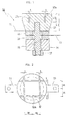
- FIG. 1 to 9 illustrate the preferred shape of the ultrasonic transducer according to the present invention.
- an adhesive mounting type ultrasonic transducer 10 includes piezoelectric ceramics 16,18; electrodes 11,13 for applying power to the piezoelectric ceramics 16,18; masses 12,14 to be vibrated by the piezoelectric ceramics 16,18; and a fastening means having a stud 15 and a nut 17.
- the piezoelectric ceramics 16,18 and the electrodes 11,13 respectively have a through hole.
- the upper electrode 11 is positioned at the top surface of the upper piezoelectric ceramic 16, and the lower electrode 13 is interposed between the upper piezoelectric ceramic 16 and the lower piezoelectric ceramic 18.
- the front mass 12 has slits 12a at the top surface in order to improve the longitudinal mechanical quality factor ("Qmeff") of the piezoelectric ceramics 16,18 determining the cleaning efficiency of the ultrasonic cleaner and having a central thread hole at the lower surface.
- Qmeff longitudinal mechanical quality factor
- the width (t) of the slits 12a is 1 ⁇ 2 mm and the depth (L2) is 1/3 ⁇ 1/2 of the longitudinal length (L1) of the front mass 12.
- a fastening means is a stud 15 with threads on both ends and a nut 17.
- the upper electrode 11, the upper piezoelectric ceramic 16, the lower electrode 13, the lower piezoelectric ceramic 18 and the lower mass 14 are assembled into a sandwich type transducer by the stud 15 and the nut 17, and connected to the front mass 12.
- the outer surface of the stud 15 should not be in contact with the inner surface of through holes of the piezoelectric ceramics 16,18, the electrodes 11,13 and the lower mass 14. Furthermore, it is preferable that the outer surface of the piezoelectric ceramics 16,18 be coated by insulating coatings.
- the upper mass 12 has a cylindrical shape and its upper section is larger than the lower section.
- the slits 12a are lattice shaped formed vertically and horizontally through the upper surface of the front, radiating mass 12. Besides, the vertical and the horizontal slits 12a are positioned at the same distance ( ⁇ ) from the center of the front mass 12. Furthermore, respective intersections of the slits 12a are positioned inside the circumference (hidden line) of the lower surface of the front mass 12.
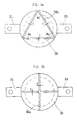
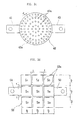
- ultrasonic transducers include front masses 22,32,42 respectively, corresponding to various shaped recesses 22a,32a,42a at its upper surface. No further detailed description about the structure of the FIG. 3a to 3f is provided because the respective structures are equal to the structure of FIG. 1 and 2. except for the shape of the recesses (slits) 22a,32a,42a.
- the recesses 32a formed at the upper surface of the front mass 32 are cross-shaped slits; an intersection of the recesses 32a is positioned at the center of the upper surface of the front mass 32.
- the recesses 42a formed at the upper surface of the front mass 42 are a large number of holes, and are formed at respective circumferences of concentric circles; the center of the concentric circles is the center of the front mass.
- the unexplained numbers 21,23,31,33,41,43 are electrodes and d is the width of the recesses (slits).
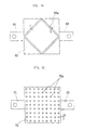
- ultrasonic transducers include front masses 52,62,72 of a regular rectangular shape.
- the recesses 52a formed at the upper surface of the front mass 52 are lattice shaped slots and are formed vertically and horizontally through the upper surface of the front mass 52.
- the recesses 62a formed at the upper surface of the front mass 62 are slots of rhomboid shape and respective apexes of recesses 62a are positioned at the edge of the upper surface of the front mass.
- the recesses 72a at the top surface of the front mass 72 are a large number of holes, formed at random on the upper surface of the front mass 72.
- the unexplained numbers 51,53,61,63,71,73 are electrodes and d is the width of the recesses.
- the bolting type ultrasonic transducer 80 includes a front mass 82 forming a thread hole 89 at its upper surface.
- a front mass 82 forming a thread hole 89 at its upper surface.
- the bolting type ultrasonic transducers include the front mass 92,102,112 forming the thread hole 99,109,119 at its upper surface.
- the thread hole 99,109,119 for fastening.
- Unexplained numbers 91,93,101,103,111,113 are electrodes and 92a, 102a, 112a are recesses.
- Examples 1 and 3 are the conventional ultrasonic transducers without recesses, and examples 2 and 4 are the present ultrasonic transducers with recesses. Moreover, Examples 1, 2 and Examples 3, 4 are assembled with the SONOX P4 and the SONOX P8, respectively.
- the efficiency of an ultrasonic transducer is determined by the mechanical quality factor ("Qmeff").
- the mechanical quality factor is 473.42 (Example 1), 578.96 (Example 2), 574.49 (Example 3) and 768.49 (Example 4). Consequently, the Examples 2 and 4 of the present invention improved by 20 ⁇ 25% of the value of the mechanical quality factor in comparison with the value of the mechanical quality factor for Examples 1 and 3.
- Example 4 in FIG. 7 shows noticeable vibration characteristics at 121.840 kHz Harmonic Resonant Frequency and at 32.402 kHz Fundamental Resonant Frequency. Therefore, an ultrasonic transducer with the front mass as in the present invention has an excellent cleaning efficiency because the Fundamental Resonant Frequency and the Harmonic Resonant Frequency coincide in cleaning.
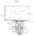
- ultrasonic transducers 10,80 in FIG. 1 and 4 are mounted onto the cleaning tank TK filled with the cleaning liquid L.
- the adhesive mounting type ultrasonic 10 is strongly attached to the bottom surface of the cleaning tank TK, because the adhesive penetrates into the recesses 12a.
- the bolting type ultrasonic 80 is fastened by the stud C fixed onto the bottom surface of the cleaning tank TK.
- the above-mentioned present invention has several advantages and characteristics, as follows.
Landscapes
- Engineering & Computer Science (AREA)
- Mechanical Engineering (AREA)
- Cleaning By Liquid Or Steam (AREA)
- Apparatuses For Generation Of Mechanical Vibrations (AREA)
Applications Claiming Priority (2)
| Application Number | Priority Date | Filing Date | Title |
|---|---|---|---|
| KR1019990015913A KR100346492B1 (ko) | 1999-05-03 | 1999-05-03 | 초음파 진동자 |
| KR9915913 | 1999-05-03 |
Publications (2)
| Publication Number | Publication Date |
|---|---|
| EP1050347A2 true EP1050347A2 (de) | 2000-11-08 |
| EP1050347A3 EP1050347A3 (de) | 2002-07-24 |
Family
ID=19583609
Family Applications (1)
| Application Number | Title | Priority Date | Filing Date |
|---|---|---|---|
| EP99810540A Withdrawn EP1050347A3 (de) | 1999-05-03 | 1999-06-18 | Ultraschallwandler |
Country Status (2)
| Country | Link |
|---|---|
| EP (1) | EP1050347A3 (de) |
| KR (1) | KR100346492B1 (de) |
Cited By (10)
| Publication number | Priority date | Publication date | Assignee | Title |
|---|---|---|---|---|
| WO2004041449A1 (en) * | 2002-11-04 | 2004-05-21 | Kimberly-Clark Worldwide, Inc. | Ultrasonic horn assembly stack component connector |
| US8574336B2 (en) | 2010-04-09 | 2013-11-05 | Southwire Company | Ultrasonic degassing of molten metals |
| US8652397B2 (en) | 2010-04-09 | 2014-02-18 | Southwire Company | Ultrasonic device with integrated gas delivery system |
| US8844897B2 (en) | 2008-03-05 | 2014-09-30 | Southwire Company, Llc | Niobium as a protective barrier in molten metals |
| CN104438029A (zh) * | 2014-12-09 | 2015-03-25 | 苏州科技学院 | 一种单激励超声椭圆振动微细加工工作平台 |
| WO2016107521A1 (zh) * | 2014-12-31 | 2016-07-07 | 简伟杰 | 一种夹心式超声波换能器前盖板组件及装有该组件的夹心式超声波换能器 |
| CN106269694A (zh) * | 2016-09-05 | 2017-01-04 | 西北农林科技大学 | 可变频便携式超声波清洗器 |
| US10233515B1 (en) | 2015-08-14 | 2019-03-19 | Southwire Company, Llc | Metal treatment station for use with ultrasonic degassing system |
| CN109622545A (zh) * | 2019-01-11 | 2019-04-16 | 夏绎 | 一种在超声波发射面与清洗物表面之间保持清洗水的结构 |
| US10316387B2 (en) | 2013-11-18 | 2019-06-11 | Southwire Company, Llc | Ultrasonic probes with gas outlets for degassing of molten metals |
Families Citing this family (6)
| Publication number | Priority date | Publication date | Assignee | Title |
|---|---|---|---|---|
| KR100604484B1 (ko) * | 2005-09-23 | 2006-07-25 | 주식회사 넵스 | 압전 세라믹을 이용한 비접촉식 초음파 구강 세정기 |
| KR100800174B1 (ko) | 2006-10-20 | 2008-02-01 | 한국기계연구원 | 메가소닉 세정모듈 |
| KR101031374B1 (ko) * | 2010-03-12 | 2011-05-06 | (주) 경일메가소닉 | 스파이크 펄스 방지용 초음파 세정 장치 |
| KR101073128B1 (ko) | 2011-04-20 | 2011-10-12 | (주) 경일메가소닉 | 초음파를 사용하는 스케일 방지와 제거를 위한 장치 및 그것이 구비된 해수전해설비 |
| KR102144403B1 (ko) * | 2019-01-28 | 2020-08-12 | 주식회사 세운이엔지 | 식기 세척기용 초음파진동자 고정 구조 |
| KR102282608B1 (ko) * | 2021-02-25 | 2021-07-29 | 주식회사 에스피티 | 압전 초음파 발생장치 |
Family Cites Families (5)
| Publication number | Priority date | Publication date | Assignee | Title |
|---|---|---|---|---|
| US3939033A (en) * | 1974-12-16 | 1976-02-17 | Branson Ultrasonics Corporation | Ultrasonic welding and cutting apparatus |
| JPH01123655A (ja) * | 1987-11-09 | 1989-05-16 | Shimada Phys & Chem Ind Co Ltd | 超音波霧化装置 |
| DE3932966C1 (de) * | 1989-10-03 | 1991-04-04 | Richard Wolf Gmbh, 7134 Knittlingen, De | |
| JPH07328503A (ja) * | 1994-06-08 | 1995-12-19 | Daishinku Co | 超音波振動子および超音波霧化装置 |
| JPH10200995A (ja) * | 1996-11-15 | 1998-07-31 | Daishinku Co | ボルト締めランジュバン型振動子 |
-
1999
- 1999-05-03 KR KR1019990015913A patent/KR100346492B1/ko not_active Expired - Fee Related
- 1999-06-18 EP EP99810540A patent/EP1050347A3/de not_active Withdrawn
Cited By (16)
| Publication number | Priority date | Publication date | Assignee | Title |
|---|---|---|---|---|
| US6841921B2 (en) | 2002-11-04 | 2005-01-11 | Kimberly-Clark Worldwide, Inc. | Ultrasonic horn assembly stack component connector |
| US7514846B2 (en) | 2002-11-04 | 2009-04-07 | Kimberly-Clark Worldwide, Inc. | Ultrasonic horn assembly stack component connector having threadless segment |
| WO2004041449A1 (en) * | 2002-11-04 | 2004-05-21 | Kimberly-Clark Worldwide, Inc. | Ultrasonic horn assembly stack component connector |
| US8844897B2 (en) | 2008-03-05 | 2014-09-30 | Southwire Company, Llc | Niobium as a protective barrier in molten metals |
| US9327347B2 (en) | 2008-03-05 | 2016-05-03 | Southwire Company, Llc | Niobium as a protective barrier in molten metals |
| US8574336B2 (en) | 2010-04-09 | 2013-11-05 | Southwire Company | Ultrasonic degassing of molten metals |
| US8652397B2 (en) | 2010-04-09 | 2014-02-18 | Southwire Company | Ultrasonic device with integrated gas delivery system |
| US10640846B2 (en) | 2010-04-09 | 2020-05-05 | Southwire Company, Llc | Ultrasonic degassing of molten metals |
| US10316387B2 (en) | 2013-11-18 | 2019-06-11 | Southwire Company, Llc | Ultrasonic probes with gas outlets for degassing of molten metals |
| CN104438029A (zh) * | 2014-12-09 | 2015-03-25 | 苏州科技学院 | 一种单激励超声椭圆振动微细加工工作平台 |
| CN104438029B (zh) * | 2014-12-09 | 2016-08-24 | 苏州科技学院 | 一种单激励超声椭圆振动微细加工工作平台 |
| WO2016107521A1 (zh) * | 2014-12-31 | 2016-07-07 | 简伟杰 | 一种夹心式超声波换能器前盖板组件及装有该组件的夹心式超声波换能器 |
| US10233515B1 (en) | 2015-08-14 | 2019-03-19 | Southwire Company, Llc | Metal treatment station for use with ultrasonic degassing system |
| CN106269694A (zh) * | 2016-09-05 | 2017-01-04 | 西北农林科技大学 | 可变频便携式超声波清洗器 |
| CN109622545A (zh) * | 2019-01-11 | 2019-04-16 | 夏绎 | 一种在超声波发射面与清洗物表面之间保持清洗水的结构 |
| CN109622545B (zh) * | 2019-01-11 | 2024-06-04 | 夏绎 | 一种在超声波发射面与清洗物表面之间保持清洗水的结构 |
Also Published As
| Publication number | Publication date |
|---|---|
| EP1050347A3 (de) | 2002-07-24 |
| KR20000072947A (ko) | 2000-12-05 |
| KR100346492B1 (ko) | 2002-07-26 |
Similar Documents
| Publication | Publication Date | Title |
|---|---|---|
| KR100346492B1 (ko) | 초음파 진동자 | |
| JP3123435B2 (ja) | 圧電型電気音響変換器 | |
| JPH01119199A (ja) | 超音波変換器 | |
| US6239535B1 (en) | Omni-directional ultrasonic transducer apparatus having controlled frequency response | |
| WO1999045600A2 (en) | Piezoelectric transformer | |
| CA2124952C (en) | Sonic or ultrasonic transducer | |
| JPH10501670A (ja) | 圧電超音波トランスデューサ | |
| CN112170149A (zh) | 一种用于金属丝拉拔的双模超声波振子 | |
| CN215918085U (zh) | 压电超声换能器 | |
| KR100413730B1 (ko) | 압전세라믹을 이용한 초음파진동자 | |
| JP3528041B2 (ja) | スピーカ | |
| JPH0141279Y2 (de) | ||
| JPH0638399U (ja) | 圧電変換器 | |
| JPS6349996Y2 (de) | ||
| JPH053270Y2 (de) | ||
| JPS59218098A (ja) | 超音波セラミツクマイクロホン | |
| JPS6113800A (ja) | 圧電ブザ− | |
| JPS5830396Y2 (ja) | 超音波セラミツクマイクロホン | |
| JPH0462516B2 (de) | ||
| JPH0462515B2 (de) | ||
| JPH0241999Y2 (de) | ||
| JPS599514Y2 (ja) | 電歪超音波振動子 | |
| JPS625400B2 (de) | ||
| JPH0536113B2 (de) | ||
| JPS6327826Y2 (de) |
Legal Events
| Date | Code | Title | Description |
|---|---|---|---|
| PUAI | Public reference made under article 153(3) epc to a published international application that has entered the european phase |
Free format text: ORIGINAL CODE: 0009012 |
|
| AK | Designated contracting states |
Kind code of ref document: A2 Designated state(s): AT BE CH CY DE DK ES FI FR GB GR IE IT LI LU MC NL PT SE |
|
| AX | Request for extension of the european patent |
Free format text: AL;LT;LV;MK;RO;SI |
|
| PUAL | Search report despatched |
Free format text: ORIGINAL CODE: 0009013 |
|
| RIC1 | Information provided on ipc code assigned before grant |
Free format text: 7B 06B 1/06 A, 7B 08B 3/12 B, 7B 06B 3/00 B |
|
| AK | Designated contracting states |
Kind code of ref document: A3 Designated state(s): AT BE CH CY DE DK ES FI FR GB GR IE IT LI LU MC NL PT SE |
|
| AX | Request for extension of the european patent |
Free format text: AL;LT;LV;MK;RO;SI |
|
| STAA | Information on the status of an ep patent application or granted ep patent |
Free format text: STATUS: THE APPLICATION IS DEEMED TO BE WITHDRAWN |
|
| 18D | Application deemed to be withdrawn |
Effective date: 20020103 |