EP1050232B1 - Lippenstiftgehäuse mit funktioneller äusserer Hülle - Google Patents
Lippenstiftgehäuse mit funktioneller äusserer Hülle Download PDFInfo
- Publication number
- EP1050232B1 EP1050232B1 EP00108919A EP00108919A EP1050232B1 EP 1050232 B1 EP1050232 B1 EP 1050232B1 EP 00108919 A EP00108919 A EP 00108919A EP 00108919 A EP00108919 A EP 00108919A EP 1050232 B1 EP1050232 B1 EP 1050232B1
- Authority
- EP
- European Patent Office
- Prior art keywords
- shell
- elevator
- accordance
- wall
- cosmetic dispenser
- Prior art date
- Legal status (The legal status is an assumption and is not a legal conclusion. Google has not performed a legal analysis and makes no representation as to the accuracy of the status listed.)
- Expired - Lifetime
Links
Images


Classifications
-
- A—HUMAN NECESSITIES
- A45—HAND OR TRAVELLING ARTICLES
- A45D—HAIRDRESSING OR SHAVING EQUIPMENT; EQUIPMENT FOR COSMETICS OR COSMETIC TREATMENTS, e.g. FOR MANICURING OR PEDICURING
- A45D40/00—Casings or accessories specially adapted for storing or handling solid or pasty toiletry or cosmetic substances, e.g. shaving soaps or lipsticks
- A45D40/02—Casings wherein movement of the lipstick or like solid is a sliding movement
- A45D40/04—Casings wherein movement of the lipstick or like solid is a sliding movement effected by a screw
Definitions
- the present invention relates to the field of lipstick and cosmetic dispensers having a propelling and retracting mechanism for a cosmetic stick contained within the dispenser, as disclosed in US 5 879 093 A.
- These slim dispenser designs typically include an elevator cup that has a threaded rod extending downwardly into and engaging a threaded base element, and which can be operated with a twisting action to extend the cosmetic stick from a nose member.
- an elevator cup that has a threaded rod extending downwardly into and engaging a threaded base element, and which can be operated with a twisting action to extend the cosmetic stick from a nose member.
- One such design is shown, for example, in my U.S. Patent No. 5,018,893.
- a disadvantage of these designs is that in order to load the dispenser with a cosmetic stick, the cosmetic stick must be formed and carefully loaded into the dispenser or cast in place in the tubular nose of the dispenser.
- the elevators of these dispensers cannot be bottom filled with a molten cosmetic product which is allowed to cool, in place, in a mold, so that the cosmetic is molded in place onto an elevator cup.
- bottom filling of an elevator cup of a cosmetic dispenser is considered a preferred method of loading the cosmetic stick into a lipstick dispenser because it simplifies the cosmetic loading operation and reduces product loss arising from breakage of the cosmetic stick on loading.
- Such bottom filling methods are used with conventional lipstick dispensers where the cup size is on the order of 12,7 mm (.50 inches) in diameter.
- bottom filling methods are not generally usable in slim dispenser designs because they will use a small diameter solid threaded rod element engaged in a cam or nut element to drive the elevator.
- the conventional dispensers use a combination of an innerbody with straight tracks working in combination with helical tracks on a cam sleeve to move an elevator cup by engagement with the elevator cup lugs.
- the "feel" of the existing slim dispenser designs is sometimes slack; desirably, a cosmetic dispenser should have a sufficient amount of swivel drag to give the dispenser a feel that is smooth and luxurious.
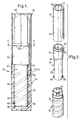
- a cosmetic dispenser in accordance with one embodiment of the invention, comprising a tubular A-shell, an elevator and a base.
- the A-shell is preferably a decorative aluminum A-shell, but has a plurality of longitudinal splines provided with the interior wall of the A-shell, either as ribs formed integrally with the wall, or as part of a plastic insert. Preferably, there are from four to eight of such splines.
- the elevator has an elevator cup at an upper end and an elevator stem extending down from the cup.
- the elevator stem is preferably hollow, and open at its lower end.
- the elevator cup is fitted inside the A-shell and has a plurality of notches around its outer wall.
- the longitudinal splines fit into the notches to keep the elevator cup in a fixed orientation relative to the A-shell.
- the elevator cup notches are formed in an annular bead extending around the outer wall of the elevator cup; for ease of manufacture, the bead is deformable, and the elevator cup notches are made by the pressure of the A-shell splines on the bead when the cosmetic dispenser is operated.
- the elevator cup notches are molded or otherwise formed in the outer wall of the elevator cup.
- the elevator stem has an exterior wall with a circular cross-section and a first feature in the form of lugs extending radially outwardly therefrom which fit into and follow a second feature in the form of an internal helically threaded track of the base.
- the base is rotatably attached to the A-shell, preferably by an annular bead extending around a perimeter of the interior wall of the A-shell in snap fitting engagement with a channel extending around a perimeter of an outer wall of the base.
- the cosmetic dispenser is operable to cause the elevator cup to travel longitudinally in the A-shell by rotation of the base element relative to the A-shell, because the rotation causes the lugs to track upwardly in the helically threaded track, with the A-shell splines received in the elevator cup notches maintaining the elevator cup in a fixed orientation relative to the A-shell.
- the elevator stem has a first feature in the form of a screw thread extending radially outwardly therefrom which interacts with a second feature in the form of mating internal screw threading in the base. Accordingly, rotation of the base causes the mating screw threads to propel the elevator upwardly or retract it downwardly.
- a desired swivel torque is provided by a plurality of separate tabs formed with and extending upwardly from the base into frictional contact with the interior wall of the A-shell to generate friction between the base and the A-shell upon relative rotation of the base and A-shell.
- the invention reduces the number of parts used in a dispenser by eliminating the innerbody found in most conventional lipstick dispensers. It provides a slender appearance and an airtight option. It provides a desirable feel due to the friction of plastic friction tabs against a metal A-shell.
- Dispenser 20 comprises an A-shell 30, an elevator 50, and a base 70.
- A-shell 30 is a decorative tubular part, preferably formed of metal, most preferably, aluminum.
- A-shell 30 has an interior wall 32 and an exterior wall 34.
- a plurality of longitudinal splines 36 are provided on the interior wall 32 of A-shell 30. Preferably, there are from four to eight such longitudinal splines 36.
- the splines 36 are integrally formed with the A-shell 30. This can be manufactured by cold forming the A-shell in an appropriate die.
- A-shell 30 may be a smooth cylinder, and the splines 36 can be incorporated in a metal or plastic insert 38 that fits inside the A-shell 30.
- Elevator 50 is preferably formed from polypropylene and has an elevator cup 52 at an upper end 54 thereof and an elevator stem 56 at a lower end 58 thereof.
- the elevator cup 52 fits inside the A-shell 30.
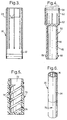
- Elevator cup 52 has a plurality of notches 60 around outer wall 62 of the cup 52. Notches 60 receive the longitudinal splines 36. The splines 36 received in the notches 60 operate to keep the cup 52 fixedly oriented relative to the A-shell 30.
- the number of notches 60 is the same as the number of splines 36.
- the notches 60 may be molded into the outer walls of the elevator cup 52.
- notches 60 are formed in an annular bead 64 extending around the outer wall 62 of the elevator cup.
- Elevator stem 56 has an exterior wall 65 with a circular cross-section and one or more lugs 66 extending radially outwardly from the wall 65.
- stem 56 is hollow, so that the dispenser 20 may be bottom filled with a cosmetic product.
- Base element 70 has an inner wall 72 with a circular cross-section and at least one, and preferably two internally helically threaded track sections 74. Helically threaded track sections 74 are engaged by the lugs 66 on elevator stem 56.
- Base 70 is rotatably attached to A-shell 30.
- Base 70 is attached to A-shell 30 by a folded over wall section 40 forming an annular bead extending around a perimeter of the interior wall 32 of the A-shell 30 in snap fitting engagement with a channel 76 extending around the perimeter of the outer wall 78 of the base 70.
- the cosmetic dispenser 20 is operable to cause the elevator cup 52 to travel longitudinally in the A-shell 30 by rotation of the base element 70 relative to the A-shell 30, because the rotation causes the lugs 66 to track upwardly in the helically threaded track sections 74. While the elevator moves upwardly, the A-shell splines 36 received in the elevator cup notches 60 maintain the elevator cup 52 in a fixed orientation relative to the A-shell 30.
- the bead 64 fits tightly against the inner wall 32 of the A-shell 30 to provide the necessary sealing fit that prevents leakage or escape of volatile components in the lipstick when the dispenser is closed with a cap and base.
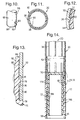
- a desirable swivel torque is provided by at least one, preferably two, or a plurality of separate tabs 80 formed with and extending upwardly from the base 70 into frictional contact with the interior wall 32 of the A-shell 30 to generate friction between the base 70 and the A-shell 30 upon relative rotation of the base 70 and A-shell 30.
- the tabs, and typically, the entire base 70 should be formed from a suitable plastic that has low creep characteristic and a good lubricity.
- the base is fabricated from Delrin®, a PTFE filled acetal manufactured by E.I. du Pont de Nemours and Company. As can be seen in FIG.
- the tabs 80 are separated from each other and have an upwardly extending segment 82 and a radially extending segment 84.
- friction tabs 80 are believed preferred, other friction elements may be used, as for example a continuous bead, which would provide a sealing fit between the components to preserve the product and prevent it from drying out.
- a continuous bead could for example connect all the segments 84 to create one annular bead, with segments 82 maintained as separate segments.
- segments 82 could be a continuous web instead of being segmented, just as segments 84 would be a continuous bead instead of being segmented.
- base element 70 has an inner wall 72 with a circular cross-section and an internally threaded track section 174. Threaded track section 174 is engaged by the exterior screw threading 166 on elevator stem 56. Accordingly, the cosmetic dispenser 20 is operable to cause the elevator cup 52 to travel longitudinally in the A-shell 30 by rotation of the base element 70 relative to the A-shell 30, because the rotation causes the external screw threading 166 to track upwardly in the threaded section 174. As before, while the elevator moves upwardly, the A-shell splines 36 received in the elevator cup notches 60 maintain the elevator cup 52 in a fixed orientation relative to the A-shell 30.
Landscapes
- Cosmetics (AREA)
- Containers And Packaging Bodies Having A Special Means To Remove Contents (AREA)
Claims (11)
- Kosmetisches Gehäuse mit
einer röhrenförmigen äußeren Hülle (30) welche eine Innenwandung (32) und eine Außenwandung (34) aufweist,
einem Förderer (50), der an seinem oberen Ende einen Förderbecher (52) und an seinem unteren Ende einen Vorschubschaft (56) aufweist, wobei der genannte Förderbecher in die genannte äußere Hülle eingepasst ist, wobei der genannte Vorschubschaft eine Außenwandung (65) mit einem kreisförmigen Querschnitt und einem ersten, auf diesem angebrachten Teil (66,166) aufweist,
einem Unterteil (70), das eine Innenwandung (72) mit einem kreisförmigen Querschnitt und ein auf diesem angebrachtes zweites Teil (74,174) aufweist, wobei das genannte erste Teil mit dem genannten zweiten Teil im Eingriff steht und wobei das genannte Unterteil drehbar mit der genannten äußeren Hülle in Verbindung steht und
Mitteln (80) zur Erzeugung eines Reibschlusses zwischen dem genannten Unterteil (70) und der genannten äußeren Hülle (30) bei Relativdrehung des Unterteils und der äußeren Hülle,
wobei das Kosmetikgehäuse dahingehend betätigbar ist, dass der genannte Förderbecher (52) durch Drehung des genannten Unterteils (70) relativ zu der genannten äußeren Hülle in Längsrichtung der äußeren Hülle bewegt werden kann,
dadurch gekennzeichnet, dass die äußere Hülle (30) eine Vielzahl von sich in Längsrichtung erstreckenden Stegen (36) aufweist, die auf der Innenwandung (32) der genannten äußeren Hülle angeordnet sind und
dass der Förderbecher (52) auf einer Außenwandung eine Vielzahl von Kerben (60) aufweist, die zur Aufnahme der genannten, sich in Längsrichtung erstreckenden Stege (36) bestimmt sind,
wobei nach Maßgabe einer Drehung des Unterteils (70) relativ zu der äußeren Hülle die genannten Stege (36) der äußeren Hülle, die in den genannten Kerben (60) des Förderbechers aufgenommen sind, den Förderbecher in einer festen Orientierung relativ zu der äußeren Hülle halten. - Kosmetikgehäuse nach Anspruch 1, dadurch gekennzeichnet, dass die Kerben (60) des genannten Förderbechers in eine Ringsicke (64) eingeformt sind, die sich entlang der Außenwandung des genannten Förderbechers erstreckt.
- Kosmetikgehäuse nach Anspruch 2, dadurch gekennzeichnet, dass die genannte Sicke verformbar ist und dass die Kerben (60) des genannten Förderbechers durch die genannten Stege (36) der äußeren Hülle geformt werden, sobald das genannte Kosmetikgehäuse betätigt wird.
- Kosmetikgehäuse nach Anspruch 1, dadurch gekennzeichnet, dass die genannten Kerben (60) des Förderbechers in die genannte Außenwandung des genannten Förderbechers eingeformt sind.
- Kosmetikgehäuse nach einem der Ansprüche 1 bis 4, dadurch gekennzeichnet, dass die genannten Stege (36) einstückig mit der genannten Innenwandung (32) der genannten äußeren Hülle geformt sind.
- Kosmetikgehäuse nach einem der vorangegangenen Ansprüche 1 bis 4, dadurch gekennzeichnet, dass innerhalb der äußeren Hülle ein Einsatz (38) eingepasst ist, wobei die genannten Stege auf dem genannten Einsatz angeordnet sind.
- Kosmetikgehäuse nach einem der vorangegangenen Ansprüche, dadurch gekennzeichnet, dass vier bis acht der genannten Stege vorgesehen sind.
- Kosmetikgehäuse nach einem der vorangegangenen Ansprüche, dadurch gekennzeichnet, dass das erste Teil auf den Vorschubschaft (56) aus einem Ansatz (66) besteht, der sich ausgehend von dem Schaft in radial auswärtiger Richtung erstreckt.
- Kosmetikgehäuse nach einem der vorangegangenen Ansprüche, dadurch gekennzeichnet, dass das zweite Teil auf der Innenwandung (72) des Unterteils (70) aus einem schraubenlinienförmigen innenseitigen Spurabschnitt (74) besteht.
- Kosmetikgehäuse nach einem der vorangegangenen Ansprüche 1 bis 7, dadurch gekennzeichnet, dass das erste Teil auf dem Vorschubschaft (56) aus einem auf diesem befindlichen Schraubgewinde (174) besteht.
- Kosmetikgehäuse nach Anspruch 10, dadurch gekennzeichnet, dass das zweite Teil auf der Innenwandung (72) des Unterteils (70) aus einem innenseitigen Gewindeabschnitt (166) besteht.
Applications Claiming Priority (4)
| Application Number | Priority Date | Filing Date | Title |
|---|---|---|---|
| US307516 | 1999-05-07 | ||
| US09/307,297 US6227733B1 (en) | 1999-05-07 | 1999-05-07 | Lipstick dispenser with functional A-shell |
| US307297 | 1999-05-07 | ||
| US09/307,516 US6231254B1 (en) | 1999-05-07 | 1999-05-07 | Slim dispenser |
Publications (3)
| Publication Number | Publication Date |
|---|---|
| EP1050232A2 EP1050232A2 (de) | 2000-11-08 |
| EP1050232A3 EP1050232A3 (de) | 2001-12-19 |
| EP1050232B1 true EP1050232B1 (de) | 2004-07-28 |
Family
ID=26975644
Family Applications (1)
| Application Number | Title | Priority Date | Filing Date |
|---|---|---|---|
| EP00108919A Expired - Lifetime EP1050232B1 (de) | 1999-05-07 | 2000-04-27 | Lippenstiftgehäuse mit funktioneller äusserer Hülle |
Country Status (3)
| Country | Link |
|---|---|
| EP (1) | EP1050232B1 (de) |
| AT (1) | ATE271801T1 (de) |
| DE (1) | DE60012402T2 (de) |
Families Citing this family (1)
| Publication number | Priority date | Publication date | Assignee | Title |
|---|---|---|---|---|
| US10455920B2 (en) | 2018-03-14 | 2019-10-29 | Margaret Spicer Meranus | Personal product applicator and dispenser |
Family Cites Families (6)
| Publication number | Priority date | Publication date | Assignee | Title |
|---|---|---|---|---|
| US4166474A (en) * | 1977-03-08 | 1979-09-04 | Eyelet Specialty Co., Inc. | Cosmetic container construction |
| DE3916670A1 (de) * | 1989-05-23 | 1990-11-29 | Schwan Stabilo Schwanhaeusser | Auftragsgeraet fuer kosmetische anwendungen |
| US5018893A (en) | 1990-03-29 | 1991-05-28 | Holloway Thomas F | Cosmetic stick dispenser |
| FR2698249B1 (fr) * | 1992-11-24 | 1998-11-20 | Suzuno Kasei Co Ltd | Mécanisme de fourniture de produits cosmétiques du type en bâton, conteneur l'employant et cartouche qui y est employée. |
| JP3333730B2 (ja) * | 1997-12-25 | 2002-10-15 | 鈴野化成株式会社 | 棒状化粧材繰出容器 |
| US6048122A (en) * | 1998-08-05 | 2000-04-11 | Suzuno Kasei Kabushiki Kaisha | Container for feeding a stick type cosmetic material |
-
2000
- 2000-04-27 EP EP00108919A patent/EP1050232B1/de not_active Expired - Lifetime
- 2000-04-27 AT AT00108919T patent/ATE271801T1/de not_active IP Right Cessation
- 2000-04-27 DE DE60012402T patent/DE60012402T2/de not_active Expired - Fee Related
Also Published As
| Publication number | Publication date |
|---|---|
| EP1050232A2 (de) | 2000-11-08 |
| DE60012402D1 (de) | 2004-09-02 |
| EP1050232A3 (de) | 2001-12-19 |
| DE60012402T2 (de) | 2005-09-01 |
| ATE271801T1 (de) | 2004-08-15 |
Similar Documents
| Publication | Publication Date | Title |
|---|---|---|
| US6231254B1 (en) | Slim dispenser | |
| US6200047B1 (en) | Sealed lipstick dispenser | |
| CA2081634C (en) | Incremental feel cosmetic dispenser | |
| US5186560A (en) | Innerbody flex tab cosmetic dispenser | |
| US5324126A (en) | Cosmetic dispenser with long lasting swivel drag effect | |
| JPS6133603A (ja) | 化粧単位 | |
| US7357588B2 (en) | Cosmetic product dispenser | |
| KR100895004B1 (ko) | 밀폐성이 향상된 화장품 케이스 | |
| JPWO2004010820A1 (ja) | スティック状化粧料用容器 | |
| US5636930A (en) | Cosmetic dispenser with cam locking feature | |
| US6227733B1 (en) | Lipstick dispenser with functional A-shell | |
| KR20200000957U (ko) | 듀얼 타입 립스틱 용기의 립스틱 홀더 승강구조 | |
| KR101782508B1 (ko) | 회전형 립스틱 용기 | |
| US6623198B2 (en) | Dispenser for cosmetics containing sunscreen | |
| EP1050232B1 (de) | Lippenstiftgehäuse mit funktioneller äusserer Hülle | |
| US20070020026A1 (en) | Airtight applicator dispenser for a product in powder form | |
| US5018893A (en) | Cosmetic stick dispenser | |
| US20060188322A1 (en) | Dispenser of a cosmetic product, typically of a lipstick | |
| US20050111901A1 (en) | Fluid cosmetic product dispenser | |
| JPH0811593B2 (ja) | アイスクリーム状製品用容器 | |
| MXPA01002426A (es) | Lapiz labial y metodo para hacer el mismo. | |
| US6071028A (en) | High product retention elevator cup | |
| KR20230147201A (ko) | 스틱 제품용 재충전가능 분배기 | |
| WO2000076367A1 (fr) | Contenant de produit de maquillage | |
| IT9021288U1 (it) | Elemento interno in un astuccio portarossetto |
Legal Events
| Date | Code | Title | Description |
|---|---|---|---|
| PUAI | Public reference made under article 153(3) epc to a published international application that has entered the european phase |
Free format text: ORIGINAL CODE: 0009012 |
|
| AK | Designated contracting states |
Kind code of ref document: A2 Designated state(s): AT BE CH CY DE DK ES FI FR GB GR IE IT LI LU MC NL PT SE |
|
| AX | Request for extension of the european patent |
Free format text: AL;LT;LV;MK;RO;SI |
|
| PUAL | Search report despatched |
Free format text: ORIGINAL CODE: 0009013 |
|
| AK | Designated contracting states |
Kind code of ref document: A3 Designated state(s): AT BE CH CY DE DK ES FI FR GB GR IE IT LI LU MC NL PT SE |
|
| AX | Request for extension of the european patent |
Free format text: AL;LT;LV;MK;RO;SI |
|
| 17P | Request for examination filed |
Effective date: 20020314 |
|
| AKX | Designation fees paid |
Free format text: AT BE CH CY DE DK ES FI FR GB GR IE IT LI LU MC NL PT SE |
|
| GRAP | Despatch of communication of intention to grant a patent |
Free format text: ORIGINAL CODE: EPIDOSNIGR1 |
|
| GRAS | Grant fee paid |
Free format text: ORIGINAL CODE: EPIDOSNIGR3 |
|
| GRAA | (expected) grant |
Free format text: ORIGINAL CODE: 0009210 |
|
| AK | Designated contracting states |
Kind code of ref document: B1 Designated state(s): AT BE CH CY DE DK ES FI FR GB GR IE IT LI LU MC NL PT SE |
|
| PG25 | Lapsed in a contracting state [announced via postgrant information from national office to epo] |
Ref country code: IT Free format text: LAPSE BECAUSE OF FAILURE TO SUBMIT A TRANSLATION OF THE DESCRIPTION OR TO PAY THE FEE WITHIN THE PRESCRIBED TIME-LIMIT;WARNING: LAPSES OF ITALIAN PATENTS WITH EFFECTIVE DATE BEFORE 2007 MAY HAVE OCCURRED AT ANY TIME BEFORE 2007. THE CORRECT EFFECTIVE DATE MAY BE DIFFERENT FROM THE ONE RECORDED. Effective date: 20040728 Ref country code: NL Free format text: LAPSE BECAUSE OF FAILURE TO SUBMIT A TRANSLATION OF THE DESCRIPTION OR TO PAY THE FEE WITHIN THE PRESCRIBED TIME-LIMIT Effective date: 20040728 Ref country code: LI Free format text: LAPSE BECAUSE OF FAILURE TO SUBMIT A TRANSLATION OF THE DESCRIPTION OR TO PAY THE FEE WITHIN THE PRESCRIBED TIME-LIMIT Effective date: 20040728 Ref country code: BE Free format text: LAPSE BECAUSE OF FAILURE TO SUBMIT A TRANSLATION OF THE DESCRIPTION OR TO PAY THE FEE WITHIN THE PRESCRIBED TIME-LIMIT Effective date: 20040728 Ref country code: CH Free format text: LAPSE BECAUSE OF FAILURE TO SUBMIT A TRANSLATION OF THE DESCRIPTION OR TO PAY THE FEE WITHIN THE PRESCRIBED TIME-LIMIT Effective date: 20040728 Ref country code: FI Free format text: LAPSE BECAUSE OF FAILURE TO SUBMIT A TRANSLATION OF THE DESCRIPTION OR TO PAY THE FEE WITHIN THE PRESCRIBED TIME-LIMIT Effective date: 20040728 Ref country code: AT Free format text: LAPSE BECAUSE OF FAILURE TO SUBMIT A TRANSLATION OF THE DESCRIPTION OR TO PAY THE FEE WITHIN THE PRESCRIBED TIME-LIMIT Effective date: 20040728 |
|
| REG | Reference to a national code |
Ref country code: GB Ref legal event code: FG4D |
|
| REG | Reference to a national code |
Ref country code: CH Ref legal event code: EP |
|
| RAP2 | Party data changed (patent owner data changed or rights of a patent transferred) |
Owner name: CROWN PACKAGING TECHNOLOGY, INC |
|
| REG | Reference to a national code |
Ref country code: IE Ref legal event code: FG4D |
|
| REF | Corresponds to: |
Ref document number: 60012402 Country of ref document: DE Date of ref document: 20040902 Kind code of ref document: P |
|
| NLT2 | Nl: modifications (of names), taken from the european patent patent bulletin |
Owner name: CROWN PACKAGING TECHNOLOGY, INC |
|
| PG25 | Lapsed in a contracting state [announced via postgrant information from national office to epo] |
Ref country code: DK Free format text: LAPSE BECAUSE OF FAILURE TO SUBMIT A TRANSLATION OF THE DESCRIPTION OR TO PAY THE FEE WITHIN THE PRESCRIBED TIME-LIMIT Effective date: 20041028 Ref country code: GR Free format text: LAPSE BECAUSE OF FAILURE TO SUBMIT A TRANSLATION OF THE DESCRIPTION OR TO PAY THE FEE WITHIN THE PRESCRIBED TIME-LIMIT Effective date: 20041028 Ref country code: SE Free format text: LAPSE BECAUSE OF FAILURE TO SUBMIT A TRANSLATION OF THE DESCRIPTION OR TO PAY THE FEE WITHIN THE PRESCRIBED TIME-LIMIT Effective date: 20041028 |
|
| PG25 | Lapsed in a contracting state [announced via postgrant information from national office to epo] |
Ref country code: ES Free format text: LAPSE BECAUSE OF FAILURE TO SUBMIT A TRANSLATION OF THE DESCRIPTION OR TO PAY THE FEE WITHIN THE PRESCRIBED TIME-LIMIT Effective date: 20041108 |
|
| NLV1 | Nl: lapsed or annulled due to failure to fulfill the requirements of art. 29p and 29m of the patents act | ||
| REG | Reference to a national code |
Ref country code: CH Ref legal event code: PL |
|
| PG25 | Lapsed in a contracting state [announced via postgrant information from national office to epo] |
Ref country code: IE Free format text: LAPSE BECAUSE OF NON-PAYMENT OF DUE FEES Effective date: 20050427 Ref country code: LU Free format text: LAPSE BECAUSE OF NON-PAYMENT OF DUE FEES Effective date: 20050427 Ref country code: CY Free format text: LAPSE BECAUSE OF FAILURE TO SUBMIT A TRANSLATION OF THE DESCRIPTION OR TO PAY THE FEE WITHIN THE PRESCRIBED TIME-LIMIT Effective date: 20050427 |
|
| PG25 | Lapsed in a contracting state [announced via postgrant information from national office to epo] |
Ref country code: MC Free format text: LAPSE BECAUSE OF NON-PAYMENT OF DUE FEES Effective date: 20050430 |
|
| ET | Fr: translation filed | ||
| PLBE | No opposition filed within time limit |
Free format text: ORIGINAL CODE: 0009261 |
|
| STAA | Information on the status of an ep patent application or granted ep patent |
Free format text: STATUS: NO OPPOSITION FILED WITHIN TIME LIMIT |
|
| 26N | No opposition filed |
Effective date: 20050429 |
|
| PG25 | Lapsed in a contracting state [announced via postgrant information from national office to epo] |
Ref country code: PT Free format text: LAPSE BECAUSE OF NON-PAYMENT OF DUE FEES Effective date: 20041228 |
|
| PGFP | Annual fee paid to national office [announced via postgrant information from national office to epo] |
Ref country code: DE Payment date: 20080430 Year of fee payment: 9 |
|
| PGFP | Annual fee paid to national office [announced via postgrant information from national office to epo] |
Ref country code: GB Payment date: 20080425 Year of fee payment: 9 |
|
| GBPC | Gb: european patent ceased through non-payment of renewal fee |
Effective date: 20090427 |
|
| REG | Reference to a national code |
Ref country code: FR Ref legal event code: ST Effective date: 20091231 |
|
| PG25 | Lapsed in a contracting state [announced via postgrant information from national office to epo] |
Ref country code: DE Free format text: LAPSE BECAUSE OF NON-PAYMENT OF DUE FEES Effective date: 20091103 |
|
| PG25 | Lapsed in a contracting state [announced via postgrant information from national office to epo] |
Ref country code: GB Free format text: LAPSE BECAUSE OF NON-PAYMENT OF DUE FEES Effective date: 20090427 Ref country code: FR Free format text: LAPSE BECAUSE OF NON-PAYMENT OF DUE FEES Effective date: 20091222 |
|
| PGFP | Annual fee paid to national office [announced via postgrant information from national office to epo] |
Ref country code: FR Payment date: 20080418 Year of fee payment: 9 |