EP1049359A2 - Mikrowellenerwärmung unter vermindertem Druck - Google Patents
Mikrowellenerwärmung unter vermindertem Druck Download PDFInfo
- Publication number
- EP1049359A2 EP1049359A2 EP00109001A EP00109001A EP1049359A2 EP 1049359 A2 EP1049359 A2 EP 1049359A2 EP 00109001 A EP00109001 A EP 00109001A EP 00109001 A EP00109001 A EP 00109001A EP 1049359 A2 EP1049359 A2 EP 1049359A2
- Authority
- EP
- European Patent Office
- Prior art keywords
- pressure
- defrosting
- frozen products
- microwave
- microwave heating
- Prior art date
- Legal status (The legal status is an assumption and is not a legal conclusion. Google has not performed a legal analysis and makes no representation as to the accuracy of the status listed.)
- Granted
Links
Images



Classifications
-
- H—ELECTRICITY
- H05—ELECTRIC TECHNIQUES NOT OTHERWISE PROVIDED FOR
- H05B—ELECTRIC HEATING; ELECTRIC LIGHT SOURCES NOT OTHERWISE PROVIDED FOR; CIRCUIT ARRANGEMENTS FOR ELECTRIC LIGHT SOURCES, IN GENERAL
- H05B6/00—Heating by electric, magnetic or electromagnetic fields
- H05B6/64—Heating using microwaves
- H05B6/6447—Method of operation or details of the microwave heating apparatus related to the use of detectors or sensors
- H05B6/6467—Method of operation or details of the microwave heating apparatus related to the use of detectors or sensors using detectors with R.F. transmitters
Definitions
- the present invention relates to defrosting technology designed to prevent dripping and the loss of quality in the defrosted products.
- the present invention relates to defrosting technology in which high-quality defrosting is performed in an extremely short amount of time by carrying out low-energy microwave heating at reduced pressure.
- the defrosting technology of the present invention can be used in various industries, including the food industry, pharmaceutical industry, cosmetic industry, cattle raising industry, marine products industry, machine manufacturing industry and home electronics manufacturing industry.
- microwave heating is carried out after the pressure has been reduced to a prescribed level (e.g., 25 torr) in order to prevent the product temperature from becoming too high during defrosting, and the progress of the defrosting process is confirmed by relaxation of the reduced pressure level.
- a prescribed level e.g. 25 torr
- the microwave radiation is emitted intermittently.
- tempering method that uses microwave radiation, in which frozen products are evenly irradiated with microwave radiation while being conveyed on a conveyor in an open atmosphere until defrosting is completed at a minus temperature near 0°C.
- frozen meat at a temperature of -40°C is defrosted by being placed into a refrigerator and left to stand for about two days.
- frozen tuna at -60°C is defrosted by being immersed in warm salt water at 40°C.
- the problem usually associated with microwave heating is knowing when to properly terminate the microwave heating.
- the first way the present invention deals with such problem is to provide an electrical discharge generating mechanism to generate microwave-induced electrical discharges during microwave heating of frozen products previously placed inside a pressure reducing chamber while the pressure is being reduced. In this way, when an electrical discharge due to microwave radiation in the reduced pressure environment is observed to take place during the defrosting process, a proper termination of microwave heating can normally be carried out.
- the time of such electrical discharge indicates the time for a proper termination of microwave heating. Accordingly, when a microwave-induced electrical discharge is detected in the reduced pressure environment, if the emission of microwave radiation is terminated immediately after the detection of such electrical discharge, it is possible to achieve defrosting without generating a drip. Further, the inside of the pressure reducing chamber is equipped with metallic elements which have single or plural number of sharp edges which include acute angled portions that normally generate precise electrical discharges.
- one cause of the generation of dripping is due to a temperature difference between the inside portion and the outside portion of the frozen products.
- the outer portion of the frozen products receive more microwave heating than the inner portion, and this results inevitably in the outer portion having a higher temperature than the inner portion.
- microwave radiation penetrates into frozen products from the outside portion thereof, the risk of the outside portion of the frozen products changing into liquid water must normally be taken into consideration. This problem can be solved by making the temperature of the inside portion of the frozen product and the temperature of the outside portion of the frozen product as close as possible.
- the present invention achieves this by generating sublimation at the outer portion of the frozen products at a minute level that reduces the temperature of the outer portion of the frozen products without affecting the product quality. By repeating this process, the temperature difference between the inner portion and the outer portion of the frozen products can be made gradually smaller.
- the precise time the pressure reducing step is terminated can be controlled by continually detecting pressure level changes at prescribed time intervals. Namely, the pressure reducing step is terminated and the pressure returning step is started when the change in the pressure level reaches a prescribed pressure level. Now, assuming the vacuum pump has no clearance error, if there is no sublimation from the frozen products, each pressure reducing step can simply be terminated at the time a prescribed pressure level is reached.
- vacuum pumps with no clearance error do not exist, and in the present invention sublimation from the frozen products is utilized to reduce the temperature difference between the inside and the outside of the frozen products in order to carry out defrosting without loss of product quality. Consequently, because there is a change in the pressure level that needs to be achieved due to the amount of sublimation being generated from the frozen products, there is no way accurate control can be carried out based on the pressure reaching the prescribed pressure level. However, by measuring the termination time of each pressure reducing step at a fixed rate in accordance with the established prescribed time or the pressure change level, it is possible to obtain a highly accurate level of control regardless of the size of the vacuum pump clearance error and the amount of sublimation.
- a vacuum pump is required to lower the pressure in the pressure reducing chamber to a pressure level at or below the sublimation pressure level that enables sublimation to be generated from the frozen products.
- Higher reduced pressure level means higher vacuum, which means chamber pressure is lower.
- Lower reduced pressure level means lower vacuum, which means chamber pressure is higher.
- the judgment of whether or not defrosting is complete can be carried out based on measured pressure changes due to sublimation from the frozen products or measured changes in the weight of the frozen products.
- dripping is most likely to occur at the parts of the frozen products that come in contact with the support jig holding the frozen products. Namely, if the support jigs are made of materials that become heated by microwave radiation, dripping will be caused by heat being transferred from the support jig to the parts of the frozen products in contact with the support jig. Accordingly, if the support jig is made of materials having a high microwave permeability or high microwave reflectivity, it becomes possible to prevent the support jig from being directly heated by the microwave radiation.
- the temperature of the support jig is close to that of the atmosphere inside the pressure reducing chamber, and this allows heat to be transferred from the support jig to the parts of the frozen products in contact with the support jig, thereby causing a temperature rise in the parts of the frozen products in contact with the support jig.
- this risk can be eliminated by making the surface area of the portions of the support jig that come into contact with the frozen products as small as possible.
- the portions of the support jig in contact with the frozen products can be reduced by using rod-shaped members, lattice-shaped members, protruding members or perforated members to support the frozen products, and in the case where the frozen products are hung from the support jig, the portions of the support jig in contact with the frozen products can be reduced by using string members, net members or hook members.
- the support jig may be fixed or rotated so long as it is possible to carry out uniform microwave heating.
- the present invention employs a microwave generator which includes a circuit for selecting a microwave output level in a stepwise or stepless manner in accordance with the weight of the frozen products.
- a pressure level adjustment valve is provided between the pressure reducing chamber and the vacuum pump, and by using this pressure level adjustment valve to let air flow in toward the vacuum pump, it is possible to adjust the pressure level without introducing air into the pressure reducing chamber. Accordingly, because defrosting is carried out under oxygen-free conditions, almost no oxidation takes place, and this makes it possible to carry out defrosting while maintaining a high degree of product quality.
- the frozen products has a much lower loss coefficient than liquid water
- the frozen products is certainly not permeable to microwave radiation, and because the microwave half-value penetration depth is quite deep for ice, once microwave radiation has been introduced, such microwave radiation is extremely efficient at heating, and this makes it possible to rapidly raise the temperature of the frozen products.
- experiments have confirmed that microwave radiation is extremely efficient at heating the frozen products so long as there are no other substances present which have a high loss coefficient, such as liquid water.
- the presence of only a very small amount of liquid water causes the microwave radiation to concentrate at the location of such liquid water, and because this takes away almost all the microwave heating of the frozen products, the defrosting process is interrupted. For this reason, it is necessary to prevent liquid water dripping from the frozen products during the defrosting process.
- a comparison experiment was carried out in which liquid water and the frozen sample were irradiated with microwave radiation. Namely, a liquid water sample constructed of a material having a prescribed amount of liquid water and a frozen sample constructed of the same material having the same amount of water in the form of ice were separately irradiated with microwave radiation to determine the relative amount of microwave radiation reflected from the liquid water and frozen sample. From the results of this experiment, it was found that the amount of microwave radiation reflected from the liquid water sample was about 30% of the amount of microwave radiation reflected from the frozen sample. Further, the results of comparing the microwave loss coefficients respectively measured for the liquid water and frozen sample showed the liquid water sample to absorb more microwave radiation than the frozen sample.
- the results of comparing temperature rises showed the opposite phenomenon to be true. Namely, at the same pressure level and microwave output level, the temperate rise for the frozen sample was higher than that for the liquid water sample. This is due to the fact that the specific heat of ice is about 50% of the specific heat of liquid water, as well as to the fact that the microwave half value penetration depth of ice (at -40°C) for microwaves having a frequency of 2,450 MHz, for example, is 780 cm, which is quite large compared with 1.3 cm for the case of liquid water.
- the high efficiency achieved when defrosting is performed by carrying out microwave heating under reduced pressure can be understood from the fact that the specific heat of the frozen products will be smaller in a reduced pressure environment than in the open atmosphere, and this makes it possible for the temperature of the frozen products to be raised at a very rapid rate using a small amount of microwave energy.
- microwave energy at about 3 kW is required to defrost about 10 kg of frozen products under an open atmosphere, while only 1 kW or less is required for defrosting the same amount of frozen products under a reduced pressure environment.
- a reduced pressure environment makes it possible to carry out defrosting in a roughly oxygen-free environment, it is possible to prevent oxidation and thereby obtain high quality defrosted products.
- the relationship discovered by the present invention is different from the relationship connected with liquid water, microwave radiation and electrical discharges known in prior art reduced pressure drying technology, in which it is known that electrical discharges will not occur when a dielectric such as liquid water is sufficiently present in a reduced pressure environment at a pressure level of 10 to 20 torr, and that electrical discharges will occur when there is relatively little liquid water present.
- the relationship discovered in the present invention shows that microwave-induced electrical discharges will not occur for some time so long as the frozen products is present at a temperature which allows penetration by microwave radiation, even when the pressure is reduced to a relatively high pressure level of about 2 torr, and that an appropriately sensitive electrical discharge will occur at the microwave output level of 1 kW due to the excess microwave radiation generated as the temperature of the frozen products rises, even when the pressure is in the range of 10 to 40 torr, and this relationship is different from the relationship connected with liquid water, microwave radiation and electrical discharges known in prior art reduced pressure drying technology. Accordingly, the principle, detection means and phenomena related to detecting electrical discharges in the defrosting technology of the present invention is completely different from that related to detecting electrical discharges in prior art reduced pressure drying technology.
- the relationship discovered in the present invention related to reduced pressure, the frozen products and microwave-induced electrical discharges makes it possible to vastly improve defrosting control, and is extremely advantageous with regards to reliability and accuracy regardless of the type, shape and temperature of the frozen products. Accordingly, the present invention makes it possible to carry out defrosting in a short amount of time while maintaining a high level of product quality.
- one or a plurality of metallic members 13 having acute angled portions is provided inside a pressure reducing chamber 1 at a location which will not cause microwave damage to the frozen products.
- a detector 8 is provided to detect such electrical discharges, and after an electrical discharge is detected, the detector sends a signal to a microwave generator 6 instructing the microwave generator 6 to terminate emission of microwave radiation.
- the detector 8 may employ an ultraviolet detection method, an electrical discharge sound detection method or any other appropriate method for detecting electrical discharges.
- the metallic members 13 that have acute angled portions may include metallic members having needle-shaped ends, metallic members having corrugated ends, or metallic members formed with ends shaped like a stirrer or the like in order to agitate the microwave radiation.
- each shape and mounting location must meet the requirement that microwave radiation is not obstructed.
- the temperature of the outside portion of the frozen products becomes higher than the temperature of the inside portion of the frozen products.
- the temperature of the inside portion can be as low as -8°C, and this is believed to be one cause of the generation of dripping.
- the vacuum pump can lower the pressure to a pressure level at or below 4.579 torr, sublimation will occur at the outside portion of the frozen products, and this sublimation will act to reduce the temperature of the outside portion of the frozen products without degrading product quality. By repeating this process, it becomes possible to shrink the temperature difference between the outside portion and the inside portion of the frozen products. Further, if this process is repeated as shown in Fig.
- the pressure can be held at or below the sublimation temperature for a prescribed period of time to make the temperature of the outside portion of the frozen products lower than the temperature of the inside portion of the frozen products.
- the inside temperature of the frozen products at -1°C
- the temperature of the outside portion can be lowered to -2°C.
- the vacuum pump in order to lower the temperature of the outside portion of the frozen products, the vacuum pump must be able to lower the pressure inside the pressure reducing chamber to a pressure level at or below the sublimation pressure for the frozen products.
- the pressure level changes in accordance with the amount of sublimation vapor produced from the frozen products makes it possible to detect the amount of sublimation vapor generated, regardless of the pressure level value.
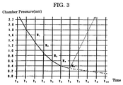
- the amount of sublimation vapor generated can be determined at a fixed rate from measurements take at prescribed time intervals for prescribed pressure level changes. For the example shown in Fig. 3, in which the prescribed time interval is 30 seconds and the prescribed pressure level change is 0.1 torr, the pressure level at the end of each prescribed time interval is compared with the pressure level measured 30 seconds prior to the current measurement, and when the change in pressure falls to 0.1 torr, the pressure reducing step is terminated.
- the prescribed time interval is set at 15 seconds, less time will be required for the change in pressure to fall to 0.1 torr compared to the case of the 30-second time interval, and this results in less sublimation vapor being produced. Accordingly, overdrying of the surface of the frozen products can be prevented by establishing appropriate values for the prescribed time interval and the prescribed pressure change.
- Fig. 4 shows an example of the pressure levels reached during each pressure level step, in which the curve "c" represents pressure levels at the beginning of the defrosting process, and the curves "b" and “a” represent pressure levels that exist as the temperature of the frozen products increases during the progression of the defrosting process. Then, if the difference in the pressure levels reached during each pressure reducing step are compared and the defrosting process is terminated at the time when a prescribed pressure level difference is reached, it becomes possible to ensure a stable defrosting termination temperature.
- Claim 6 is directed to a method of comparing the pressure levels reached at the termination of each pressure reducing step
- Claim 8 is directed to a method of comparing pressure levels reached within a prescribed time interval from a prescribed pressure level.
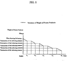
- Fig. 5 shows an example of the loss in weight of the frozen products for each pressure reducing step, and as shown in this drawing, there is a slight reduction in the weight of the frozen products each time sublimation is repeated. Further, the results of many experiments show that a successful defrosting is achieved with the method of the present invention when the weight loss after defrosting relative to the original weight of the frozen products is within 0.8%.
- this value as a reference for comparing the weight of the frozen products after each pressure reducing step with the original weight of the frozen products at the beginning of the defrosting process, it is possible to terminate the defrosting process at the time when a prescribed change in weight is reached.
- any appropriate weight measuring methods and devices may be used for measuring the weight of the frozen products, including the use of a load cell which measures the weight of the entire defrosting apparatus.
- the jig used to support the frozen products.
- the jig must not be heated by microwave radiation. This is an essential requirement, because if the jig were to be heated, a drip would inevitably occur at the points in contact with the frozen products.
- the jig should be made from a resin having a high permeability to microwave radiation such as fluororesin, polysulfone resin, polypropylene resin and "peek plastic" which was approved by the U.S. FDA for use with foodstuffs some time ago, ceramics having a high permeability to microwave radiation, or a metal having a high reflectivity such as stainless steel.
- the jig is made from a material having a high permeability to microwave radiation or a high reflectivity, because the temperature of the jig at the beginning of the defrosting process is close to that of the atmospheric temperature inside the pressure reducing chamber, the temperature of the jig starts out higher than the temperature of the frozen products. Consequently, because this results in heat being transferred from the jig to the frozen products, the greater the contact area between the jig and the frozen products, the more likely dripping will occur at such contact areas. In order to prevent such cause of dripping, in the present invention the surface area of the portions of the jig which come in contact with the frozen products is made extremely small so as prevent heat transfer. In this connection, Figs.
- 6(1)(a) ⁇ (d) show four possible examples of shaped members that can be used when the frozen products are supported on top of the jig, in which (a) shows rod-shaped members, (b) shows lattice-shaped members, (c) shows protruding members and (d) shows perforated members.
- the protruding members shown in (c) are preferred because they provide point contact at a plurality of points.
- Figs. 6(2)(e) ⁇ (g) show string members, net members and hook members used for reducing the contact area in the case where defrosting is carried out by hanging the frozen products from the support jig.
- the jig may be fixed in place or rotated so long as uniform microwave heating can be carried out.
- the pressure level and the change in the pressure level must be measured in units of 10 -1 torr or smaller, because measurements taken in units of 1 torr will not make it possible to achieve accurate control. Namely, in order to accurately determine the time defrosting should be terminated, pressure changes due to minute sublimation need to be measured in units of 10 -1 torr or smaller. This is due to the fact that it is not possible to accurately measure the generation of sublimation if measurements are made in units of roughly 1 torr, and such inaccuracy would make it difficult to prevent overdrying of the surface of the frozen products.
- direct temperature measurements of the frozen products are preferably taken using an optical fiber thermometer or the like.
- control needs to be carried out using one or more control methods like those of Claim 5 ⁇ Claim 8.
- the present invention makes it possible to prevent the frozen products from being heated with microwave radiation at too high of an output level. In this way, it becomes possible to prevent the dripping that can occur from the small protrusions normally present on the frozen products when the frozen products are heated at too high of a microwave output level.
- a variable control needs to be carried out to lower the microwave output in order to prevent the frozen products from being heated at too high of a microwave output level.
- example microwave output levels are 0.4 kW for approximately 3 kg of frozen products, 0.5 kW for approximately 5 kg of frozen products, 0.6 kW for approximately 7 kg of frozen products, 0.7 kW for approximately 9 kg of frozen products, and 1.0 kW for approximately 15 kg of frozen products.
- microwave-induced electrical discharges can be made to normally occur at such acute angled portions, and this makes it possible to carry out an extremely stable control.
- the present invention provides a defrosting method and apparatus which make it possible to carry out defrosting without a drip being generated from the frozen products.
- This control achieved with the present invention is based on the discovery that a proper termination of microwave heating can be carried out upon detection of a microwave-induced electrical discharge, whereby it becomes possible to carry out defrosting control at an accuracy level higher than anything achieved in the past.
- the present invention provides a defrosting method that makes it possible to carry out defrosting at an extremely rapid rate, and this makes the present invention useful for mass processing.
- the present invention makes it possible to obtain defrosted products having a high product quality at an extremely low defrosting cost.
- the present invention can be used to carry out defrosting in various industries.
- industries such as the meat industry and the high-quality fresh fish industry where defrosting has been difficult up to now due to problems related to product quality and transportation
- the present invention provides a defrosting method that makes it possible to obtain defrosted products having a higher product quality in a short amount of time, and because this in turn makes it possible to reduce transportation costs while achieving high product quality
- the present invention enables industry to meet the needs of the consumer.
- high quality defrosting has been difficult up to now in the meat industry, there has been a tendency to switch from frozen transport to chilled transport.
- chilled transport has a shorter freshness period, and this together with the other disadvantages of chilled transport leads to high transportation costs.
- the present invention makes it possible to achieve an extremely high quality defrosting, frozen transport can be used instead of chilled transport, and this makes it possible to reduce transportation costs.
- the present can be used to carry out industrial defrosting, and this in turn will stimulate developments in freezing technology. Further, even in the household electronics industry, the defrosting apparatus of the present invention can be made compact for high efficiency use in hotel and restaurant businesses, as well being adaptable for future high-quality household electronics.
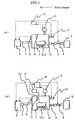
- Fig. 1(a) is a system flow sheet (in which the dashed lines indicate the flow of signals).
- control portion 10 includes the control functions of both Claim 19 and Claim 20, both Claim 19 and Claim 21, or both Claim 19 and Claim 22)
- Fig. 1(b) is a system flow sheet for the case where an optical fiber thermometer is provided (in which the dashed lines indicate the flow of signals).
- control portion 10 includes the control functions of both Claim 19 and Claim 27
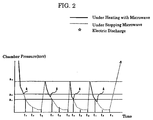
- Fig. 2 is an example of a defrosting chart (in which microwave heating is indicated by bold line portions, microwave suspension is indicated by dashed lines, and electrical discharges are indicated by " ”)
- a 1 shows the starting pressure level(e.g., 4 torr) for measuring changes in pressure according to Claim 8, and the interval from t 1 to t 2 shows the prescribed time interval for carrying out measurements.
- a 2 shows the starting pressure level (e.g., 6 torr) for continually measuring the change in pressure for each prescribed time interval according to Claim 5, and t 3 shows the time when the prescribed change in pressure is reached.
- a 3 shows the pressure level (e.g., 40 torr) that must be returned to (by means of the pressure adjustment valve) in order to restart microwave heating in accordance with Claim 5.
- the pressure level e.g., 40 torr
- Fig. 3 is a rough explanatory drawing showing the changes in pressure measured for each prescribed time interval according to Claim 5.
- N n represents the change in pressure over the prescribed time interval T n to T (n +1) .
- pressure changes are measured at the same time regardless of the actual amount of time between T n to T (n+1) .
- the prescribed time interval is set at 30 seconds and the prescribed pressure change value is set at 0.1 torr
- the pressure change N 5 reaches the prescribed value of 0.1 torr, and because this is the first time the pressure change has reached the prescribed value, the reduction of pressure is immediately terminated and a signal is sent to the pressure adjustment valve to return the pressure (as indicated by the dashed line in the drawing) to the pressure level a 3 shown in Fig. 2.
- Fig 4 is a rough explanatory drawing related to the control used in determining the termination of defrosting in accordance with Claim 6 and Claim 8.
- the curve "c" represents the pressure state at the beginning of the defrosting process
- the transition from curve “b” to curve “a” represents the pressure state as the amount of sublimation increases with increasing temperature as the defrosting process is carried out. Consequently, it becomes possible to terminate defrosting at the time when the change in pressure from an initial measured pressure level reaches a prescribed value.
- Fig. 5 is a rough explanatory drawing related to the control used in determining the termination of defrosting in accordance with Claim 7 (in which the solid lines represent changes in weight of the frozen products).
- t n indicates the termination time of each pressure reducing step. Namely, as sublimation vapor leaves the frozen products, the weight of the frozen products gradually decreases.
- the change in weight of the frozen products due to sublimation can be used to determine the time for terminating defrosting. Namely, by comparing the weight of the frozen products measured at the end of each pressure reducing step with the initial weight of the frozen products at the beginning of the defrosting process, it becomes possible to terminate the defrosting process when the change in weight reaches a prescribed value.
- Fig. 6(1) shows example jigs on which the frozen products are supported during defrosting (with the jigs being fixed or rotated).
- Fig. 6(2) shows example jigs from which frozen products are hung during defrosting (with the jigs being fixed or rotated).
- a vacuum pump2 for example, dry pump was used at an output level of 3 kW to reduce the pressure toward a target pressure level of 1.5 torr
- microwave heating was carried out at an output level of 0.6 kW
- changes in pressure were brought about using a pressure adjustment valve4 in a manner that did not introduce air into the pressure reducing chamber during the defrosting process.
- the pressure was measured in units of 0.1 torr, and the frozen beef was supported by two triangular bars made of fluororesin to create line contact or point contact, whereby the contact area between the bar and the frozen beef was made very small.
- the temperature of the frozen beef at the beginning of the defrosting process was -40°C, and the defrosting temperature was confirmed by measuring the temperature inside the frozen beef with an optical fiber thermometer inserted to a depth of 40 mm. Further, the control of the termination of defrosting was carried out in accordance with the method of Claim 6.
- FIG 1(a) and (b) 3 is exhaust valve, 5 is pressure return valve, 6 is microwave generator, 7 is waveguide, 8 is electrical discharge detection device, 9 is pressure gauge, 10 is control portion, 11a is rotatable jig for supporting frozen products, 11b is fixed jig for supporting frozen products, 12 is frozen products, 13 is metallic member which includes acute angled portion (at discharge generating position), 14 is optical fiber thermometer and 15 is temperature sensor.
- a summary of the defrosting process is shown in the table below.
- This defrosting process required 24 minutes and 30 seconds to complete. Temperature measurements taken after the defrosting process was terminated revealed an average temperature of -2.0°C for the inside portion, and an average temperature of -1.1°C for the outside portion. No dripping was generated. Further, the return pressure was 40 torr for the plurality of microwave heating steps.
- This defrosting process required 27 minutes and 50 seconds to complete. Temperature measurements taken after the defrosting process was terminated revealed an average temperature of -1.5°C for the inside portion, and an average temperature of -1.8°C for the outside portion. No dripping was generated. Further, because the weight after defrosting was measured at 7,936 grams, there was a loss of 64 grams due to sublimation. Accordingly, there was a loss rate of 0.8%, but the color was extremely well preserved. Then after left to stand for thirty minutes, the inside and outside temperatures were both about -1°C, and this defrosted tuna was confirmed to compare favorably with raw tuna.
- the temperature of the frozen pork at the beginning of the defrosting process was -40°C.
- the control of the termination of defrosting was carried out in accordance with the method of Claim 7.
- the weight of the frozen pork was measured after each pressure reducing step using a load cell, and the defrosting process was terminated at the time when the weight fell below 29,760 grams (i.e., the target value obtained by multiplying 30,000 grams by 0.992).
- a summary of the defrosting process is shown in the table below.
- This defrosting process required 34 minutes and 15 seconds to complete. Temperature measurements taken after the defrosting process was terminated revealed an average temperature of -1.9°C for the inside portion, and an average temperature of -1.5°C for the outside portion. No dripping was generated. Further, defrosting was carried out to a level that made cooking possible immediately after defrosting.
Landscapes
- Physics & Mathematics (AREA)
- Electromagnetism (AREA)
- Freezing, Cooling And Drying Of Foods (AREA)
- Electric Ovens (AREA)
- Control Of High-Frequency Heating Circuits (AREA)
- Cookers (AREA)
- Constitution Of High-Frequency Heating (AREA)
- Treatments Of Macromolecular Shaped Articles (AREA)
Applications Claiming Priority (2)
| Application Number | Priority Date | Filing Date | Title |
|---|---|---|---|
| JP11909599A JP3284409B2 (ja) | 1999-04-27 | 1999-04-27 | 解凍方法とその装置 |
| JP11909599 | 1999-04-27 |
Publications (3)
| Publication Number | Publication Date |
|---|---|
| EP1049359A2 true EP1049359A2 (de) | 2000-11-02 |
| EP1049359A3 EP1049359A3 (de) | 2005-03-30 |
| EP1049359B1 EP1049359B1 (de) | 2006-09-20 |
Family
ID=14752788
Family Applications (1)
| Application Number | Title | Priority Date | Filing Date |
|---|---|---|---|
| EP00109001A Expired - Lifetime EP1049359B1 (de) | 1999-04-27 | 2000-04-26 | Mikrowellenerwärmung unter vermindertem Druck |
Country Status (5)
| Country | Link |
|---|---|
| US (2) | US6479805B1 (de) |
| EP (1) | EP1049359B1 (de) |
| JP (1) | JP3284409B2 (de) |
| AT (1) | ATE340493T1 (de) |
| DE (1) | DE60030799T2 (de) |
Cited By (3)
| Publication number | Priority date | Publication date | Assignee | Title |
|---|---|---|---|---|
| CN100456968C (zh) * | 2001-08-28 | 2009-02-04 | 株式会社东芝 | 真空微波解冻方法及真空微波解冻机 |
| EP2106695A2 (de) | 2008-04-04 | 2009-10-07 | Ellie Corporation | Abgetautes Organ oder Gewebe oder abgetaute Zellgruppe zur Dotierung, Transplantation oder Verabreichung in einen lebenden Körper, Herstellungsverfahren dafür, unterkühlte Lösung dafür und Vorrichtung zur Herstellung des Organs oder des Gewebes |
| CN104771066A (zh) * | 2015-04-30 | 2015-07-15 | 珠海格力电器股份有限公司 | 电压力锅的排气控制方法和装置及电压力锅 |
Families Citing this family (5)
| Publication number | Priority date | Publication date | Assignee | Title |
|---|---|---|---|---|
| JP3769498B2 (ja) * | 2001-12-06 | 2006-04-26 | 東芝コンシューママーケティング株式会社 | 真空マイクロ波解凍機、及び真空マイクロ波解凍方法 |
| JP4700625B2 (ja) * | 2005-01-21 | 2011-06-15 | 俊一 八木 | 物質の減圧下における乾燥または濃縮方法 |
| JP2008079538A (ja) * | 2006-09-27 | 2008-04-10 | Prima Meat Packers Ltd | 冷凍食肉塊の解凍方法 |
| BRPI1009742B1 (pt) * | 2009-06-18 | 2018-08-14 | Weco Beratungs-Und Beteiligungs Gmbh | Processo para a secagem e tamponamento de produtos orgãnicos úmidos e equipamento para secagem e tamponamento de produtos orgânicos úmidos |
| US9380651B2 (en) * | 2010-12-23 | 2016-06-28 | Eastman Chemical Company | Microwave choke system for use in heating articles under vacuum |
Family Cites Families (8)
| Publication number | Priority date | Publication date | Assignee | Title |
|---|---|---|---|---|
| US2859534A (en) * | 1956-10-11 | 1958-11-11 | Raytheon Mfg Co | Methods and apparatus for radio frequency freeze-drying |
| JPS5436660A (en) * | 1977-08-26 | 1979-03-17 | Mayekawa Mfg Co Ltd | Defrosting process of frozen material |
| JPS58175725A (ja) * | 1982-04-07 | 1983-10-15 | Matsushita Electric Ind Co Ltd | 高周波加熱装置 |
| JP2542596B2 (ja) * | 1987-01-12 | 1996-10-09 | 株式会社東芝 | 調理器 |
| JPS63269969A (ja) * | 1987-04-27 | 1988-11-08 | House Food Ind Co Ltd | 液状物の濃縮方法 |
| DE4325581A1 (de) * | 1993-07-30 | 1995-02-02 | Dirk Wuelfing | Auftauplatte für tiefgefrorene Lebensmittel, insbesondere Fleischwaren, für Mikrowellengeräte |
| JP2932428B2 (ja) * | 1996-03-28 | 1999-08-09 | 八木 俊一 | 被乾燥物の乾燥方法とその装置 |
| JPH11290206A (ja) * | 1998-02-16 | 1999-10-26 | Fuudekkusu Japan:Kk | 冷凍食品用解凍容器 |
-
1999
- 1999-04-27 JP JP11909599A patent/JP3284409B2/ja not_active Expired - Fee Related
-
2000
- 2000-04-18 US US09/551,339 patent/US6479805B1/en not_active Expired - Fee Related
- 2000-04-26 AT AT00109001T patent/ATE340493T1/de not_active IP Right Cessation
- 2000-04-26 EP EP00109001A patent/EP1049359B1/de not_active Expired - Lifetime
- 2000-04-26 DE DE60030799T patent/DE60030799T2/de not_active Expired - Lifetime
-
2002
- 2002-04-16 US US10/123,693 patent/US6559429B2/en not_active Expired - Fee Related
Cited By (4)
| Publication number | Priority date | Publication date | Assignee | Title |
|---|---|---|---|---|
| CN100456968C (zh) * | 2001-08-28 | 2009-02-04 | 株式会社东芝 | 真空微波解冻方法及真空微波解冻机 |
| EP2106695A2 (de) | 2008-04-04 | 2009-10-07 | Ellie Corporation | Abgetautes Organ oder Gewebe oder abgetaute Zellgruppe zur Dotierung, Transplantation oder Verabreichung in einen lebenden Körper, Herstellungsverfahren dafür, unterkühlte Lösung dafür und Vorrichtung zur Herstellung des Organs oder des Gewebes |
| CN104771066A (zh) * | 2015-04-30 | 2015-07-15 | 珠海格力电器股份有限公司 | 电压力锅的排气控制方法和装置及电压力锅 |
| CN104771066B (zh) * | 2015-04-30 | 2016-12-07 | 珠海格力电器股份有限公司 | 电压力锅的排气控制方法和装置及电压力锅 |
Also Published As
| Publication number | Publication date |
|---|---|
| JP2000308478A (ja) | 2000-11-07 |
| ATE340493T1 (de) | 2006-10-15 |
| EP1049359B1 (de) | 2006-09-20 |
| EP1049359A3 (de) | 2005-03-30 |
| DE60030799D1 (de) | 2006-11-02 |
| US20020195447A1 (en) | 2002-12-26 |
| DE60030799T2 (de) | 2007-10-31 |
| JP3284409B2 (ja) | 2002-05-20 |
| US6559429B2 (en) | 2003-05-06 |
| US6479805B1 (en) | 2002-11-12 |
Similar Documents
| Publication | Publication Date | Title |
|---|---|---|
| EP2958399B1 (de) | Verarbeitung von objekten mittels hochfrequenz (hf)-energie | |
| US8492686B2 (en) | Device and method for heating using RF energy | |
| JP2744000B2 (ja) | 加熱処理の方法 | |
| US10405380B2 (en) | Device and method for heating using RF energy | |
| KR101309251B1 (ko) | 전자기 가열장치 및 이를 이용한 전자기 가열방법 | |
| US8981270B2 (en) | Method for recording temperature profiles in food packages during microwave heating using a metallic data logger | |
| EP1049359B1 (de) | Mikrowellenerwärmung unter vermindertem Druck | |
| JPH0673444B2 (ja) | 乾燥食品の製造法及び装置 | |
| JP7352782B2 (ja) | 高周波加熱装置 | |
| CN111657418A (zh) | 高频解冻装置 | |
| AU624769B2 (en) | Method and device for treating a frozen food in a microwave oven | |
| EP4014018B1 (de) | Verfahren zur analyse eines produkts zur bestimmung des gefriergrades | |
| US20240358047A1 (en) | Apparatus and method for drying plant and animal foodstuffs | |
| Ohlsson | Sterilization of food by microwaves | |
| KR20220116176A (ko) | 냉동 또는 냉동 식품을 해동하기 위한 방법, 장치 및 컴퓨터 프로그램 | |
| JP4601846B2 (ja) | 食品の熟成方法 | |
| RU2058084C1 (ru) | Электроконтактный способ приготовления пищевых продуктов | |
| JP2020184533A (ja) | マイクロ波熟成装置およびマイクロ波熟成方法 | |
| WO2023052018A1 (en) | A heating appliance and method of operating a heating appliance | |
| JPH0882423A (ja) | 加熱調理器 |
Legal Events
| Date | Code | Title | Description |
|---|---|---|---|
| PUAI | Public reference made under article 153(3) epc to a published international application that has entered the european phase |
Free format text: ORIGINAL CODE: 0009012 |
|
| AK | Designated contracting states |
Kind code of ref document: A2 Designated state(s): AT BE CH CY DE DK ES FI FR GB GR IE IT LI LU MC NL PT SE |
|
| AX | Request for extension of the european patent |
Free format text: AL;LT;LV;MK;RO;SI |
|
| PUAL | Search report despatched |
Free format text: ORIGINAL CODE: 0009013 |
|
| AK | Designated contracting states |
Kind code of ref document: A3 Designated state(s): AT BE CH CY DE DK ES FI FR GB GR IE IT LI LU MC NL PT SE |
|
| AX | Request for extension of the european patent |
Extension state: AL LT LV MK RO SI |
|
| 17P | Request for examination filed |
Effective date: 20050525 |
|
| AKX | Designation fees paid |
Designated state(s): AT BE CH CY DE DK ES FI FR GB GR IE IT LI LU MC NL PT SE |
|
| GRAP | Despatch of communication of intention to grant a patent |
Free format text: ORIGINAL CODE: EPIDOSNIGR1 |
|
| GRAS | Grant fee paid |
Free format text: ORIGINAL CODE: EPIDOSNIGR3 |
|
| GRAA | (expected) grant |
Free format text: ORIGINAL CODE: 0009210 |
|
| AK | Designated contracting states |
Kind code of ref document: B1 Designated state(s): AT BE CH CY DE DK ES FI FR GB GR IE IT LI LU MC NL PT SE |
|
| PG25 | Lapsed in a contracting state [announced via postgrant information from national office to epo] |
Ref country code: IT Free format text: LAPSE BECAUSE OF FAILURE TO SUBMIT A TRANSLATION OF THE DESCRIPTION OR TO PAY THE FEE WITHIN THE PRESCRIBED TIME-LIMIT;WARNING: LAPSES OF ITALIAN PATENTS WITH EFFECTIVE DATE BEFORE 2007 MAY HAVE OCCURRED AT ANY TIME BEFORE 2007. THE CORRECT EFFECTIVE DATE MAY BE DIFFERENT FROM THE ONE RECORDED. Effective date: 20060920 Ref country code: BE Free format text: LAPSE BECAUSE OF FAILURE TO SUBMIT A TRANSLATION OF THE DESCRIPTION OR TO PAY THE FEE WITHIN THE PRESCRIBED TIME-LIMIT Effective date: 20060920 Ref country code: AT Free format text: LAPSE BECAUSE OF FAILURE TO SUBMIT A TRANSLATION OF THE DESCRIPTION OR TO PAY THE FEE WITHIN THE PRESCRIBED TIME-LIMIT Effective date: 20060920 Ref country code: FI Free format text: LAPSE BECAUSE OF FAILURE TO SUBMIT A TRANSLATION OF THE DESCRIPTION OR TO PAY THE FEE WITHIN THE PRESCRIBED TIME-LIMIT Effective date: 20060920 Ref country code: LI Free format text: LAPSE BECAUSE OF FAILURE TO SUBMIT A TRANSLATION OF THE DESCRIPTION OR TO PAY THE FEE WITHIN THE PRESCRIBED TIME-LIMIT Effective date: 20060920 Ref country code: CH Free format text: LAPSE BECAUSE OF FAILURE TO SUBMIT A TRANSLATION OF THE DESCRIPTION OR TO PAY THE FEE WITHIN THE PRESCRIBED TIME-LIMIT Effective date: 20060920 |
|
| REG | Reference to a national code |
Ref country code: GB Ref legal event code: FG4D |
|
| REG | Reference to a national code |
Ref country code: CH Ref legal event code: EP |
|
| REG | Reference to a national code |
Ref country code: IE Ref legal event code: FG4D |
|
| REF | Corresponds to: |
Ref document number: 60030799 Country of ref document: DE Date of ref document: 20061102 Kind code of ref document: P |
|
| PG25 | Lapsed in a contracting state [announced via postgrant information from national office to epo] |
Ref country code: SE Free format text: LAPSE BECAUSE OF FAILURE TO SUBMIT A TRANSLATION OF THE DESCRIPTION OR TO PAY THE FEE WITHIN THE PRESCRIBED TIME-LIMIT Effective date: 20061220 Ref country code: DK Free format text: LAPSE BECAUSE OF FAILURE TO SUBMIT A TRANSLATION OF THE DESCRIPTION OR TO PAY THE FEE WITHIN THE PRESCRIBED TIME-LIMIT Effective date: 20061220 |
|
| PG25 | Lapsed in a contracting state [announced via postgrant information from national office to epo] |
Ref country code: ES Free format text: LAPSE BECAUSE OF FAILURE TO SUBMIT A TRANSLATION OF THE DESCRIPTION OR TO PAY THE FEE WITHIN THE PRESCRIBED TIME-LIMIT Effective date: 20061231 |
|
| PG25 | Lapsed in a contracting state [announced via postgrant information from national office to epo] |
Ref country code: PT Free format text: LAPSE BECAUSE OF FAILURE TO SUBMIT A TRANSLATION OF THE DESCRIPTION OR TO PAY THE FEE WITHIN THE PRESCRIBED TIME-LIMIT Effective date: 20070312 |
|
| ET | Fr: translation filed | ||
| REG | Reference to a national code |
Ref country code: CH Ref legal event code: PL |
|
| PGFP | Annual fee paid to national office [announced via postgrant information from national office to epo] |
Ref country code: NL Payment date: 20070426 Year of fee payment: 8 |
|
| PLBE | No opposition filed within time limit |
Free format text: ORIGINAL CODE: 0009261 |
|
| STAA | Information on the status of an ep patent application or granted ep patent |
Free format text: STATUS: NO OPPOSITION FILED WITHIN TIME LIMIT |
|
| 26N | No opposition filed |
Effective date: 20070621 |
|
| PG25 | Lapsed in a contracting state [announced via postgrant information from national office to epo] |
Ref country code: GR Free format text: LAPSE BECAUSE OF FAILURE TO SUBMIT A TRANSLATION OF THE DESCRIPTION OR TO PAY THE FEE WITHIN THE PRESCRIBED TIME-LIMIT Effective date: 20061221 |
|
| PG25 | Lapsed in a contracting state [announced via postgrant information from national office to epo] |
Ref country code: IE Free format text: LAPSE BECAUSE OF NON-PAYMENT OF DUE FEES Effective date: 20070426 |
|
| NLV4 | Nl: lapsed or anulled due to non-payment of the annual fee |
Effective date: 20081101 |
|
| PG25 | Lapsed in a contracting state [announced via postgrant information from national office to epo] |
Ref country code: NL Free format text: LAPSE BECAUSE OF NON-PAYMENT OF DUE FEES Effective date: 20081101 |
|
| PG25 | Lapsed in a contracting state [announced via postgrant information from national office to epo] |
Ref country code: MC Free format text: LAPSE BECAUSE OF NON-PAYMENT OF DUE FEES Effective date: 20070430 |
|
| PG25 | Lapsed in a contracting state [announced via postgrant information from national office to epo] |
Ref country code: LU Free format text: LAPSE BECAUSE OF NON-PAYMENT OF DUE FEES Effective date: 20070426 Ref country code: CY Free format text: LAPSE BECAUSE OF FAILURE TO SUBMIT A TRANSLATION OF THE DESCRIPTION OR TO PAY THE FEE WITHIN THE PRESCRIBED TIME-LIMIT Effective date: 20060920 |
|
| PGFP | Annual fee paid to national office [announced via postgrant information from national office to epo] |
Ref country code: DE Payment date: 20120419 Year of fee payment: 13 |
|
| PGFP | Annual fee paid to national office [announced via postgrant information from national office to epo] |
Ref country code: FR Payment date: 20120416 Year of fee payment: 13 Ref country code: GB Payment date: 20120425 Year of fee payment: 13 |
|
| GBPC | Gb: european patent ceased through non-payment of renewal fee |
Effective date: 20130426 |
|
| PG25 | Lapsed in a contracting state [announced via postgrant information from national office to epo] |
Ref country code: DE Free format text: LAPSE BECAUSE OF NON-PAYMENT OF DUE FEES Effective date: 20131101 Ref country code: GB Free format text: LAPSE BECAUSE OF NON-PAYMENT OF DUE FEES Effective date: 20130426 |
|
| REG | Reference to a national code |
Ref country code: FR Ref legal event code: ST Effective date: 20131231 |
|
| REG | Reference to a national code |
Ref country code: DE Ref legal event code: R119 Ref document number: 60030799 Country of ref document: DE Effective date: 20131101 |
|
| PG25 | Lapsed in a contracting state [announced via postgrant information from national office to epo] |
Ref country code: FR Free format text: LAPSE BECAUSE OF NON-PAYMENT OF DUE FEES Effective date: 20130430 |