EP1049333A2 - Schaltung zwischen digitalen Kameras in einem Überwachungssystem - Google Patents
Schaltung zwischen digitalen Kameras in einem Überwachungssystem Download PDFInfo
- Publication number
- EP1049333A2 EP1049333A2 EP00109020A EP00109020A EP1049333A2 EP 1049333 A2 EP1049333 A2 EP 1049333A2 EP 00109020 A EP00109020 A EP 00109020A EP 00109020 A EP00109020 A EP 00109020A EP 1049333 A2 EP1049333 A2 EP 1049333A2
- Authority
- EP
- European Patent Office
- Prior art keywords
- cameras
- frames
- image signals
- switcher
- transmission
- Prior art date
- Legal status (The legal status is an assumption and is not a legal conclusion. Google has not performed a legal analysis and makes no representation as to the accuracy of the status listed.)
- Granted
Links
Images

Classifications
-
- H—ELECTRICITY
- H04—ELECTRIC COMMUNICATION TECHNIQUE
- H04N—PICTORIAL COMMUNICATION, e.g. TELEVISION
- H04N21/00—Selective content distribution, e.g. interactive television or video on demand [VOD]
- H04N21/40—Client devices specifically adapted for the reception of or interaction with content, e.g. set-top-box [STB]; Operations thereof
- H04N21/41—Structure of client; Structure of client peripherals
- H04N21/422—Input-only peripherals, i.e. input devices connected to specially adapted client devices, e.g. global positioning system [GPS]
- H04N21/4223—Cameras
-
- H—ELECTRICITY
- H04—ELECTRIC COMMUNICATION TECHNIQUE
- H04N—PICTORIAL COMMUNICATION, e.g. TELEVISION
- H04N21/00—Selective content distribution, e.g. interactive television or video on demand [VOD]
- H04N21/20—Servers specifically adapted for the distribution of content, e.g. VOD servers; Operations thereof
- H04N21/23—Processing of content or additional data; Elementary server operations; Server middleware
- H04N21/234—Processing of video elementary streams, e.g. splicing of video streams, manipulating MPEG-4 scene graphs
- H04N21/23424—Processing of video elementary streams, e.g. splicing of video streams, manipulating MPEG-4 scene graphs involving splicing one content stream with another content stream, e.g. for inserting or substituting an advertisement
-
- H—ELECTRICITY
- H04—ELECTRIC COMMUNICATION TECHNIQUE
- H04N—PICTORIAL COMMUNICATION, e.g. TELEVISION
- H04N21/00—Selective content distribution, e.g. interactive television or video on demand [VOD]
- H04N21/40—Client devices specifically adapted for the reception of or interaction with content, e.g. set-top-box [STB]; Operations thereof
- H04N21/43—Processing of content or additional data, e.g. demultiplexing additional data from a digital video stream; Elementary client operations, e.g. monitoring of home network or synchronising decoder's clock; Client middleware
- H04N21/433—Content storage operation, e.g. storage operation in response to a pause request, caching operations
- H04N21/4334—Recording operations
-
- H—ELECTRICITY
- H04—ELECTRIC COMMUNICATION TECHNIQUE
- H04N—PICTORIAL COMMUNICATION, e.g. TELEVISION
- H04N21/00—Selective content distribution, e.g. interactive television or video on demand [VOD]
- H04N21/40—Client devices specifically adapted for the reception of or interaction with content, e.g. set-top-box [STB]; Operations thereof
- H04N21/43—Processing of content or additional data, e.g. demultiplexing additional data from a digital video stream; Elementary client operations, e.g. monitoring of home network or synchronising decoder's clock; Client middleware
- H04N21/436—Interfacing a local distribution network, e.g. communicating with another STB or one or more peripheral devices inside the home
- H04N21/43615—Interfacing a Home Network, e.g. for connecting the client to a plurality of peripherals
-
- H—ELECTRICITY
- H04—ELECTRIC COMMUNICATION TECHNIQUE
- H04N—PICTORIAL COMMUNICATION, e.g. TELEVISION
- H04N21/00—Selective content distribution, e.g. interactive television or video on demand [VOD]
- H04N21/40—Client devices specifically adapted for the reception of or interaction with content, e.g. set-top-box [STB]; Operations thereof
- H04N21/43—Processing of content or additional data, e.g. demultiplexing additional data from a digital video stream; Elementary client operations, e.g. monitoring of home network or synchronising decoder's clock; Client middleware
- H04N21/436—Interfacing a local distribution network, e.g. communicating with another STB or one or more peripheral devices inside the home
- H04N21/4363—Adapting the video or multiplex stream to a specific local network, e.g. a IEEE 1394 or Bluetooth® network
- H04N21/43632—Adapting the video or multiplex stream to a specific local network, e.g. a IEEE 1394 or Bluetooth® network involving a wired protocol, e.g. IEEE 1394
-
- H—ELECTRICITY
- H04—ELECTRIC COMMUNICATION TECHNIQUE
- H04N—PICTORIAL COMMUNICATION, e.g. TELEVISION
- H04N21/00—Selective content distribution, e.g. interactive television or video on demand [VOD]
- H04N21/40—Client devices specifically adapted for the reception of or interaction with content, e.g. set-top-box [STB]; Operations thereof
- H04N21/43—Processing of content or additional data, e.g. demultiplexing additional data from a digital video stream; Elementary client operations, e.g. monitoring of home network or synchronising decoder's clock; Client middleware
- H04N21/44—Processing of video elementary streams, e.g. splicing a video clip retrieved from local storage with an incoming video stream, rendering scenes according to MPEG-4 scene graphs
- H04N21/44016—Processing of video elementary streams, e.g. splicing a video clip retrieved from local storage with an incoming video stream, rendering scenes according to MPEG-4 scene graphs involving splicing one content stream with another content stream, e.g. for substituting a video clip
-
- H—ELECTRICITY
- H04—ELECTRIC COMMUNICATION TECHNIQUE
- H04N—PICTORIAL COMMUNICATION, e.g. TELEVISION
- H04N5/00—Details of television systems
- H04N5/222—Studio circuitry; Studio devices; Studio equipment
- H04N5/262—Studio circuits, e.g. for mixing, switching-over, change of character of image, other special effects ; Cameras specially adapted for the electronic generation of special effects
- H04N5/268—Signal distribution or switching
-
- H—ELECTRICITY
- H04—ELECTRIC COMMUNICATION TECHNIQUE
- H04N—PICTORIAL COMMUNICATION, e.g. TELEVISION
- H04N7/00—Television systems
- H04N7/18—Closed-circuit television [CCTV] systems, i.e. systems in which the video signal is not broadcast
- H04N7/181—Closed-circuit television [CCTV] systems, i.e. systems in which the video signal is not broadcast for receiving images from a plurality of remote sources
Definitions
- This present invention relates to a frame switcher and a switching, for example, the frame switcher and the switching method of recording and reproducing image signals with high efficiency while frames of images from a plurality of cameras of a monitoring system are switched, and a digital camera and the monitoring system using the frame switcher.
- a monitoring system has been widely used in which moving pictures or still pictures are picked up by digital cameras, the data from the cameras are processed and recorded by a recording/reproducing apparatus, and the data are processed, stored and reproduced by a reproducing apparatus.
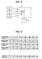
- a conventional monitoring system in which the image signals from a plurality of digital cameras are transmitted to a recording/reproducing apparatus as, for example, shown in Figs. 8 and 9.
- the monitoring system shown in Fig. 8 uses a plurality of analog cameras A, B, C, D.
- the image signals from these cameras A-D are received by a monitoring system 1, sequentially switched at certain intervals of time by a switch 2 provided within the monitoring system 1, and stored in storage unit 3.
- Fig. 9 shows outputs from the cameras A-D and an output to the storage unit 3 from the monitoring system 1.
- Each of the cameras A-D that is an analog camera always produces an image signal of frame units at certain intervals of time (for example, 1/30 second). Therefore, when the switch 2 switches the cameras A-D in turn at these time intervals, the frames are sent from all the different cameras to the storage unit as shown in Fig. 9.
- the invention proposes a digital monitoring system constructed by connecting a plurality of MPEG cameras that can be synchronized, to a switcher for switching the image signals from the cameras, and a method of switching the image signals in which the MPEG cameras can be controlled to set the transmission timings and cycle times of I frames, and the image signals of one cycle from the cameras can be buffered, and only the necessary I frames can be extracted from the buffered image signals.
- the transmission timings of I frames from the cameras are shifted in the method of switching the image signals in which the image signals of one cycle from the cameras are buffered and then only the necessary I frames are extracted.
- the I frames from the cameras are transmitted with the transmission timings of I frames being shifted, and the switcher switches the image signals from the cameras in accordance with the transmission timings of I frames.
- the transmission timings of I frames from the cameras are shifted, only the I frames from the cameras can be transmitted and received on a single channel in a time sharing manner.
- a digital camera having imaging means for picking up images, digitizing means for converting the produced image signal into a digital signal, timing control means for controlling the transmission timing of I frame of the image signal, setting means for setting the timing of the timing control means and the transmission cycle of I frame, and transmitting means for transmitting the image signal.
- I frame extracting means for extracting the necessary I frame from the image signal can be further provided to extract and transmit the I frame of the image signal with a certain timing.
- a frame switcher having receiving means for receiving image signals from a plurality of cameras that produce digital image. signals and are synchronized, buffer means for temporarily storing the image signals of one cycle received from the plurality of cameras, I frame extractor means for extracting only the I frames from the image signals stored in the buffer means, timing control means for controlling the operation timing of the I frame extractor means, setting means for setting the timing of the timing control means, and transmitting means for transmitting the image signals, whereby the I frames of image signals are extracted from the buffer means and transmitted with a certain timing.
- setting means is further provided to set the synchronization of the plurality of cameras so that the I frames are simultaneously transmitted and to set the cycle times so that they are transmitted with the same cycle time.
- another frame switcher having receiving means for receiving image signals from a plurality of cameras that produce digital image signals and are synchronized, channel switching means for switching channels on which the image signals are received, to a channel for a camera that is transmitting an I frame, timing control means for controlling the switching timing of the channel switching means, setting means for setting the timing of the timing control means, and transmitting means for transmitting the image signals, whereby the I frames of image signals are received and transmitted with a certain timing.
- buffer means are provided for storing part of I frame data of the image signals received from the plurality of cameras.
- setting means is provided to set the synchronization of the plurality of digital cameras so that the transmission timings of I frames are made different and set so that the transmission cycle times of I frames are same.
- a digital monitoring system of claim 1 is constructed by MPEG cameras that are synchronized, and a switcher.
- the cameras are set as to the transmission timings and transmission cycle times of I frames.
- the image signals of one cycle from the cameras are buffered, and only the necessary I frames are extracted from the buffered image signals. Even though the digital image signals include frames depending upon other frames, such as P frame and B frame, the frames are switched so that the desired I frames are received.
- a digital monitoring system of claim 2 is constructed by MPEG cameras that are synchronized, and a switcher.
- the cameras are set as to the transmission timings and transmission cycle times of I frames.
- the image signals of one cycle from the cameras are buffered, and only the necessary I frames are extracted from the buffered image signals.
- the transmission timings of I frames from the plurality of cameras are shifted, and the digital image signals are received by frame switching.
- a digital monitoring system of claim 3 is constructed by MPEG cameras that are synchronized, and a switcher.
- the cameras are set as to the transmission timings and transmission cycle times of I frames.
- the switcher switches the image signals from the cameras in accordance with the transmission timings of I frames.
- the transmission timings of I frames from the plurality of cameras are shifted so that the image signals are accurately and fast received with less buffer.
- a digital monitoring system of claim 4 is constructed by MPEG cameras that are synchronized, and a switcher.
- the cameras are set as to the transmission timings and transmission cycle times of I frames.
- the switcher switches the image signals from the cameras in accordance with the transmission timings of I frames.
- the transmission timings of I frames from the plurality of cameras are shifted so that only the I frames are transmitted and that a single channel is shared by the plurality of cameras in a time sharing manner. Thus, the frequency band on the network between the cameras and the switcher is effectively used.
- a method of switching image signals of claim 5 uses a plurality of cameras that produce digital image signals and are synchronized, and a switcher for switching the image signals from the plurality of cameras.
- the method has the steps of setting synchronization of a plurality of cameras so that the I frames are simultaneously transmitted, and the transmission cycle times of I frames so that the I frames are transmitted with the same cycle time, buffering the image signals of one cycle from the plurality of cameras, and extracting, by switching only the necessary I frames, from the buffered image signals.
- the digital image signals include frames depending upon other frames such as P frame and B frame, the digital image signals are received by frame switching.
- a method of switching image signals of claim 6 uses a plurality of cameras that produce digital image signals and are synchronized, and a switcher for switching the image signals from the plurality of cameras.
- the method has the steps of setting synchronization of a plurality of cameras so that I frames are simultaneously transmitted, and the transmission cycle times of I frames so that the I frames are transmitted with the same cycle time, buffering the image signals of one cycle from the plurality of cameras, and extracting, by switching the necessary I frames, from the buffered image signals while the transmission timings of I frames from the cameras are shifted.
- the digital image signals are received by frame switching.
- a method of switching image signals of claim 7 uses a plurality of cameras producing digital image signals and synchronized, and a switcher for switching the image signals from the plurality of cameras.
- the method has the steps of setting synchronization of a plurality of cameras so that the transmission timings of I frames are made different, and the transmission cycle times of I frames so that the I frames are transmitted with the same cycle time, and transmitting the I frames in such a manner that they are switched in synchronism with the above different transmission timings of I frames and that the operation timings of the cameras are shifted. Therefore, the image signals are fast and accurately received with less buffer.
- a method of switching image signals of claim 8 uses a plurality of cameras producing digital image signals and synchronized, and a switcher for switching the image signals from the plurality of cameras.
- the method has the steps of setting synchronization of a plurality of cameras so that the transmission timings of I frames are made different, and the transmission cycle times of I frames so that the I frames are transmitted with the same cycle time, and transmitting only the I frames in such a manner that the I frames are switched in synchronism with the above different transmission timings of I frames and that the operation timings of the cameras are shifted, in which a single channel is shared by the plurality of cameras in a time sharing manner.
- the frequency band on the network between the cameras and the switcher are effectively used.
- a digital camera of claim 9 has imager means for picking up images, digitizing means for converting the produced image signal into a digital signal, timing control means for controlling a transmission timing of I frame of the image signal, setting means for setting a timing of the timing control means and a transmission cycle time of I frame, and transmitting means for transmitting the image signal.
- the I frame of the image signal are transmitted with a certain timing and in a different way according to the settings in the system.
- a digital camera of claim 10 has imager means for picking up images, digitizing means for converting the produced image signal into a digital signal, I frame extracting means for extracting the necessary I frame from the image signal, timing control means for controlling a transmission timing of the I frame, setting means for setting a timing of the timing control means and a transmission cycle time of I frame, and transmitting means for transmitting the image signal.
- the setting means is provided to set a synchronization of a plurality of cameras so that I frames from the cameras are simultaneously transmitted, and a transmission cycle times so that the I frames are transmitted with the same cycle time.
- the digital image signals include frames depending upon other frame, such as P frame and B frame, the switcher receiving the image signals switches the frames to easily receive the I frames.
- the setting means is provided to set synchronization of a plurality of cameras so that transmission timings of I frames are made different, and transmission cycle times so that the I frames are transmitted with the same cycle time.
- the switcher receiving the digital image signals switches the image signals with less buffer and delay to receive the I frames.
- a frame switcher of claim 13 has receiving means for receiving the image signals from a plurality of cameras that produce digital image signals and are synchronized, buffer means for temporarily storing the image signals of one cycle received from the plurality of cameras, I frame extracting means for extracting only the necessary I frames from the buffered image signals, timing control means for controlling an operation timing of the I frame extracting means, setting means for setting a timing of the timing control means, and transmitting means for transmitting the image signals. Since the I frames of the image signals are extracted from the buffer means and transmitted with a certain timing, the digital image signals are received by frame switching even though the digital image signals include frames depending upon other frames such as P frame and B frame.
- the setting means is provided to set synchronization of a plurality of cameras so that I frames are simultaneously transmitted, and a transmission cycle times so that the I frames are transmitted with the same cycle time.
- the digital image signals include frames depending upon other frames such as P frame and B frame, the digital image signals are switched so that the I frames are easily received.
- a frame switcher of claim 15 has receiving means for receiving the image signals from a plurality of cameras that produce digital image signals and are synchronized, channel switching means for switching the channels on which the image signals are received to a channel for the camera that is transmitting the I frame, timing control means for controlling the switching timing of the channel switching means, setting means for setting a timing of the timing control means, and transmitting means for transmitting the image signals.
- the buffer means is provided to store part of I frame data of the image signals received from a plurality of cameras.
- the I frames are received orderly even though the I frames from the cameras are received and overlapped when the channel switching means is switching.
- the setting means is provided to set synchronization of a plurality of cameras so that transmission timings of I frames are made different, and transmission cycle times so that the I frames are transmitted with the same cycle time.
- the image signals are fast and accurately received with less buffer.
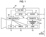
- Fig. 1 is a block diagram of a camera used in a monitoring system of the first embodiment of the invention.
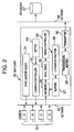
- Fig. 2 is a block diagram showing the construction of a switcher that is connected to a plurality of such cameras according to this embodiment, and that switches the I-frame outputs of image signals received from those cameras.
- a camera 10 as a digital camera that produces an MPEG output and are synchronized, a CCD image sensor 11 for picking up images to produce an image signal, a sampler 12 for sampling the image signal produced from the image sensor 11, and a coder 13 for compressing and coding the image signal.
- a buffer 14 for temporarily holding the image signal from this camera, a transmitter 16 for transmitting the image signal to a network 15, a receiver 17 for receiving data such as a command sent through the network 15, and a synchronizing timer 18 for synchronizing operations of these elements in the camera 10.
- a setter 19 for setting imaging and transmitting operations within the camera 10, and a timing controller 20 for controlling elements in the camera 10 to be timely operated to control a timing of driving the image sensor 11.
- reference numeral 25 designates a switcher
- 26 a receiver that is connected to the network 15 to receive MPEG signals from a plurality of cameras 10 (camera A, camera B, camera C and camera D)
- 27 a buffer for temporarily storing the received image signal
- 28 an I-frame extractor for extracting I frame of MPEG signal from the stored signal in the buffer
- 29 a transmission buffer for temporarily holding the I frame until the I frame data extracted by the I-frame extractor 28 is supplied from the switcher 25 to the opponent I/O
- 30 a transmitter for transmitting the I frame through a network 36
- 31 a synchronizing master clock for generating a clock signal to control synchronization of the operations of the whole system (monitoring system) including the switcher 25 and the elements or apparatus that are connected to the switcher in order to transmit and receive the image signals.
- reference numeral 32 represents a synchronizing timer for synchronizing operations of the elements in the switcher 25, 33 a setter for setting imaging and transmitting operations in the camera 10 and transmitting, receiving and data-processing operations in the switcher 25, 34 a timing controller for controlling an operation timing of each element in the switcher 25 such as driving timings of the receiver 26 and transmitter 30, and 35 a camera controller for generating control data to the cameras 10 in accordance with settings of the setter 33.
- the switcher 25 has a storage capacity enough to store one cycle of image signals from all the cameras 10 connected to the switcher 25 for a time necessary for the extraction.
- the synchronizing master clock 31, setter 33 and camera controller 35 have functions as a system controller for controlling the whole monitoring system, and the switcher 25 serves as a master apparatus for generating various kinds of commands.
- Reference numeral 36 designates a network through which the image signal produced from the transmitter 30 of the switcher 25 is transmitted to other I/O apparatus, and 37 a recorder connected to the network 36.
- the cameras 10, switcher 25 and recorder 37 are connected through the networks 15, 36, thus constituting a monitoring system.
- the networks 15, 36 are not necessary to be different, but may be the same networks.
- the operation of the monitoring system will be described below. Since a plurality of cameras 10 installed at different places are used as MPEG cameras as described above, these cameras 10 produce digital image signals.
- the digital image signal from each camera includes frame data of I frame, P frame and B frame as MPEG data. Of these frames, the I frame is to present the contents of the image by itself, but the P frame and B frame depend upon other frames and thus does not reproduce the contents of the image by itself. Therefore, in order to reproduce the frames of images from the respective cameras A-D as shown in Fig. 9, it is necessary to select the I frames from the image signals the cameras A-D of camera 10 send out.
- a plurality of cameras A-D are previously set to simultaneously send the I frames with the same cycle.
- a setting for the synchronization is performed by the instruction (generation of command) from the switcher 25.
- the setter 33 of the switcher 25 generates control data for synchronizing the cameras A-D, making the cameras A ⁇ D simultaneously send the I frames.
- the synchronization setting control data is also supplied as a command to the network 15 through the camera controller 35.
- the camera 10 receives control data through the receiver 17, and the received data is registered in the setters 19 of the respective cameras A-D.
- the setting for the transmission cycle is also performed by the instruction (generation of command) from the switcher 25.
- the setter 33 of the switcher 25 determines transmission cycle times in the cameras A-D and generates data of transmission cycle times and sends it to the cameras A-D so that each of the I frames are transmitted with a certain cycle.
- the transmission cycle data is also supplied as a command through the camera controller 35 to the network 15.
- the camera 10 receives cycle data through the receiver 17, and the cycle data is registered in the setters 19 of the respective cameras A-D. The same transmission cycle time is set in the cameras A-D.
- the timing controller 34 is set so that the frame extractor 28 is simultaneously read from the buffer 29, the I frames associated with the respective cameras A-D in one cycle.
- a control signal synchronized with the clock from the synchronizing master clock 31 of the switcher 25 controls the cameras 10 and switcher 25 to make imaging, transmitting and receiving operations. In these operations, a plurality of cameras 10 simultaneously transmit the I frames with a constant cycle according to the synchronization settings.
- the switcher 25 stores those image signals of one cycle in the buffer 27 (those signals are buffered).
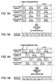
- Fig. 3A is a schematic diagram showing transmission of the image signals from the camera 10 and storing of those signals in the buffer 27.
- the I frame extractor 28 extracts only the necessary I frames from the buffered image signals.
- the I frame extractor 28 is controlled in its operation timing by the timing controller 34 in such a manner that the I frames associated with the cameras A-D are sequentially extracted from the buffered image signals according to the switching operation. In this way, the I frames from the cameras A-D are arranged in time series within one cycle.
- Fig. 3B shows the extracted I frames.
- the extracted I frames are temporarily stored in the transmission buffer 29, and then transferred to the transmitter 30.
- the transmitter 30 supplies the transferred I frames through the network 36 to the recorder 37 where they are recorded.
- the control data when the setter 33 of switcher 25 generates control data for synchronizing the cameras A-D, the control data is set so that the transmission timings of the I frames are shifted.
- the synchronization setting control data is also fed as a command through the camera controller 35 to the network 15.
- the camera 10 receives the control data through the receiver 17, and registers it in the setter 19 of each camera A-D.
- the setting of the transmission cycle is the same as in this embodiment.
- the setting of the buffer reading timing in the switcher 25 is also the same as in this embodiment.
- the I frames are respectively once transmitted from all cameras A-D in one cycle.
- the camera 10 and switcher 25 are controlled to make imaging, transmitting and receiving operations by the control signal synchronized with the clock from the synchronizing master clock 31 of the switcher 25.
- a plurality of cameras 10 transmit image signals with timings of I frames shifted and with a constant cycle according to the above synchronization setting.
- the switcher 25 stores (buffers) the image signals of one cycle in the buffer 27.
- Fig. 4A schematically shows transmission of image signals from the cameras 10 and storing of them in the buffer 27.
- the I frame extractor 28 extracts only necessary I frames from the buffered image signals.
- the I frame extractor 28 is controlled in operation timing by the timing controller 34 to sequentially extract, by switching the I frames associated with the cameras A-D from the buffered image signals in the same way as in the above case.
- the I frames associated with the cameras A-D are arranged in time series within one cycle.
- Fig. 4B shows the extracted I frames.
- the extracted I frames are temporarily stored in the transmission buffer 29, and then transmitted from the transmitter 30 through the network 36 to the recorder 37 where they are stored.
- the switcher 25 since the switcher 25 has a storage capacity enough to store, for a necessary time for extraction, the image signals of one cycle from all the cameras 10 connected to the switcher 25, the I frames fed from the plurality of cameras 10 are transmitted simultaneously or with their timings shifted.
- Fig. 5 is a block diagram of the construction of a switcher used in a monitoring system of the second embodiment of the invention.
- like elements corresponding to those in the switcher of the first embodiment are identified by the same reference numerals, and will not be described in detail.
- the switcher 40 shown in Fig. 5 has a buffer 41 connected to the receiver 26, and a channel switch 42 connected to the buffer 41 in order to make switching operation for reading the buffer.
- the channel switch 42 is connected to the transmission buffer 29.
- the channel switch 42 is further connected to the timing controller 34 and controlled in a timing of the switching operation.
- the switcher 40 is different from the switcher 25 of the first embodiment in that the storage capacity is less than that of the switcher 25 because it does not need to store the image signals of one cycle from all the cameras 10 connected to the switcher 40.
- the setter 33 of the switcher 40 generates control data for synchronizing the cameras A-D in order that transmission timings of the I frames from the cameras A-D are shifted, and supplied as a command through the camera controller 35 to the network 15.
- the camera 10 receives the control data through the receiver 17, and the data is registered in the setter 19 of each camera A ⁇ D.
- the setting of the transmission cycle is the same as in the first embodiment. In the relation between synchronization setting for the shifted transmission timings of I frames and transmission cycle of I frames, the I frames from all cameras A-D are respectively once transmitted in one cycle.
- the timing controller 34 of the switcher 40 is set so that the channel switch 42 switches the image signals from the cameras A-D of the camera 10 in accordance with the established transmission timings (shifted) of I frames to receive the I frames.
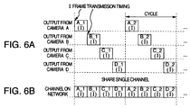
- Fig. 6A schematically shows the image signals transmitted from the cameras 10.
- the channel switch 42 is controlled by the timing controller 34 so that the I frames are sequentially switched from the cameras A-D to receive the I frames in accordance with the established transmission timings of I frames from the cameras A-D of the camera 10 without buffering the received image signals.
- the I frames from the cameras A-D are arranged in time series within one cycle.
- Fig. 6B shows the I frames received by the switching operation. The received I frames are temporarily stored in the transmission buffer 29, and then supplied through the network 36 to the recorder where they are recorded.
- the image signals from a plurality of cameras 10 are received by the channel switch 42, a single channel are shared in a time sharing manner by a plurality of cameras with transmission timings of I frames shifted because a certain one of the transmission timings of I frames limits an operation of the switcher to reception of only the image signal from one camera. In this event, only the I frames from a plurality of cameras 10 are transmitted with transmission timings shifted, and received on a single channel of the switcher in a time sharing manner.
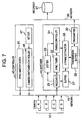
- Fig. 7 is a block diagram of a monitoring system according to the third embodiment of the invention that has the controller provided separately from the switcher.
- reference numeral 10 represents cameras having MPEG outputs, 44 a switcher for switching the I frames of the image signals received from the plurality of cameras, and 45 a controller for controlling the system.
- reference numeral 37 designates a recorder for recording the image data, and 15 and 36 networks through which the cameras 10, switcher 44, controller 45 and recorder 37 are connected together to transmit and receive data.
- the switcher 44 has fundamentally the same construction as the switcher 25 used in the above first embodiment, but does not have the synchronizing master clock 31 for controlling the system and the camera controller 35.
- the controller 45 has the synchronizing master clock 31, a camera/switcher controller 46 for sending an operation command to the cameras 10 and a switcher 44, and a setter 47 for setting an operations of the functional elements of the whole system.
- the switcher 44 is constructed to receive a setting command from the controller 45 through the network 15 and change the settings.
- the controller 45 is not necessarily separately provided as an independent apparatus, but is provided within one of the cameras 10 or within the recorder or another apparatus on the network as in the first embodiment in which the control function was installed within the switcher 25.
- the second embodiment is also modified in the same manner.
- the camera 10 is provided as slave apparatus as in the above embodiment, but in this case a buffer for temporarily storing the image signals and an I frame extractor for extracting the I frames from the image signals stored in this buffer are provided in the camera 10.
- the camera 10 transmits to the switcher 25 or 40 only the I frames that were already extracted and buffered in the camera 10.
- the buffer and I-frame extractor are provided between the coder 13 and the transmission buffer 14 in the structure of camera 10 shown in Fig. 1 so that the output data from the I-frame extractor are transferred to the transmission buffer 14.
- a digital monitoring system is constructed in which a plurality of digital cameras that are synchronized are connected to the switcher so that the image signals from the cameras are switched.
- transmission timings of I frames from the digital cameras and a transmission cycle are set, and the image signals of one cycle from the cameras are buffered so that only the necessary I frames are extracted. Therefore, even though the digital image signals include frames depending upon other frames such as P frame and B frame, only the necessary I frames are switched for reception.
- the transmission timings of I frames from the cameras are shifted, while the switcher switches the image signals from the cameras in accordance with the transmission timings of I frames. Therefore, even though digital-type cameras are used in the monitoring system, the image signals from the digital cameras are switched by frame switching with high efficiency, and the necessary frames are transferred to the recorder or reproducer by frame switching with less buffer and delay.
Applications Claiming Priority (2)
| Application Number | Priority Date | Filing Date | Title |
|---|---|---|---|
| JP12495299 | 1999-04-30 | ||
| JP12495299A JP4287538B2 (ja) | 1999-04-30 | 1999-04-30 | 画像信号切替方法及び装置並びにこれを用いたデジタル撮像カメラ及び監視システム |
Publications (3)
| Publication Number | Publication Date |
|---|---|
| EP1049333A2 true EP1049333A2 (de) | 2000-11-02 |
| EP1049333A3 EP1049333A3 (de) | 2004-01-02 |
| EP1049333B1 EP1049333B1 (de) | 2008-01-02 |
Family
ID=14898283
Family Applications (1)
| Application Number | Title | Priority Date | Filing Date |
|---|---|---|---|
| EP00109020A Expired - Lifetime EP1049333B1 (de) | 1999-04-30 | 2000-04-27 | Schaltung zwischen digitalen Kameras in einem Überwachungssystem |
Country Status (8)
| Country | Link |
|---|---|
| US (1) | US6791602B1 (de) |
| EP (1) | EP1049333B1 (de) |
| JP (1) | JP4287538B2 (de) |
| CN (2) | CN100444618C (de) |
| AU (1) | AU770177B2 (de) |
| CA (1) | CA2307523C (de) |
| DE (1) | DE60037611T2 (de) |
| TW (1) | TW545048B (de) |
Cited By (5)
| Publication number | Priority date | Publication date | Assignee | Title |
|---|---|---|---|---|
| WO2003007613A2 (en) * | 2001-07-11 | 2003-01-23 | Motorola Inc | Video transmission system video transmission unit and methods of encoding decoding video data |
| WO2003032641A2 (de) * | 2001-10-04 | 2003-04-17 | Siemens Aktiengesellschaft | System und verfahren zum übertragen digitaler daten |
| EP1453318A1 (de) * | 2003-02-28 | 2004-09-01 | Shimadzu Corporation | System für Hochgeschwindigkeitsfotografie und photographisches Steuergerät |
| EP1596602A2 (de) * | 2004-05-13 | 2005-11-16 | Canon Kabushiki Kaisha | Datenverarbeitungsgerät |
| EP3214839A4 (de) * | 2014-11-28 | 2017-09-06 | Huawei Technologies Co. Ltd. | Verfahren und vorrichtung zur übertragung mehrerer videoströme |
Families Citing this family (34)
| Publication number | Priority date | Publication date | Assignee | Title |
|---|---|---|---|---|
| US20070107029A1 (en) * | 2000-11-17 | 2007-05-10 | E-Watch Inc. | Multiple Video Display Configurations & Bandwidth Conservation Scheme for Transmitting Video Over a Network |
| JP3787498B2 (ja) * | 2001-02-13 | 2006-06-21 | キヤノン株式会社 | 撮像装置及び撮像システム |
| JP3981658B2 (ja) * | 2003-09-30 | 2007-09-26 | 松下電器産業株式会社 | 画像処理方法および画像処理装置 |
| JP4220883B2 (ja) * | 2003-11-05 | 2009-02-04 | 本田技研工業株式会社 | フレームグラバ |
| FI20031657A (fi) * | 2003-11-14 | 2005-05-15 | Nokia Corp | Langaton monikamerajärjestelmä |
| US8780957B2 (en) | 2005-01-14 | 2014-07-15 | Qualcomm Incorporated | Optimal weights for MMSE space-time equalizer of multicode CDMA system |
| AR052601A1 (es) | 2005-03-10 | 2007-03-21 | Qualcomm Inc | Clasificacion de contenido para procesamiento de multimedia |
| WO2006132029A1 (ja) * | 2005-06-07 | 2006-12-14 | Matsushita Electric Industrial Co., Ltd. | 監視システム、監視方法及びカメラ端末 |
| CN101263548B (zh) * | 2005-09-15 | 2010-05-26 | 夏普株式会社 | 影像传送装置和使用该装置的显示系统 |
| US8879857B2 (en) * | 2005-09-27 | 2014-11-04 | Qualcomm Incorporated | Redundant data encoding methods and device |
| US8654848B2 (en) * | 2005-10-17 | 2014-02-18 | Qualcomm Incorporated | Method and apparatus for shot detection in video streaming |
| US8948260B2 (en) | 2005-10-17 | 2015-02-03 | Qualcomm Incorporated | Adaptive GOP structure in video streaming |
| US20070206117A1 (en) * | 2005-10-17 | 2007-09-06 | Qualcomm Incorporated | Motion and apparatus for spatio-temporal deinterlacing aided by motion compensation for field-based video |
| JP4869256B2 (ja) * | 2006-01-13 | 2012-02-08 | パナソニック株式会社 | 無線通信基地局装置および同期チャネル信号送信方法 |
| WO2007080978A1 (ja) * | 2006-01-13 | 2007-07-19 | Matsushita Electric Industrial Co., Ltd. | 無線通信基地局装置および無線通信方法 |
| JP4704220B2 (ja) * | 2006-01-25 | 2011-06-15 | 三菱電機株式会社 | カメラ装置及び映像監視システム |
| JP2007201995A (ja) * | 2006-01-30 | 2007-08-09 | Matsushita Electric Ind Co Ltd | 映像データ転送処理装置および監視カメラシステム |
| US9131164B2 (en) | 2006-04-04 | 2015-09-08 | Qualcomm Incorporated | Preprocessor method and apparatus |
| ES2327152T3 (es) * | 2006-07-13 | 2009-10-26 | Axis Ab | Memoria intermedia de video de pre-alarma mejorada. |
| JP4099211B1 (ja) * | 2007-10-29 | 2008-06-11 | イメージニクス株式会社 | 映像切替器と映像切替方法 |
| CN101540899B (zh) * | 2008-03-19 | 2012-02-29 | 上海贝尔阿尔卡特股份有限公司 | 流媒体系统中的i帧解析方法和i帧解析器 |
| JP4618325B2 (ja) * | 2008-04-28 | 2011-01-26 | ソニー株式会社 | 情報処理装置及び情報処理方法並びにプログラム |
| JP5526638B2 (ja) * | 2008-10-30 | 2014-06-18 | 株式会社Jvcケンウッド | ワイヤレス画像伝送装置およびワイヤレス画像伝送方法 |
| JP4580448B2 (ja) * | 2009-01-23 | 2010-11-10 | パナソニック株式会社 | 画像信号切替方法及び装置並びにこれを用いたデジタル撮像カメラ及び監視システム |
| CN101854382A (zh) * | 2010-04-26 | 2010-10-06 | 上海乐毅信息科技有限公司 | 用于监控视频在3g网络传输的优化方法 |
| CN101867796B (zh) * | 2010-07-09 | 2013-08-14 | 浙江宇视科技有限公司 | 一种视频监控的方法和设备 |
| JP5316588B2 (ja) * | 2011-05-30 | 2013-10-16 | 沖電気工業株式会社 | 映像配信システム及び方法 |
| JP5929358B2 (ja) * | 2012-03-15 | 2016-06-01 | ソニー株式会社 | 画像伝送システムおよび画像伝送方法 |
| CN102801956B (zh) * | 2012-04-28 | 2014-12-17 | 武汉兴图新科电子股份有限公司 | 一种网络视频监控装置及方法 |
| JP6116192B2 (ja) * | 2012-11-07 | 2017-04-19 | 株式会社イマジオム | 動画処理装置、カメラ監視システム、プログラム |
| US9041813B1 (en) * | 2014-02-14 | 2015-05-26 | Maxim Integrated Products, Inc. | Multiple camera synchronization system |
| DE102015212218A1 (de) * | 2015-06-30 | 2017-01-05 | Robert Bosch Gmbh | Dezentral synchronisiertes Multisensorsystem |
| US10154225B2 (en) | 2016-11-18 | 2018-12-11 | Electronics & Telecommunications Research Institute | Frame grabber, image processing system including the same, and image processing method using the frame grabber |
| CN111741276B (zh) * | 2020-08-28 | 2020-12-04 | 浙江大华技术股份有限公司 | 一种视频设备发送关键帧的方法、视频设备和存储装置 |
Citations (2)
| Publication number | Priority date | Publication date | Assignee | Title |
|---|---|---|---|---|
| EP0895417A2 (de) * | 1997-08-01 | 1999-02-03 | Matsushita Electric Industrial Co., Ltd | Videoüberwachungssystem zur Überwachung einer Vielzahl von Orten |
| EP0982950A2 (de) * | 1998-08-24 | 2000-03-01 | Sony Corporation | Elektronische Videokamera mit MPEG Kodierer |
Family Cites Families (14)
| Publication number | Priority date | Publication date | Assignee | Title |
|---|---|---|---|---|
| JPH066265A (ja) * | 1992-06-15 | 1994-01-14 | Nippon Telegr & Teleph Corp <Ntt> | 等化器 |
| JP3191439B2 (ja) | 1992-08-31 | 2001-07-23 | ソニー株式会社 | 符号化画像信号切換装置 |
| JP2897543B2 (ja) * | 1992-09-03 | 1999-05-31 | 松下電器産業株式会社 | 符号化装置 |
| US5625410A (en) * | 1993-04-21 | 1997-04-29 | Kinywa Washino | Video monitoring and conferencing system |
| JPH07212748A (ja) * | 1994-01-25 | 1995-08-11 | Sony Corp | 監視カメラシステム |
| JPH0816943A (ja) * | 1994-06-27 | 1996-01-19 | Atsumi Electron Corp Ltd | 監視カメラ |
| JPH0884323A (ja) * | 1994-09-13 | 1996-03-26 | Nec Eng Ltd | 映像信号処理装置 |
| US6208376B1 (en) * | 1996-04-22 | 2001-03-27 | Canon Kabushiki Kaisha | Communication system and method and storage medium for storing programs in communication system |
| US5867484A (en) * | 1997-01-31 | 1999-02-02 | Intellect Network Technologies | Switchable multi-drop video distribution system |
| US6091455A (en) * | 1997-01-31 | 2000-07-18 | Hughes Electronics Corporation | Statistical multiplexer for recording video |
| JPH10257478A (ja) * | 1997-03-14 | 1998-09-25 | Canon Inc | 撮像装置および監視システム |
| JPH1169299A (ja) * | 1997-08-26 | 1999-03-09 | Toshiba Corp | 双方向データ多重型フレームスイッチャーシステム |
| US6167084A (en) * | 1998-08-27 | 2000-12-26 | Motorola, Inc. | Dynamic bit allocation for statistical multiplexing of compressed and uncompressed digital video signals |
| EP0982952A3 (de) * | 1998-08-28 | 2000-05-17 | Hitachi, Ltd. | Bewegtbild-Aufnahme/Wiedergabe-System |
-
1999
- 1999-04-30 JP JP12495299A patent/JP4287538B2/ja not_active Expired - Fee Related
-
2000
- 2000-04-20 US US09/553,150 patent/US6791602B1/en not_active Expired - Lifetime
- 2000-04-26 TW TW089107920A patent/TW545048B/zh not_active IP Right Cessation
- 2000-04-27 DE DE60037611T patent/DE60037611T2/de not_active Expired - Lifetime
- 2000-04-27 AU AU30165/00A patent/AU770177B2/en not_active Ceased
- 2000-04-27 EP EP00109020A patent/EP1049333B1/de not_active Expired - Lifetime
- 2000-04-28 CA CA2307523A patent/CA2307523C/en not_active Expired - Fee Related
- 2000-04-30 CN CNB2005100795921A patent/CN100444618C/zh not_active Expired - Lifetime
- 2000-04-30 CN CNB001082221A patent/CN100387049C/zh not_active Expired - Lifetime
Patent Citations (2)
| Publication number | Priority date | Publication date | Assignee | Title |
|---|---|---|---|---|
| EP0895417A2 (de) * | 1997-08-01 | 1999-02-03 | Matsushita Electric Industrial Co., Ltd | Videoüberwachungssystem zur Überwachung einer Vielzahl von Orten |
| EP0982950A2 (de) * | 1998-08-24 | 2000-03-01 | Sony Corporation | Elektronische Videokamera mit MPEG Kodierer |
Cited By (11)
| Publication number | Priority date | Publication date | Assignee | Title |
|---|---|---|---|---|
| WO2003007613A2 (en) * | 2001-07-11 | 2003-01-23 | Motorola Inc | Video transmission system video transmission unit and methods of encoding decoding video data |
| WO2003007613A3 (en) * | 2001-07-11 | 2003-05-22 | Motorola Inc | Video transmission system video transmission unit and methods of encoding decoding video data |
| AU2002321220B2 (en) * | 2001-07-11 | 2008-01-10 | Motorola Solutions, Inc. | Video transmission system video transmission unit and methods of encoding decoding video data |
| WO2003032641A2 (de) * | 2001-10-04 | 2003-04-17 | Siemens Aktiengesellschaft | System und verfahren zum übertragen digitaler daten |
| WO2003032641A3 (de) * | 2001-10-04 | 2003-07-17 | Siemens Ag | System und verfahren zum übertragen digitaler daten |
| EP1453318A1 (de) * | 2003-02-28 | 2004-09-01 | Shimadzu Corporation | System für Hochgeschwindigkeitsfotografie und photographisches Steuergerät |
| EP1596602A2 (de) * | 2004-05-13 | 2005-11-16 | Canon Kabushiki Kaisha | Datenverarbeitungsgerät |
| EP1596602A3 (de) * | 2004-05-13 | 2008-11-05 | Canon Kabushiki Kaisha | Datenverarbeitungsgerät |
| US7725610B2 (en) | 2004-05-13 | 2010-05-25 | Canon Kabushiki Kaisha | Data processing apparatus that transmits and receives moving image data to and from an external device through a transmission path |
| EP3214839A4 (de) * | 2014-11-28 | 2017-09-06 | Huawei Technologies Co. Ltd. | Verfahren und vorrichtung zur übertragung mehrerer videoströme |
| US10079997B2 (en) | 2014-11-28 | 2018-09-18 | Huawei Technologies Co., Ltd. | Multi-video stream transmission method and device |
Also Published As
| Publication number | Publication date |
|---|---|
| CA2307523C (en) | 2011-08-23 |
| AU770177B2 (en) | 2004-02-12 |
| JP2000316112A (ja) | 2000-11-14 |
| TW545048B (en) | 2003-08-01 |
| CN1272748A (zh) | 2000-11-08 |
| EP1049333B1 (de) | 2008-01-02 |
| CN100387049C (zh) | 2008-05-07 |
| CN1700743A (zh) | 2005-11-23 |
| DE60037611T2 (de) | 2009-01-08 |
| EP1049333A3 (de) | 2004-01-02 |
| US6791602B1 (en) | 2004-09-14 |
| CA2307523A1 (en) | 2000-10-30 |
| JP4287538B2 (ja) | 2009-07-01 |
| CN100444618C (zh) | 2008-12-17 |
| DE60037611D1 (de) | 2008-02-14 |
| AU3016500A (en) | 2000-11-02 |
Similar Documents
| Publication | Publication Date | Title |
|---|---|---|
| US6791602B1 (en) | Frame switcher and method of switching, digital camera and monitoring system | |
| US6529236B1 (en) | Digital camera for outputting digital image signals and image reproducing device connectable thereof | |
| JP2000316112A5 (de) | ||
| US8130279B2 (en) | Image sensing apparatus sensing moving and still images, method thereof, storage medium and computer program | |
| JP2873046B2 (ja) | 画像信号処理装置 | |
| JP2001125612A (ja) | 設備ロギング装置 | |
| US20030081564A1 (en) | Wireless transmission and recording of images from a video surveillance camera | |
| RU96111973A (ru) | Способ и устройство передачи дополнительных сигналов по телевизионным каналам и применение способа для передачи информации | |
| JP2002112257A (ja) | 映像圧縮伝送装置および方法 | |
| JP4580448B2 (ja) | 画像信号切替方法及び装置並びにこれを用いたデジタル撮像カメラ及び監視システム | |
| JP4360337B2 (ja) | 撮像素子の駆動制御方法及び撮像装置 | |
| KR100439023B1 (ko) | 디지털 영상 감시시스템 | |
| KR100479802B1 (ko) | 분산처리형 디지털 비디오 레코더 | |
| JPH07322238A (ja) | ディジタル映像信号多重伝送方法およびその装置 | |
| KR100320151B1 (ko) | 다중 영상신호저장 제어장치 | |
| KR200182088Y1 (ko) | 다중 영상신호저장 제어장치 | |
| JP2001268557A (ja) | ビデオ信号の処理装置および処理方法 | |
| JPH11341354A (ja) | 映像切換装置とその装置を用いた映像監視システム | |
| JPH1118082A (ja) | 画像信号処理装置及び方法 | |
| JPS62260487A (ja) | 画像通信制御方式 | |
| JP2007228500A (ja) | 多チャンネル動画の同期記録装置 | |
| JP2017188831A (ja) | 画像記録装置及び画像記録装置の制御方法 | |
| US20070115393A1 (en) | Video capture system | |
| WO2000040022A2 (en) | Method of and device for video image capturing, storage and processing | |
| JPH11275522A (ja) | デジタルvtr |
Legal Events
| Date | Code | Title | Description |
|---|---|---|---|
| PUAI | Public reference made under article 153(3) epc to a published international application that has entered the european phase |
Free format text: ORIGINAL CODE: 0009012 |
|
| AK | Designated contracting states |
Kind code of ref document: A2 Designated state(s): AT BE CH CY DE DK ES FI FR GB GR IE IT LI LU MC NL PT SE |
|
| AX | Request for extension of the european patent |
Free format text: AL;LT;LV;MK;RO;SI |
|
| PUAL | Search report despatched |
Free format text: ORIGINAL CODE: 0009013 |
|
| AK | Designated contracting states |
Kind code of ref document: A3 Designated state(s): AT BE CH CY DE DK ES FI FR GB GR IE IT LI LU MC NL PT SE |
|
| AX | Request for extension of the european patent |
Extension state: AL LT LV MK RO SI |
|
| RIC1 | Information provided on ipc code assigned before grant |
Ipc: 7H 04N 7/24 A Ipc: 7H 04N 7/18 B |
|
| 17P | Request for examination filed |
Effective date: 20040315 |
|
| AKX | Designation fees paid |
Designated state(s): DE FR GB NL |
|
| 17Q | First examination report despatched |
Effective date: 20041115 |
|
| 17Q | First examination report despatched |
Effective date: 20041115 |
|
| GRAP | Despatch of communication of intention to grant a patent |
Free format text: ORIGINAL CODE: EPIDOSNIGR1 |
|
| GRAS | Grant fee paid |
Free format text: ORIGINAL CODE: EPIDOSNIGR3 |
|
| GRAA | (expected) grant |
Free format text: ORIGINAL CODE: 0009210 |
|
| AK | Designated contracting states |
Kind code of ref document: B1 Designated state(s): DE FR GB NL |
|
| REG | Reference to a national code |
Ref country code: GB Ref legal event code: FG4D |
|
| REF | Corresponds to: |
Ref document number: 60037611 Country of ref document: DE Date of ref document: 20080214 Kind code of ref document: P |
|
| ET | Fr: translation filed | ||
| PLBE | No opposition filed within time limit |
Free format text: ORIGINAL CODE: 0009261 |
|
| STAA | Information on the status of an ep patent application or granted ep patent |
Free format text: STATUS: NO OPPOSITION FILED WITHIN TIME LIMIT |
|
| RAP2 | Party data changed (patent owner data changed or rights of a patent transferred) |
Owner name: PANASONIC CORPORATION |
|
| 26N | No opposition filed |
Effective date: 20081003 |
|
| NLT2 | Nl: modifications (of names), taken from the european patent patent bulletin |
Owner name: PANASONIC CORPORATION Effective date: 20081119 |
|
| PGFP | Annual fee paid to national office [announced via postgrant information from national office to epo] |
Ref country code: NL Payment date: 20090427 Year of fee payment: 10 |
|
| REG | Reference to a national code |
Ref country code: GB Ref legal event code: 746 Effective date: 20091221 |
|
| PGFP | Annual fee paid to national office [announced via postgrant information from national office to epo] |
Ref country code: GB Payment date: 20100325 Year of fee payment: 11 |
|
| PGFP | Annual fee paid to national office [announced via postgrant information from national office to epo] |
Ref country code: FR Payment date: 20100507 Year of fee payment: 11 |
|
| PGFP | Annual fee paid to national office [announced via postgrant information from national office to epo] |
Ref country code: DE Payment date: 20100430 Year of fee payment: 11 |
|
| REG | Reference to a national code |
Ref country code: NL Ref legal event code: V1 Effective date: 20101101 |
|
| PG25 | Lapsed in a contracting state [announced via postgrant information from national office to epo] |
Ref country code: NL Free format text: LAPSE BECAUSE OF NON-PAYMENT OF DUE FEES Effective date: 20101101 |
|
| REG | Reference to a national code |
Ref country code: DE Ref legal event code: R119 Ref document number: 60037611 Country of ref document: DE |
|
| REG | Reference to a national code |
Ref country code: DE Ref legal event code: R119 Ref document number: 60037611 Country of ref document: DE |
|
| GBPC | Gb: european patent ceased through non-payment of renewal fee |
Effective date: 20110427 |
|
| REG | Reference to a national code |
Ref country code: FR Ref legal event code: ST Effective date: 20111230 |
|
| PG25 | Lapsed in a contracting state [announced via postgrant information from national office to epo] |
Ref country code: FR Free format text: LAPSE BECAUSE OF NON-PAYMENT OF DUE FEES Effective date: 20110502 |
|
| PG25 | Lapsed in a contracting state [announced via postgrant information from national office to epo] |
Ref country code: GB Free format text: LAPSE BECAUSE OF NON-PAYMENT OF DUE FEES Effective date: 20110427 |
|
| PG25 | Lapsed in a contracting state [announced via postgrant information from national office to epo] |
Ref country code: DE Free format text: LAPSE BECAUSE OF NON-PAYMENT OF DUE FEES Effective date: 20111031 |