EP1049321B1 - Bilderzeugungsgerät - Google Patents
Bilderzeugungsgerät Download PDFInfo
- Publication number
- EP1049321B1 EP1049321B1 EP00107781A EP00107781A EP1049321B1 EP 1049321 B1 EP1049321 B1 EP 1049321B1 EP 00107781 A EP00107781 A EP 00107781A EP 00107781 A EP00107781 A EP 00107781A EP 1049321 B1 EP1049321 B1 EP 1049321B1
- Authority
- EP
- European Patent Office
- Prior art keywords
- density
- high density
- tone
- reference value
- image
- Prior art date
- Legal status (The legal status is an assumption and is not a legal conclusion. Google has not performed a legal analysis and makes no representation as to the accuracy of the status listed.)
- Expired - Lifetime
Links
- 238000012937 correction Methods 0.000 claims description 532
- 239000003086 colorant Substances 0.000 claims description 64
- 230000000694 effects Effects 0.000 claims description 45
- 239000007787 solid Substances 0.000 claims description 24
- 238000000034 method Methods 0.000 claims description 19
- 238000001514 detection method Methods 0.000 claims description 7
- 239000011159 matrix material Substances 0.000 claims description 3
- 238000012546 transfer Methods 0.000 description 31
- 230000009471 action Effects 0.000 description 22
- 238000004904 shortening Methods 0.000 description 19
- 238000006243 chemical reaction Methods 0.000 description 14
- 230000004044 response Effects 0.000 description 11
- 230000008859 change Effects 0.000 description 10
- 238000005513 bias potential Methods 0.000 description 9
- 230000008569 process Effects 0.000 description 8
- 230000000630 rising effect Effects 0.000 description 6
- 238000004140 cleaning Methods 0.000 description 5
- 239000000463 material Substances 0.000 description 4
- 230000003287 optical effect Effects 0.000 description 4
- 238000007796 conventional method Methods 0.000 description 3
- 230000001788 irregular Effects 0.000 description 3
- 230000015572 biosynthetic process Effects 0.000 description 2
- 230000006866 deterioration Effects 0.000 description 2
- 238000012423 maintenance Methods 0.000 description 2
- 239000011295 pitch Substances 0.000 description 2
- 238000004886 process control Methods 0.000 description 2
- 238000011282 treatment Methods 0.000 description 2
- 239000004642 Polyimide Substances 0.000 description 1
- 230000002411 adverse Effects 0.000 description 1
- 238000003384 imaging method Methods 0.000 description 1
- 229920001721 polyimide Polymers 0.000 description 1
- 230000001105 regulatory effect Effects 0.000 description 1
Images


Classifications
-
- H—ELECTRICITY
- H04—ELECTRIC COMMUNICATION TECHNIQUE
- H04N—PICTORIAL COMMUNICATION, e.g. TELEVISION
- H04N1/00—Scanning, transmission or reproduction of documents or the like, e.g. facsimile transmission; Details thereof
- H04N1/40—Picture signal circuits
- H04N1/407—Control or modification of tonal gradation or of extreme levels, e.g. background level
- H04N1/4076—Control or modification of tonal gradation or of extreme levels, e.g. background level dependent on references outside the picture
- H04N1/4078—Control or modification of tonal gradation or of extreme levels, e.g. background level dependent on references outside the picture using gradational references, e.g. grey-scale test pattern analysis
Definitions
- the present invention relates to an image forming apparatus in accordance with the precharacterizing part of claim 1 and to a method of maintaining an image density in an image forming apparatus at a specific level.
- An image forming apparatus of that kind is known from PATENT ABSTRACTS OF JAPAN vol. 1995, no. 04, 31 May 1995 (1995-05-31) & JP 07 020669 A (CANON INC), 24 January 1995 (1995-01-24).
- a color electrophotographic device includes a plurality of photosensitive drums 1 as shown in Figure 2 explaining an image forming apparatus of the present invention.
- Each photosensitive drum 1 is supported rotatably and driven to rotate in a direction indicated by an arrow by means of a driving device.
- each photosensitive drum 1 Provided sequentially around each photosensitive drum 1 are: a charging device 2 for charging the surface of the photosensitive drum 1 uniformly; exposing means 3 for exposing the surface of the photosensitive drum 1 to form a latent image; a developing device 4 for developing the latent image to a toner image; a transferring device 5 for transferring the toner image onto a transfer material; and a cleaning device 6 for cleaning residual toner on the surface of the photosensitive drum 1.
- the four photosensitive drums 1 are aligned in series, and provided with developing bathes respectively containing color toners: Y (yellow), M (Magenta), C (Cyan), and Bk (Black).
- the transferring device 5 is provided with a transfer belt 7 which is looped over a driving pulley and a slave pulley and run in a direction indicated by arrows. A recording medium as the transfer material is held electrostatically and thus transported by the transfer belt 7.
- Transfer chargers 8 are provided inside the loop of the transfer belt 7 so as to oppose the respective photosensitive drums 1, thereby transferring toner images formed on their respective photosensitive drums 1 onto the recording medium.
- the recording medium held by the transfer belt 7 passes by the four photosensitive drums 1 and further a fusing device 9, whereby the toner image is fused onto the same.
- a plurality of toner patterns each having a specific density are formed on the photosensitive drum 1 each time the power supply starts or a predetermined number of sheets are released. Then, the densities of these toner patterns are checked by a sensor, and differences between the checked densities and corresponding optimal densities, that is, the preset reference values, are found. Then, a density conversion table is created based on these differences. Thereafter, the density of the input image data is corrected based on the density conversion table thus created before the image is outputted.
- an image forming apparatus such as an electrophotographic device, outputs several kinds of images including solid (black-painted), line, half-tone, etc.
- Images vary when influenced by varying factors, namely, a series of charging, exposing, developing, and transferring actions in the electrophotographic process, and therefore, the density of an output image can not be maintained at a specific level without effecting a density correction.
- influence from the varying factors in the electrophotographic process varies with the kinds of images, and a density correction has to be controlled differently for each kind of images.
- the conventional image forming apparatus controls a quantity of toner to be adhered to the photosensitive drum 1 by detecting the density or a quantity of toner on a solid image, there rises a problem that a density of an entire output image can not be made uniform for each kind of images.
- Japanese Laid-open Patent Application No. 265571/1996 Japanese Laid-open Patent Application No. 265571/1996 (Japanese Official Gazette, Tokukaihei No. 8-265571, publishing date: October 11, 1996) discloses an image forming apparatus as follows.
- the image forming apparatus disclosed in the above publication forms two kinds of density detecting toner patterns, namely, a high density detecting toner pattern and a half-tone density toner pattern, by changing a developing bias, so that the density of an entire image having half-tones, etc. can be corrected adequately.
- the high density detecting toner pattern is detected by toner quantity detecting means composed of a reflection sensor, and the maximum toner quantity on the photosensitive drum is controlled by density correcting means.
- the half-tone detecting toner pattern is also detected by the toner quantity detecting means, and a toner quantity on the photosensitive drum for a half-tone density portion is adjusted under control of the density correcting means.
- the density correcting means has the toner quantity detecting means detect the high density from the high density detecting toner pattern, compares the detected high density with the high density reference value, and effects the high density correction if there is a difference. Further, after the high density portion of the image is adjusted, the density correcting means has the toner quantity detecting means detect the half-tone density from the half-tone density detecting toner pattern, compares the detected half-tone density with the half-tone density reference value, and effects the half-tone density correction if there is a difference.
- Japanese Laid-open Patent Application No. 289148/1996 Japanese Laid-open Patent Application No. 289148/1996 (Japanese Official Gazette, Tokukaihei No. 8-289148, publishing date: November 1, 1996) discloses a half-tone density correction.
- a plurality of half-tone toner patterns of respective colors are formed on a transfer belt by changing a pulse width of a laser beam during the exposing action in the series of charging, exposing, developing, and transferring actions, and these patterns are checked sequentially by a density detecting sensor, whereby an optical density is detected from the checking results.
- the checked density values are compared with prestored target density values of their respective colors, and differences between the target density values and current density values are computed to update a half-tone table.
- the density correction using the toner patterns is effected by forming a plurality of toner patterns each time the power supply starts or a predetermined number of sheets are released.
- the conventional image forming apparatus not only effects the high density correction, but also adjusts the half-tone density, and therefore, the density correction takes a considerably long time. Consequently, the conventional image forming apparatus keeps the user waiting longer compared with an image forming apparatus which effects the high density correction alone, thereby posing a problem as not being user-friendly.
- the half-tone density is adjusted in addition to the high density correction, a larger quantity of toner is consumed in forming the half-tone density detecting toner patterns for the half-tone density adjustment, thereby increasing the cost undesirably.
- a first density conversion table used as a reference is created at the time of maintenance.
- a toner pattern is formed each time a predetermined number of copies are made, and the density of the toner pattern is checked, based on which a second density conversion table is created.
- a new density conversion table for use in actual image output is created based on the first and second density conversion tables.
- table values are set linearly with a certain gradient with reference to the neighboring middle density area.
- forming a toner pattern and checking the density thereof involves various kinds of treatments of the photosensitive body, developing device, sensor in the transferring device, etc.
- the density of the toner pattern may include noise for various reasons during these treatments.
- the density conversion table is created on the assumption that the detected density of the toner pattern is completely correct, an output image may be formed with a density at an incorrect level.
- the number of toner patterns is generally smaller than that of the levels of the output image density, and for this reason, a density conversion table covering all the levels is created by means of interpolation.
- a density conversion table is created incorrectly by means of interpolation, an output image may be formed with a density at an incorrect level.
- a color balance of the entire color image varies markedly with ambient temperature and humidity, and life characteristics of members involved in image formation.
- it is essential to judge variance in a color balance of the entire color image and correct the same.
- an image density varies with the foregoing varying factors whether in the high density area or half-tone density area, and the variance often differs significantly among colors.
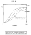
- the density may change from a density curve before replacing a member (indicated by an alternate long and short dash line) to a density curve after replacing a member (indicated by an alternate long and two short dashes line). In such a case, variance in a color balance cannot be judged precisely.
- Figure 13 shows the density change of only one color, but each color varies differently with ambient temperature and humidity, and the life characteristics of the members.
- a difference from the reference density is small in each color, when a toner image of each color is superimposed to form a multi-color image, a color balance of the resulting color image often varies.
- the image forming apparatus known from Patent Abstracts of Japan as cited above to the precharacterizing part of claim 1 is provided with a first control stage where the density of a specified density pattern formed on a medium is read and the maximum density is controlled based on the result, and a second control stage where a tone pattern formed on the medium is read and the half-tone control is performed based on the result.
- a first control mode is selected so as to execute the first and the second control stages and when a short time elapses, a second control mode is selected so as to execute only the first control stage.
- This known image forming apparatus does not describe that said imaging density correcting means determines on the basis of a result of the high density correction whether the half-tone density correction should be effected or not.
- the present invention according to claim 1 referring to an image forming apparatus and to claim 20 referring to a method of maintaining an image density at a specific level in an image forming apparatus is devised to solve the above problems, and therefore, has an object to provide an image forming apparatus which can maintain a density output of an entire image at a specific level for any kind of images including solid, line, half-tone, etc., while shortening the time required for a density correction and reducing a quantity of toner consumed for the density correction.
- an image forming apparatus of the present invention is an image forming apparatus furnished with:
- the following steps are carried out by the image density correcting section to maintain an image density at a specific level. That is, a predetermined high density detecting toner pattern is formed on the photosensitive body for the high density correction. Then, a value detected from the high density detecting toner pattern by a reflection toner sensor or the like is compared with the high density reference value, whereby a quantity of the high density correction is determined. In addition, a predetermined half-tone density detecting toner pattern is formed on the photosensitive body for a half-tone density correction. Then, a value detected from the half-tone density detecting toner pattern by the reflection sensor is compared with the half-tone density reference value, whereby a quantity of the half-tone density correction is determined.
- the image density correcting section determines whether the half-tone density correction should be effected or not based on the result of the high density correction.
- the half-tone density correction is not effected following each high density correction. Whether the half-tone density correction should be effected or not is judged based on the result of the high density correction, and the half-tone density correction is effected in accordance with the result, thereby making it possible to shorten the time required for the density correction and reduce a quantity of toner consumed for the density correction. In addition, because the half-tone density correction is effected only when it is absolutely necessary, high efficiency can be attained.
- the high density correction is effected by comparing the value detected from the high density detecting toner pattern by the density detecting sensor with the high density reference value.
- the density characteristics of the input image data can be corrected in response to variance of the density characteristics caused by circumstances, such as an applied voltage and a temperature rise during a series of charging, exposing, and developing actions in the electrophotographic process.
- circumstances such as an applied voltage and a temperature rise during a series of charging, exposing, and developing actions in the electrophotographic process.
- it has become possible to provide an image forming apparatus which can maintain a density output of an entire image at a specific level for any kind of images including solid, line, and half-tone, etc. while shortening a time required for the density correction and reducing a quantity of toner consumed for the density correction.
- the present embodiment will describe a color electrophotographic device as an image forming apparatus, but the present invention is not limited to the foregoing and can be also applied to a monochromatic electrophotographic device as an image forming device. Further, the present invention can be applied to other image forming apparatuses employing the electrophotographic technique, such as a copy machine, a laser beam printer, and a facsimile machine.
- a color electrophotographic device of the present embodiment includes, as shown in Figure 2, a plurality of photosensitive drums 1. Each photosensitive drum 1 is supported rotatably and driven to rotate in a direction indicated by an arrow by means of a driving device.
- each photosensitive drum 1 Provided sequentially around each photosensitive drum 1 are: a charging device 2 for changing the surface of the photosensitive drum 1 uniformly; an exposing device 3 for exposing the surface of the photosensitive drum 1 to form a latent image; a developing device 4 for developing the latent image to a toner image; a transferring device 5 for transferring the toner image onto a transfer material; and a cleaning device 6 for cleaning residual toner on the surface of the photosensitive drum 1.
- the four photosensitive drums 1 are aligned in series, and provided with developing bathes respectively containing color toners: Y (yellow), M (Magenta), C (Cyan), and Bk (Black).
- the transferring device 5 is provided with a transfer belt 7 which is looped over a driving pulley and a slave pulley and run in a direction indicated by arrows. A recording medium as the transfer material is held electrostatically and thus transported by the transfer belt 7.
- Transfer chargers 8 are provided inside the loop of the transfer belt 7 so as to oppose the respective photosensitive drums 1, and transfer toner images formed on the photosensitive drums 1 onto a recording medium electrostatically held and thus transported by the transfer belt 7.
- a cleaning member, an erasing member for removing charges accumulated on the transfer belt 7, etc. are also provided in the inside and outside of the loop of the transfer belt 7.
- the recording medium held by the transfer belt 7 passes by the four photosensitive drums 1 and further a fusing device 9, whereby the toner image is fused onto the same.
- the color electrophotographic device of the present embodiment is provided with a density detecting sensor 10 serving as toner quantity detecting means at an adequate position below the transfer belt 7 to oppose the same.
- the density detecting sensor 10 is a reflection sensor, and as shown in Figure 3, it includes a light emitting element 11, an irregular reflection light receiving element 12, and a regular reflection light receiving element 13, so that both a color density and a black density can be detected.
- the transfer belt 7 is made of denatured polyimide to give a large reflectance difference to the toner, and regular reflectance of 10% or greater is given by applying mirror finishing on the surface thereof.
- the color electrophotographic device of the present embodiment corrects the image density of an output image adequately by forming two kinds of density detecting toner patterns, namely, a high density detecting toner pattern and a half-tone density detecting toner pattern, on the photosensitive drums 1 by changing a developing bias.
- Each of the high density detecting toner pattern and half-tone density detecting toner pattern is formed as a reference value whenever an image is formed.
- the high density detecting toner pattern and half-tone density detecting toner pattern are formed on a non- image-forming area of the photosensitive drums 1.
- the high density detecting toner pattern is formed in the form of a solid image, whereby a control is effected under the condition that the maximum toner quantity is set as an adequate quantity.
- a plurality of the half-tone density detecting toner patterns are formed with different densities each in a 3 ⁇ 3 pixel matrix.
- a certain number of dots are formed by toner in a specific area in the 3 ⁇ 3 pixel matrix, and by sequentially increasing the number of dots, toner patterns having densities at a plurality of levels (from the low density area to near the high density area of a solid image) are formed in the half-tone density area. Consequently, a toner quantity in the half-tone density area can be controlled.
- each photosensitive drum 1 is charged, exposed, and developed, during which predetermined high density detecting toner patterns of respective colors described below are formed on the respective photosensitive drums 1 by changing the developing bias.
- the high density detecting toner patterns of respective colors thus formed are transferred onto the transfer belt 7, and checked sequentially by the density detecting sensor 10 to determine a correction quantity.
- Equation (1) the reflectance on the transfer belt 7 can be regulated, and the density can be read in a stable manner.
- the half-tone density correction is not effected following each high density correction. That is, as shown in Figure 1, whether conditions for effecting the half-tone density correction are established or not is judged (S4), and the half-tone density correction is effected only when the conditions are established.
- the half-tone density correction is effected only when a difference between the developing bias set in the preceding high density correction and the developing bias set in the current high density correction exceeds a difference reference value.
- the result of the current high density correction that is, the developing bias voltage value determined in the current high density correction is compared with the result of the preceding high density correction, that is, the developing bias voltage value determined in the preceding high density correction, and the half-tone density correction is effected following the high density correction only when the difference reaches or exceeds the preset difference reference value.
- the developing bias ⁇ 50V is given as the difference reference value, and the half-tone density correction is effected only when the difference reaches or exceeds the developing bias ⁇ 50V.
- ⁇ 50V is given as the difference reference value on the assumption that it is appropriate to effect at least the half-tone density correction following the high density correction when the difference reference value reaches or exceeds ⁇ 50V.
- the difference reference value is not limited to ⁇ 50V.
- a plurality of half-tone density detecting toner patterns of respective colors having different densities are formed on the transfer belt 7 by modulating the pulse width of the laser beam at the time of exposure during a series of the charging, exposing, developing, and transferring actions (S5). Then, the half-tone density detecting toner patterns are sequentially checked by the density detecting sensor 10 (S6), and a laser PMW (Pulse Wave Modulation) value is computed from the checking results to detect an optical density (S7) in the same manner as described in the high density correction.
- PMW Pulse Wave Modulation
- the detected values are compared with the prestored half-tone density reference values of respective colors, and a difference between the half-tone density reference value and a current value is computed, based on which a half-tone density correction table is updated (S8). Thereafter, the half-tone density is corrected based on the half-tone density correction table thus updated. It should be appreciated that the initial table for the half-tone density reference values is created at the time of maintenance.
- A' is given as the current detection value of the density detecting sensor 10 and B' is given as the half-tone density reference value at a laser duty A (laser output). Then, the half-tone density reference value B' is secured as a sensor value by shifting the laser duty A to a laser duty B, whereby the image density is maintained.
- the half-tone density of the image can be also maintained at the specific level.
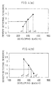
- a developing bias voltage value of -300V is given as the initial high density reference value when the color electrophotographic device starts to rise.
- the high density correction is effected at a time t1, and the developing bias voltage is changed to - 320 as the result of the high density correction.
- ⁇ 20V is given as a difference from the developing bias voltage value of -300V adopted as the preceding high density reference value.
- the high density correction is effected again at a time t2, and the developing bias voltage value is changed to -260V.
- ⁇ 60V is given as a difference from the developing bias voltage value of -320V adopted as the high density reference value as the result of the preceding high density correction.
- the half-tone density correction is effected.
- the high density correction is effected again at a time t3.
- the developing bias voltage value at this point is -270V and ⁇ 10V is given as a difference from the developing bias voltage of -260V adopted as the preceding high density reference value.
- the difference reference value is 50V or greater
- the high density correction is effected again at a time t4.
- the developing bias voltage value is changed to -320V as the result, and ⁇ 50 is given as a difference from the developing bias voltage value of -270V adopted as the preceding high density reference value.
- the difference reference value is 50V or greater.
- the above correction method exploits the fact that when the density characteristics vary markedly in response to the developing bias, the density characteristics are most likely vary in response to a laser output.
- the density of an entire image can be maintained constantly at a specific level.
- the half-tone density correction is not effected when unnecessary, and therefore, can be effected efficiently.
- the time required for the density correction can be shortened and a quantity of toner consumed for the density correction can be reduced.
- the high density reference value is compared with the result of the current high density correction, and if a difference in at least one color reaches or exceeds the difference reference value, the half-tone density correction is effected for all the colors following the high density correction.
- the unillustrated image density correcting means carries out the followings to maintain the image density at a specific level. That is, predetermined high density detecting toner patterns are formed on the photosensitive drums 1 by changing the developing bias for the high density correction. Then, the detected values of the high density detecting toner patterns detected by the density detecting sensor 10 are compared with the high density reference values, and a quantity of the high density correction is determined. Also, predetermined half-tone density detecting toner patterns are formed on the photosensitive drums 1 by changing the developing bias for the half-tone density detection. Then, the detected values of the half-tone density detecting toner patterns detected by the density detecting sensor 10 are compared with the half-tone density reference values, and a quantity of the half-tone density correction is determined.
- the density of an entire image can be maintained constantly at a specific level.
- the image density correcting means adopts the result of the preceding high density correction as the high density reference value, and compares the same with the result of the current high density correction. Then, the image density correcting means effects the half-tone density correction by raising/dropping the surface potential of the photosensitive drums 1 by adjusting the laser output during the exposure following the high density correction only when the difference reaches or exceeds the preset difference reference value.
- the high density reference value is updated to the result of the latest high density correction each time the high density correction is effected, and the result of the current high density correction is compared with the updated high density reference value.
- the half-tone density correction is not effected following each high density correction.
- the half-tone density correction is effected following the high density correction only when the updated high density reference value is compared with the result of the current high density correction and a difference reaches or exceeds the preset difference reference value.
- the half-tone density correction is effected only when there is a considerable difference from the updated high density reference value.
- high efficiency can be attained.
- the high density reference value is updated each time the high reference correction is effected.
- the density characteristics of the input image data can be corrected in response to variance of the density characteristics caused by circumstances, such as an applied voltage and a temperature rise during a series of charging, exposing, and developing actions in the electrophotographic process.
- the image density correcting means compares the high density reference value with the result of the current high density correction when effecting the density correction of a color image, and the half-tone density correction is effected for all the colors following the high density correction when a difference in at least one color reaches or exceeds the difference reference value.
- the half-tone density correction is effected for all the colors following the high density correction when a difference in at least one color reaches or exceeds the difference reference value.
- the time required for the density correction be shortened, but also a quantity of toner consumed for the density correction can be reduced.
- the image density correction in the multi-color image forming apparatus is a crucial factor affecting a color balance. Hence, by effecting the half-tone density correction for all the colors even when the half-tone density correction is necessary for only one color, a color balance can be maintained in a reliable manner.
- a color electrophotographic device of the present embodiment determines whether the half-tone density correction should be effect or not from the result of the high density correction in the same manner as Embodiment 1 except that the difference reference value is set in a different manner.
- the result of the high density correction when the latest half-tone density correction was effected is adopted as the high density reference value, and the high density reference value thus adopted is compared with the result of the current high density correction. Then, the half-tone density correction is effected following the high density correction only when a difference reaches or exceeds a preset difference reference value.
- the high density developing bias voltage value set in the half-tone density correction when the latest half-tone density correction was effected is adopted as the high density reference value, and the half-tone density correction is effected only when a difference between the high density reference value thus adopted and the current developing bias voltage reaches or exceeds the difference reference value (herein ⁇ 50V).
- the density of an entire image can be maintained constantly at a specific level. Also, by determining whether the half-tone density correction should be effected or not based on the result of the highest density correction, the half-tone density correction is not effected when unnecessary, and therefore, can be effected efficiently. Hence, the time required for the density correction can be shortened and a quantity of toner consumed for the density correction can be reduced.
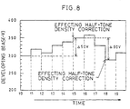
- the developing bias voltage value of -300V is given as the high density reference value at a time t0 when the color electrophotographic device starts to rise. It should be appreciated that, at this initial stage, the half-tone density correction is also effected.
- the high density correction is effected at times t1, t2, t3, and t4, and the developing bias voltage values of -320V, -310V, -330V, and -340V are given as the high density reference values, respectively.
- a difference from the developing bias voltage value of -300V adopted as the initial high density reference value is smaller than ⁇ 50V.
- the half-tone density correction is not effected.
- the high density correction is effected again at a time t5, and the developing bias voltage is changed to -350V, yielding a difference of ⁇ 50V from the developing bias voltage of -300V adopted as the initial high density reference value.
- the difference reference value is 50V or greater.
- the high density correction is effected again at times t6 and t7, and a difference from the developing bias voltage value of -350 adopted as the high density reference value when the latest half-tone density correction was effected (at time t5) is smaller than ⁇ 50.
- the difference reference value is 50V or greater are not satisfied, the half-tone density correction is not effected.
- the high density correction is effected again at time t8, and the developing bias voltage value is changed to -290V as a result.
- the correction result when the latest half-tone density correction was effected (at time t5) is adopted as the high density reference value, and ⁇ 60 is given as a difference from the developing bias voltage value of -350 adopted as the high density reference value.
- the difference reference value is 50V or greater.
- the image density correcting means compares the high density reference value with the result of the current high density correction, and effects the half-tone density correction following the high density correction only when the difference reaches or exceeds the preset difference reference value.
- the half-tone density correction is not effected following each high density correction, but effected following the high density correction only when the initial high density reference value is compared with the result of the current high density correction and a difference reaches or exceeds the preset difference reference value.
- the half-tone density correction should be effected or not is judged based on the result of the high density correction, and the half-tone density correction is effected in accordance with the result, the time required for the density correction can be shortened and a quantity of toner consumed for the density correction can be reduced.
- whether the half-tone density correction should be effected or not is determined by comparing the high density reference value with the result of the current high density correction, and then judging whether the difference reaches or exceeds the preset difference reference value.
- the half-tone density correction is effected only when there is a significant difference from the high density reference value.
- the half-tone density correction is effected only when it is absolutely necessary, high efficiency can be attained.
- the density characteristics of the input image data is corrected in response to variance of the density characteristics caused by an applied voltage or a temperature rise during a series of charging, exposing, and developing actions based on the initial high density reference value of the toner of each color before the image is outputted.
- the density characteristics of the input image data can be corrected in response to ideal density characteristics before the output.
- the image density correcting means adopts the result of the high density correction when the latest half-tone density correction was effected as the high density reference value, and compares the same with the result of the current high density correction. Then, the image density correcting means effects the half-tone density correction following the high density correction only when a difference reaches or exceeds the preset difference reference value.
- the result of the current high density correction is compared with the result of the high density correction when the latest half-tone density correction was effected, which is adopted as the high density reference value.
- the half-tone density correction is not effected following each high density correction, but effected following the high density correction only when the result of the high density correction when the latest half-tone density correction was effected, which is adopted as the high density reference value, is compared with the result of the current high density correction and a difference reaches or exceeds the preset difference reference value.
- the half-tone density correction should be effected or not is judged based on the result of the high density correction, and the half-tone density correction is effected in accordance with the result, the time required for the density correction can be shortened and a quantity of toner consumed for the density correction can be reduced.
- whether the half-tone density correction should be effected or not is determined by comparing the result of the high density correction when the latest half-tone density correction was effected, which is adopted as the high density reference value, with the result of the current high density correction, and then judging whether the difference reaches or exceeds the preset difference reference value.
- the half-tone density correction is effected only when the result of the current high density correction differs markedly from the high density reference value. Hence, because the half-tone density correction is effected only when it is absolutely necessary, high efficiency can be attained.
- the high density reference value is updated to the result of the high density correction when the latest half-tone density correction was effected.
- the high density reference value is compared with the result of the current high density correction, and the half-tone density correction is effected for all the colors following the high density correction if the difference in at least one color reaches or exceeds the difference reference value.
- the half-tone density correction is effected for all the colors following the high density correction when the difference in at least one color reaches or exceeds the difference reference value, not only can the time required for the density correction be shortened, but also a quantity of toner consumed for the density correction can be reduced.
- the image density correction in the multi-color image forming apparatus is a crucial factor affecting a color balance. Hence, by effecting the half-tone density correction for all the colors even when the half-tone density correction is necessary for only one color, a color balance can be maintained in a reliable manner.
- the present embodiment will describe a correcting method of the half-tone density.
- the half-tone density correction is composed of two steps: first and second steps.
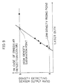
- first step a low density rising point and a high density saturation point are found.
- second step detailed data of these points are collected for approximation.
- the first step five kinds of half-tone density detecting toner patterns each having different density are formed on the transfer belt 7 through a series of the charging by changing a laser duty of the exposing device 3, exposing, developing, and transferring actions.
- the laser duty values are set in a range from 0 to 255, and in the present embodiment, set to 31, 47, 63, 79, and 255, for example.
- the low density rising point and high density saturation point are computed in the following manner.
- the output ratio a of the density detecting sensor 10 to give the laser duty 0 is a fixed value found without collecting data.
- 16 kinds of half-tone density detecting toner patterns are sequentially formed on the transfer belt 7, and detailed data of the points found in the first step are collected.
- one or more of these 16 kinds of half-tone density detecting toner patterns may be the same as the laser duties of 31, 47, 63, 79 and 255 found in the first step.
- the pitches of the laser duty is narrower around the inflection point used as the high density saturation point.
- 5% is given as the reference value in the low density area, for example, and data is approximated after the data of the half-tone density detecting toner pattern(s) showing less than 5% is deleted, so that an unstable sensor value at or around the low density rising point will not give any adverse effect to an output image.
- approximation is conducted for the data of the half-tone density detecting toner patterns from the point at which the sensor values of the density detecting sensor 10 start to rise continuously, so that irregularity of an approximation line can be reduced.
- the half-tone density curve thus obtained is compared with a target (initial) value of Figure 5 and a correction quantity is computed, based on which the half-tone table is updated.
- the half-tone density can be corrected in a short time and a high-quality image can be outputted.
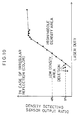
- Figures 9 and 10 show a relation between the laser duty and the output ratio of irregular reflection of the density detecting sensor 10 for a color image, and for this reason, the straight line is upward to the right. In case of a monochromatic image, the detection value of regular reflection from the density detecting sensor 10 is used, and for this reason, the straight line is downward to the right as shown in Figure 4(b).
- the image density correcting means effects the half-tone density correction by forming a plurality of half-tone density detecting toner patterns having different density levels from the low density area to near the high density area and comparing the same with the half-tone density reference value.
- the image density correcting means deletes any detected value equal to or below the preset low density area deleting reference value in the low density area, and effects the correction by a value found by linear approximation using the rest of the detected values.
- any detected value equal to or below the preset low density area deleting reference value is deleted in the low density area, and the linear approximation is conducted using the rest of the detected values.
- a required time can be shortened considerably compared with a case of creating a density conversion table covering all the levels by means of interpolation.
- the reflection point of detected values when the laser output is changed gradually from the lower end to the higher end is adopted. More specifically, in case of a color image, a point at which the detected values start to rise continuously is adopted, and in case of a monochromatic image, a point at which the detected values start to drop continuously is adopted.
- the detected values in the low density area which are not readily linear-approximated can be deleted in a reliable manner, and the detected values appropriate for the linear approximation can be left as many as possible.
- unillustrated image density correcting means compares the high density reference value with the result of the current high density correction for each color, and effects the half-tone density correction only when a total of the differences in all the colors reaches or exceeds a preset total difference reference value.
- the high density correction is effected to correct the developing bias potential for each of Y, M, C, and Bk.
- 300V is given as the high density reference value for the developing bias potential for each color.
- 100V is given as the total difference reference value as a total of the differences between the correction results of the developing bias and the high density reference value for all the four colors, and the half-tone density correction is effected only when the total difference reference value reaches or exceeds 100V.
- the half-tone density correction is effected if a difference between the developing bias and the high density reference value exceeds 50V at least in one color.
- the half-tone density correction is effected, because the total of the differences in all the four colors is 105V and exceeds the total difference reference value of 100V.
- the unillustrated image density correcting means compares the high density reference value with the result of the current high density correction for each color, and effects the half-tone density correction following the high density correction only when the total of differences in all the colors reaches or exceeds the preset total difference reference value.
- the density of an entire image can be maintained constantly at a specific level.
- the half-tone density correction is not effected when unnecessary, and therefore, can be effected efficiently in consideration of all the colors, thereby shortening the time required for the density correction and reducing a quantity of toner consumed for the density correction while improving the image quality.
- unillustrated image density correcting means compares the high density reference value with the result of the current high density correction for each color, and effects the half-tone density correction following the high density correction only when a difference of a monochromatic color alone reaches or exceeds a monochromatic difference reference value, or a total of differences in all the colors excluding the monochromatic color reaches or exceeds a preset color total difference reference value.
- the high density correction is effected and the developing bias potential is corrected for each of colors Y, M, C, and Bk.
- 300V is given as the high density reference value of the developing bias potential for each color.
- the half-tone density correction is effected if a difference between the high density reference value and the correction result of the developing bias for Bk reaches or exceeds 40V which is given as the monochromatic difference reference value, or a total of differences between the high density reference values and the correction results of the developing bias for the rest of three colors reaches or exceeds 80V which is given as the color total difference reference value.
- the unillustrated image density correcting means compares the high density reference value with the result of the current high density correction for each color, and effects the half-tone density correction following the high density correction only when a difference of a monochromatic color alone reaches or exceeds the monochromatic difference reference value, or a total of differences of colors excluding the monochromatic color reaches or exceeds the preset color total difference reference value.
- the density of an entire image can be maintained constantly at a specific level.
- the density correction is effected separately when the half-tone density of a color image is changed and when the half-tone density of a monochromatic image is changed.
- the half-tone density correction is effected efficiently only when necessary for either the monochromatic color or the rest of the colors by considering the monochromatic color or the reset of the colors, thereby shortening the time required for the density correction and reducing a quantity of toner consumed for the density correction while improving the image quality.
- unillustrated image density correcting means compares the high density reference value with the result of the current high density correction for each color, and effects the half-tone density correction following the high density correction only when a total of absolute values of the differences of all the colors reaches or exceeds a preset total absolute difference reference value.
- the high density correction is effected and the developing bias potential is corrected for each of colors Y, M, C, and Bk.
- 300V is given as the high density reference value of the developing bias potential for each color.
- the half-tone density correction is effected when a total of the absolute values of the differences between the reference value from the correction results of the developing bias for all the four colors reaches or exceeds 100V given as the absolute difference reference value.
- a total of the absolute values of the differences from the high density reference value is computed, and a total of 105V is obtained. Because the total of the absolute difference values of four colors exceeds 100V given as the absolute total difference reference value, the half-tone density reference value is effected for each color.
- the unillustrated image density correcting means compares the high density reference value with the result of the current high density correction for each color, and effects the half-tone density correction following the high density correction only when a total of absolute values of the differences of all the colors reaches or exceeds a preset total absolute difference reference value.
- the density of an entire image can be maintained constantly at a specific level.
- the half-tone density correction is not effected when unnecessary, and therefore, can be effected efficiently in consideration of all the colors, not only can the time required for the density correction be shortened, but also a quantity of toner consumed for the density correction can be reduced while improving the image quality.
- an image forming apparatus of the present invention is an image forming apparatus having image density correcting means for effecting (1) a high density correction, by which a predetermined high density detecting toner pattern is formed on a photosensitive body, and a quantity of the high density correction is determined by comparing a value detected from said high density detecting toner pattern by a reflection sensor with a high density reference value; and (2) a half-tone density correction, by which a predetermined half-tone density detecting toner pattern is formed on the photosensitive body, and a quantity of the half-tone density correction is determined by comparing a value detected from said half-tone density detecting toner pattern by the reflection sensor with a half-tone density reference value, arranged in such a manner that: said image density correcting means adopts a result of a preceding high density correction as said high density reference value, compares said high density reference value with a result of a current high density correction, and effects the half-tone density correction following the high density
- the image density correcting means in order to maintain the image density at a specific level, the followings are carried out by the image density correcting means. That is, a predetermined high density detecting toner pattern is formed on the photosensitive body for the high density correction. Then, a value detected from the high density detecting toner pattern by the reflection sensor is compared with the high density reference value, and a quantity of the high density correction is determined. Also, a predetermined half-tone density detecting toner pattern is formed on the photosensitive body for the half-tone density correction. Then, a value detected from the half-tone density detecting toner pattern by the reflection sensor is compared with the half-tone density reference value, and a quantity of the half-tone density correction is determined.
- the image density correcting means adopts the result of the preceding high density correction as the high density reference value, compares the same with the result of a current high density correction, and effects the half-tone density correction following the high density correction only when a difference reaches or exceeds the preset difference reference value.
- the high density reference value is updated to the result of the latest high density correction each time the high density correction is effected, and the result of the current high density correction is compared with the updated high density reference value.
- the half-tone density correction is not effected following each high density correction. That is, the updated high density reference value is compared with the result of the current high density correction, and the half-tone density correction is effected only when a difference reaches or exceeds the preset difference reference value.
- Whether the half-tone density correction should be effected or not is judged by comparing the updated high density reference value with the result of the current high density correction, and then judging whether a difference reaches or exceeds the preset difference reference value.
- the half-tone density correction is effected only when there is a significant difference from the updated high density reference value.
- high efficiency can be attained.
- the density characteristics of the input image data can be corrected in response to variance of the density characteristics caused by an applied voltage or a temperature rise during a series of charging, exposing, and developing actions in the electrophotographic process.
- an image forming device of the present invention is an image forming device having image density correcting means for effecting (1) a high density correction, by which a predetermined high density detecting toner pattern is formed on a photosensitive body, and a quantity of the high density correction is determined by comparing a value detected from said high density detecting toner pattern by a reflection sensor with a high density reference value; and (2) a half-tone density correction, by which a predetermined half-tone density detecting toner pattern is formed on the photosensitive body, and a quantity of the half-tone density correction is determined by comparing a value detected from said half-tone density detecting toner pattern by the reflection sensor with a half-tone density reference value, arranged in such a manner that: said image density correcting means compares said high density reference value with a result of a current high density correction, and effects the half-tone density correction following the high density correction only when a difference reaches or exceeds a preset difference reference value.
- the image density correcting means compares the high density reference value with the result of the current high density correction, and effects the half-tone density correction following the high density correction only when a difference reaches or exceeds the preset difference reference value.
- the half-tone density correction is not effected following each high density correction.
- the half-tone density correction is effected following the high density correction only when the high density reference value is compared with the result of the current high density correction, and a difference reaches or exceeds the preset difference reference value.
- Whether the half-tone density correction should be effected or not is judged by comparing the high density reference value with the result of the current high density correction, and then judging whether a difference reaches or exceeds the preset difference reference value.
- the half-tone density correction is effected only when there is a significant difference from the high density reference value.
- the half-tone density correction is effected only when it is absolutely necessary, high efficiency can be attained.
- the density characteristics of the input image data can be corrected in response to variance of the density characteristics caused by an applied voltage or a temperature rise during a series of charging, exposing, and developing actions based on the initial high density reference value of the toner.
- the density characteristics of the input image data can be corrected in response to ideal density characteristics before the output.
- the image forming apparatus of the present invention may be arranged in such a manner that said image density correcting means adopts a result of a high density correction when a latest half-tone density correction was effected as said high density reference value, compares said high density reference value with a result of a current high density correction, and effects the half-tone density correction following the high density correction only when a difference reaches or exceeds said preset difference reference value.
- the image density correcting means adopts the result of the high density correction when the latest half-tone density correction was effected as the high density reference value, compares the same with the result of the current high density correction, and effects the half-tone density correction following the high density correction only when a difference reaches or exceeds the preset difference reference value.
- the result of a current high density correction is compared with the high density reference value which is the result of the high density correction when the latest half-tone density correction was effected.
- the half-tone density correction is not effected following each high density correction.
- the half-tone density correction is effected only when the high density reference value which is the result of the high density correction when the latest half-tone density correction was effected is compared with the result of a current high density correction, and a difference reaches of exceeds the preset difference reference value.
- whether the half-tone density correction should be effected or not is determined by comparing the high density reference value which is a result of the high density correction when the latest half-tone density correction was effected with the result of a current high density correction, and then judging whether a difference reaches of exceeds the preset difference reference value.
- the half-tone density correction is effected only when there is a significant difference from the high density reference value.
- the half-tone density correction is effected only when it is absolutely necessary, high efficiency can be attained.
- the high density reference value is updated to the result of the high density correction when the latest half-tone density correction was effected.
- the image forming apparatus of the present invention may be arranged in such a manner that, in case of the high density correction of a color image, said image density correcting means compares said high density reference value with a result of a current high density correction, and effects the half-tone density correction of all colors following the high density correction when a difference in at least one color reaches or exceeds said difference reference value.
- the density correction time is extended far longer than the density correction time for a monochromatic image.
- the user is kept waiting for a considerable time and such a device is not user-friendly.
- the image density correcting means compares the high density reference value with the result of the current high density correction when effecting the density correction of a color image, and effects the half-tone density correction for all the colors following the high density correction when a difference in at least one color reaches or exceeds the difference reference value.
- the half-tone density correction is effected for all the colors following the high density correction when a difference in at least one color reaches or exceeds the difference reference value.
- the time required for the density correction be shortened, but also a quantity of toner consumed for the density correction can be reduced.
- the image density correction by the multi-color image forming apparatus is a crucial factor affecting a color balance. Hence, by effecting the half-tone density correction for all the colors even when the half-tone density correction is necessary for only one color, a color balance can be maintained in a reliable manner.
- an image forming apparatus of the present invention is an image forming apparatus having image density correcting means for effecting (1) a high density correction, by which a predetermined high density detecting toner pattern is formed on a photosensitive body, and a quantity of the high density correction is determined by comparing a value detected from said high density detecting toner pattern by a reflection sensor with a high density reference value; and (2) a half-tone density correction, by which a predetermined half-tone density detecting toner pattern is formed on the photosensitive body, and a quantity of the half-tone density correction is determined by comparing a value detected from said half-tone density detecting toner pattern by the reflection sensor with a half-tone density reference value, arranged in such a manner that: said image density detecting means forms a plurality of half-tone density detecting toner patterns each having a different density level, compares a density of each of said half-tone density detecting toner patterns with said half-tone density reference value, effects
- the image density correcting means forms a plurality of half-tone density detecting toner patterns having different density levels from the low density area to near the high density area and compares the same with the half-tone density reference value, while deleting any detected value equal to or below the preset low density area deleting reference value in the low density area to effect the correction by linear approximation values of the rest of the detected values.
- any detected value equal to or below the preset low density area deleting reference value is deleted in the low density area, and the linear approximation is conducted using the rest of the detected values.
- a required time can be shortened markedly compared with a case of creating a density conversion table covering all the levels by means of interpolation.
- the image forming apparatus of the present invention may be arranged in such a manner that said image density correcting means adopts, as said low density area deleting reference value used for linear approximation in said low density area, an inflection point of detected values when a laser output is gradually changed from a lower end to a higher end.
- the image density detecting means adopts the reflection points of detected values when the laser output is changed gradually from the lower end to the higher end as the low density area deleting reference value. More specifically, in case of a color image, a point at which the detected values start to rise continuously is adopted, and in case of a monochromatic image, a point at which the detected values start to drop continuously is adopted.
- the detected values in the low density area which are not readily linear-approximated can be deleted in a reliable manner, and the detected values appropriate for the linear approximation can be left as many as possible.
- an image forming apparatus of the present invention is an image forming apparatus having image density correcting means for effecting (1) a high density correction, by which a predetermined high density detecting toner pattern is formed on a photosensitive body, and a quantity of high density correction is determined by comparing a value detected from said high density detecting toner pattern by a reflection sensor with a high density reference value; and (2) a half-tone density correction, by which a predetermined half-tone density detecting toner pattern is formed on the photosensitive body, and a quantity of half-tone density correction is determined by comparing a value detected from said half-tone density detecting toner pattern by the reflection sensor with a half-tone density reference value, arranged in such a manner that: said image density correcting means compares said high density reference value with a result of a current high density correction for each color, and effects the half-tone density correction following the high density correction only when a total of differences in all colors reaches or exceeds a total
- the image density correcting means compares the high density reference value with the result of the current high density correction for each color, and effects the half-tone density correction following the high density correction only when the total of differences in all the colors reaches or exceeds the preset total difference reference value.
- the density of an entire image can be maintained constantly at a specific level.
- the half-tone density correction is not effect when unnecessary, and therefore, can be effected efficiently in consideration of all the colors, thereby shortening the time required for the density correction time and reducing a quantity of toner consumed for the density correction while improving the image quality.
- an image forming apparatus of the present invention is an image forming apparatus having image density correcting means for effecting (1) a high density correction, by which a predetermined high density detecting toner pattern is formed on a photosensitive body, and a quantity of high density correction is determined by comparing a value detected from said high density detecting toner pattern by a reflection sensor with a high density reference value; and (2) a half-tone density correction, by which a predetermined half-tone density detecting toner pattern is formed on the photosensitive body, and a quantity of half-tone density correction is determined by comparing a value detected from said half-tone density detecting toner pattern by the reflection sensor with a half-tone density reference value, arranged in such a manner that: said image density correcting means compares said high density reference value with a current high density correction for each color, and effects the half-tone density correction following the high density correction only when a difference in a monochromatic color reaches or exceeds a preset mono
- the image density correcting means compares the high density reference value with the result of the current high density correction for each color, and effects the half-tone density correction following the high density correction only when a difference of a monochromatic color alone reaches or exceeds the monochromatic difference reference value, or a total of difference in all the colors excluding the monochromatic color reaches or exceeds the preset color total difference reference value.
- the density of an entire image can be maintained constantly at a specific level.
- the density correction is effected separately when the half-tone density of a color image is changed and when the half-tone density of a monochromatic image is changed.
- the half-tone density correction is effected effectively only when necessary for either the monochromatic color or the rest of the colors by respectively considering the monochromatic color or the reset of the colors, thereby shortening the time required for the density correction and reducing a quantity of toner consumed for the density correction while improving the image quality.
- an image forming apparatus of the present invention is an image forming apparatus having image density correcting means for effecting (1) a high density correction, by which a predetermined high density detecting toner pattern is formed on a photosensitive body, and a quantity of high density correction is determined by comparing a value detected from said high density detecting toner pattern by a reflection sensor with a high density reference value; and (2) a half-tone density correction, by which a predetermined half-tone density detecting toner pattern is formed on the photosensitive body, and a quantity of half-tone density correction is determined by comparing a value detected from said half-tone density detecting toner pattern by the reflection sensor with a half-tone density reference value, arranged in such a manner that: said image density correcting means compares said high density reference value with a result of a current high density correction for each color, and effects the half-tone density correction following the high density correction only when a total of absolute values of differences in all colors reaches or exceeds
- the image density correcting means compares the high density reference value with the result of the current high density correction for each color, and effects the half-tone density correction following the high density correction only when a total of absolute values of the differences in all the colors reaches or exceeds a preset total absolute difference reference value.
- the density of an entire image can be maintained constantly at a specific level.
- the half-tone density correction is not effected when unnecessary, and therefore, can be effected efficiently in consideration of all the colors. Hence, not only can the time required for the density correction be shortened, but also a quantity of toner consumed for the density correction can be reduced while improving the image quality.
Landscapes
- Engineering & Computer Science (AREA)
- Multimedia (AREA)
- Signal Processing (AREA)
- Control Or Security For Electrophotography (AREA)
- Color Electrophotography (AREA)
- Facsimile Image Signal Circuits (AREA)
Claims (20)
- Bilderzeugungsvorrichtung umfassend:dadurch gekennzeichnet, dasseinen Dichtedetektionssensor (10) zum Detektieren einer Dichte eines vorbestimmten Hochdichtedetektionstonermusters, welches an einem fotoempfindlichen Körper ausgebildet ist, und eine Dichte eines vorbestimmten Halbtondichtedetektionstonermusters, welches an dem fotoempfindlichen Körper ausgebildet ist; undeine Bilddichtekorrektureinrichtung zum Bewirken einer Hochdichtekorrektur durch Vergleichen eines Werts, welcher detektiert wurde von dem Hochdichtedetektionstonermuster durch den Dichtedetektionssensor, mit einem Hochdichtereferenzwert, und Bewirken einer Halbtondichtekorrektur durch Vergleichen eines Werts, welcher von dem Halbtondichtedetektionstonermuster detektiert wurde durch den Dichtedetektionssensor, mit einem Halbtondichtereferenzwert,
die Bilddichtekorrektureinrichtung ermittelt, ob die Halbtondichtekorrektur bewirkt werden soll oder nicht, basierend auf einem Ergebnis der Hochdichtekorrektur. - Bilderzeugungsvorrichtung gemäß Anspruch 1, wobei die Bilddichtekorrektureinrichtung die Halbtondichtekorrektur nur bewirkt, wenn ein Unterschied zwischen dem Hochdichtereferenzwert und das Ergebnis der Hochdichtekorrektur eine vorbestimmte Beziehung mit einem voreingestellten Differenzreferenzwert erfüllt.
- Bilderzeugungsvorrichtung gemäß Anspruch 1 oder 2, wobei die Bilddichtekorrektureinrichtung ein Ergebnis einer vorhergehenden Hochdichtekorrektur als den Hochdichtereferenzwert annimmt, den Hochdichtereferenzwert mit einem Ergebnis einer gegenwärtigen Hochdichtekorrektur vergleicht und die Halbtondichtekorrektur nur bewirkt, wenn ein Unterschied den voreingestellten Differenzreferenzwert erreicht oder übersteigt.
- Bilderzeugungsvorrichtung gemäß Anspruch 1 oder 2, wobei die Bilddichtekorrektureinrichtung den Hochdichtereferenzwert mit einem Ergebnis einer gegenwärtigen Hochdichtekorrektur vergleicht und die Halbtondichtekorrektur nur bewirkt, wenn ein Unterschied den voreingestellten Differenzreferenzwert erreicht oder übersteigt.
- Bilderzeugungsvorrichtung gemäß Anspruch 3 oder 4, wobei der Detektionssensor (10) den Wert von dem Hochdichtedetektionstonermuster, welches mit dem Hochdichtereferenzwert verglichen werden soll, und den Wert von dem Halbtondichtedetektionstonermuster, welcher mit dem Halbtondichtereferenzwert verglichen werden soll, durch einen Reflexionssensor (12, 13) detektiert.
- Bilderzeugungsvorrichtung gemäß einem der Ansprüche 1, 2 oder 5, wobei die Bilddichtekorrektureinrichtung ein Ergebnis der Hochdichtekorrektur annimmt, wenn eine neueste Halbtondichtekorrektur bewirkt wurde als der Hochdichtereferenzwert, den Hochdichtereferenzwert mit einem Ergebnis einer gegenwärtigen Hochdichtekorrektur vergleicht und die Halbtondichtekorrektur nur bewirkt, wenn ein Unterschied den voreingestellten Differenzreferenzwert erreicht oder übersteigt.
- Bilderzeugungsvorrichtung gemäß einem der vorangehenden Ansprüche, wobei die Bilddichtekorrektureinrichtung das Hochdichtedetektionstonermuster als ein kontinuierliches Bild bzw. Raumbild und das Halbtondichtedetektionstonermuster als eine Bildmatrix ausbildet, in welcher eine vorbestimmte Anzahl von Punkten ausgebildet wird durch Toner in einem bestimmten Bereich und die Anzahl von Punkten nach und nach zunimmt, so dass mehr als ein Halbtondichtedetektionstonermuster ausgebildet wird, wobei jedes ein unterschiedliches Dichteniveau aufweist.
- Bilderzeugungsvorrichtung gemäß einem der vorangehenden Ansprüche, wobei die Bilddichtekorrektureinrichtung eine Vielzahl von Hochdichtedetektionstonermustern an dem fotoempfindlichen Körper ausbildet durch Verändern eines Entwicklungsvorspannspannungswerts und das Ergebnis der Hochdichtekorrektur als den Entwicklungsvorspannungsspannungswert annimmt, welcher während der Hochdichtekorrektur eingestellt wurde.
- Bilderzeugungsvorrichtung gemäß einem der vorangehenden Ansprüche, wobei die Bilddichtekorrektureinrichtung eine Vielzahl von den Halbtondichtedetektionstonermustern ausbildet, wobei jedes eine unterschiedliche Dichte an dem fotoempfindlichen Körper aufweist durch Modulieren einer Pulsweite eines Laserstrahls während der Belichtung.
- Bilderzeugungsvorrichtung gemäß einem der vorangehenden Ansprüche, wobei, wenn eine Dichte eines Farbbilds korrigiert wird, die Bilddichtekorrektureinrichtung den Hochdichtereferenzwert mit einem Ergebnis einer gegenwärtigen Hochdichtekorrektur vergleicht und die Halbtondichtekorrektur für alle Farben bewirkt, wenn ein Unterschied in zumindest einer Farbe den voreingestellten Differenzreferenzwert erreicht oder übersteigt.
- Bilderzeugungsvorrichtung gemäß Anspruch 1 oder 2, wobei die Bilddichtekorrektureinrichtung den Hochdichtereferenzwert mit einem Ergebnis einer gegenwärtigen Hochdichtekorrektur für jede Farbe vergleicht und die Halbtondichtekorrektur nur bewirkt, wenn ein gesamtes von Unterschieden in allen Farben einen voreingestellten Gesamtdifferenzreferenzwert erreicht oder übersteigt.
- Bilderzeugungsvorrichtung gemäß Anspruch 1 oder 2, wobei die Bilddichtekorrektureinrichtung den Hochdichtereferenzwert mit einem Ergebnis einer gegenwärtigen Hochdichtekorrektur für jede Farbe vergleicht und die Halbtondichtekorrektur nur bewirkt, wenn eines der nachfolgenden Ereignisse auftritt:(1) wenn ein Unterschied in einer monochromatischen Farbe einen voreingestellten monochromatischen Differenzreferenzwert erreicht oder übersteigt; und(2) wenn ein gesamtes von Unterschieden in allen Farben ausschließlich der monochromatischen Farbe einen voreingestellten Farbgesamtdifferenzreferenzwert erreicht oder übersteigt.
- Bilderzeugungsvorrichtung gemäß Anspruch 1 oder 2, wobei die Bilddichtekorrektureinrichtung den Hochdichtereferenzwert mit einem Ergebnis einer gegenwärtigen Hochdichtekorrektur für jede Farbe vergleicht und die Halbtondichtekorrektur nur bewirkt, wenn ein gesamtes von absoluten Werten von Unterschieden in allen Farben einen voreingestellten absoluten Wert eines Gesamtdifferenzreferenzwerts erreicht oder übersteigt.
- Bilderzeugungsvorrichtung gemäß Anspruch 1 oder 2, wobei die Bilddichtekorrektureinrichtung zum Bewirken der Halbtondichtekorrektur eine Vielzahl von Halbtondichtedetektionstonermustern, welche jeweils ein unterschiedliches Dichteniveau aufweisen, ausbildet, eine Dichte eines jeden der Halbtondichtedetektionstonermuster mit dem Halbtondichtereferenzwert vergleicht, die Halbtondichtekorrektur mit linearen Annäherungswerten einer Vielzahl von detektierten Werten bewirkt nach dem Löschen eines jeden detektierten Werts, welcher gleich oder kleiner ist als ein voreingestellter Niedrigdichtebereichslöschreferenzwert in einem Niedrigdichtebereich.
- Bilderzeugungsvorrichtung gemäß Anspruch 14, wobei die Bilddichtekorrektureinrichtung als den Niedrigdichtebereichlöschreferenzwert einen Beugungs- bzw. Inflexionspunkt der detektierten Werte annimmt, wenn eine Laserausgabe nach und nach von einem niedrigeren Ende zu einem höheren Ende verändert wird.
- Bilderzeugungsvorrichtung gemäß Anspruch 15, wobei die Bilddichtekorrektureinrichtung einen Punkt annimmt, in welchem die detektierten Werte beginnen, kontinuierlich zu steigen, als den Niedrigdichtebereichslöschreferenzwert für ein Farbbild.
- Bilderzeugungsvorrichtung gemäß Anspruch 15, wobei die Bilddichtekorrektureinrichtung einen Punkt annimmt, in welchem der detektierte Wert anfängt kontinuierlich abzufallen, als den Niedrigdichtebereichslöschreferenzwert für ein monochromatisches Bild.
- Bilderzeugungsvorrichtung gemäß einem der vorangehenden Ansprüche, wobei in dem Fall der Hochdichtekorrektur eines Farbbilds die Bilddichtekorrektureinrichtung den Hochdichtereferenzwert mit dem Ergebnis der gegenwärtigen Hochdichtekorrektur vergleicht und die Halbtondichtekorrektur für alle Farben bewirkt, wenn ein Unterschied in zumindest einer Farbe den voreingestellten Differenzreferenzwert erreicht oder übersteigt.
- Bilderzeugungsvorrichtung gemäß einem der Ansprüche 1 bis 17, wobei die Bilddichtekorrektureinrichtung eine Bilddichte auf einem bestimmten Niveau beibehält.
- Verfahren des Beibehaltens einer Bilddichte bei einem bestimmten Niveau in einer Bilderzeugungsvorrichtung, wobei das Verfahren die folgenden Schritte umfasst: Durchführen einer Hochdichtedetektion und einer Halbtondichtedetektion eines Bilds durch eine Bilddichtedetektionseinrichtung und Bewirken einer Hochdichtekorrektur durch eine Bilddichtekorrektureinrichtung basierend auf einem Ergebnis des Hochdichtedetektionsschritts,
dadurch gekennzeichnet, dass
ob eine Halbtondichtekorrektur bewirkt werden soll oder nicht in Übereinstimmung mit einem Ergebnis der Halbtondichtedetektion bestimmt wird von dem Ergebnis des Hochdichtekorrekturschritts.
Applications Claiming Priority (4)
| Application Number | Priority Date | Filing Date | Title |
|---|---|---|---|
| JP12017699 | 1999-04-27 | ||
| JP12017699 | 1999-04-27 | ||
| JP27107099 | 1999-09-24 | ||
| JP27107099A JP3532472B2 (ja) | 1999-04-27 | 1999-09-24 | 画像形成装置 |
Publications (3)
| Publication Number | Publication Date |
|---|---|
| EP1049321A2 EP1049321A2 (de) | 2000-11-02 |
| EP1049321A3 EP1049321A3 (de) | 2003-01-29 |
| EP1049321B1 true EP1049321B1 (de) | 2004-11-03 |
Family
ID=26457799
Family Applications (1)
| Application Number | Title | Priority Date | Filing Date |
|---|---|---|---|
| EP00107781A Expired - Lifetime EP1049321B1 (de) | 1999-04-27 | 2000-04-11 | Bilderzeugungsgerät |
Country Status (4)
| Country | Link |
|---|---|
| US (1) | US6215968B1 (de) |
| EP (1) | EP1049321B1 (de) |
| JP (1) | JP3532472B2 (de) |
| DE (1) | DE60015425T2 (de) |
Families Citing this family (30)
| Publication number | Priority date | Publication date | Assignee | Title |
|---|---|---|---|---|
| US6456803B2 (en) * | 2000-02-04 | 2002-09-24 | Canon Kabushiki Kaisha | Image forming apparatus capable of detecting both of regularly reflected light and irregularly reflected light |
| JP4612762B2 (ja) * | 2000-05-15 | 2011-01-12 | キヤノン株式会社 | 画像形成装置 |
| US6853817B2 (en) * | 2001-08-31 | 2005-02-08 | Canon Kabushiki Kaisha | Method for correcting and controlling image forming conditions |
| US7173719B2 (en) * | 2001-09-04 | 2007-02-06 | Texas Instruments Incorporated | Integrated raster image processor and electro-photographic engine controller |
| JP3516943B2 (ja) * | 2001-12-18 | 2004-04-05 | 東芝テック株式会社 | トナー付着量測定装置および着色剤付着量測定装置 |
| JP3542582B2 (ja) * | 2002-01-07 | 2004-07-14 | キヤノン株式会社 | 画像処理装置およびその制御方法 |
| JP2003219158A (ja) * | 2002-01-17 | 2003-07-31 | Ricoh Co Ltd | 画像形成装置 |
| US7236646B1 (en) | 2003-04-25 | 2007-06-26 | Orbimage Si Opco, Inc. | Tonal balancing of multiple images |
| JP4001079B2 (ja) * | 2003-08-11 | 2007-10-31 | セイコーエプソン株式会社 | カラー画像のモノトーン化処理 |
| JP4533000B2 (ja) * | 2004-06-03 | 2010-08-25 | キヤノン株式会社 | 画像形成装置および画像濃度補正方法 |
| JP4865305B2 (ja) * | 2005-11-18 | 2012-02-01 | パナソニック株式会社 | 画像形成プロセス制御装置及びこれを備えた画像形成装置 |
| JP4942146B2 (ja) * | 2005-12-28 | 2012-05-30 | キヤノン株式会社 | 画像形成装置 |
| US7616908B2 (en) * | 2006-06-29 | 2009-11-10 | Kabushiki Kaisha Toshiba | Image forming apparatus and method having exposure control depending on first and second density patches |
| JP4386067B2 (ja) * | 2006-12-15 | 2009-12-16 | ブラザー工業株式会社 | 画像形成装置及び補正量算出プログラム |
| DE102007001687B4 (de) * | 2007-01-11 | 2015-09-03 | Océ Printing Systems GmbH & Co. KG | Verfahren und Vorrichtung zum Verarbeiten eines Messsignals zum Erfassen einer Eigenschaft einer Tonermarke |
| JP5022727B2 (ja) * | 2007-02-15 | 2012-09-12 | シャープ株式会社 | 画像形成装置 |
| JP4360416B2 (ja) * | 2007-04-06 | 2009-11-11 | セイコーエプソン株式会社 | 画像圧縮方法、画像圧縮装置およびプログラム |
| JP5247058B2 (ja) * | 2007-04-09 | 2013-07-24 | キヤノン株式会社 | 画像形成装置 |
| JP4427568B2 (ja) | 2007-07-04 | 2010-03-10 | シャープ株式会社 | 画像形成装置 |
| JP2009053668A (ja) * | 2007-08-02 | 2009-03-12 | Ricoh Co Ltd | 画像形成装置および画像濃度調整方法 |
| JP4597217B2 (ja) | 2008-05-14 | 2010-12-15 | シャープ株式会社 | 画像形成装置および画像形成方法 |
| JP4670961B2 (ja) * | 2009-01-13 | 2011-04-13 | 富士ゼロックス株式会社 | 画像形成装置 |
| JP5154536B2 (ja) * | 2009-12-28 | 2013-02-27 | 京セラドキュメントソリューションズ株式会社 | 画像形成装置 |
| JP2012056179A (ja) * | 2010-09-08 | 2012-03-22 | Canon Inc | 画像処理装置、画像処理装置の制御方法、プログラム |
| JP5780735B2 (ja) * | 2010-10-05 | 2015-09-16 | キヤノン株式会社 | 画像処理装置および画像処理方法 |
| JP6012227B2 (ja) * | 2012-04-04 | 2016-10-25 | キヤノン株式会社 | 画像形成装置 |
| JP6149706B2 (ja) * | 2013-11-19 | 2017-06-21 | 富士ゼロックス株式会社 | 画像形成装置およびプログラム |
| JP6331508B2 (ja) * | 2014-03-12 | 2018-05-30 | 株式会社リコー | 画像形成装置 |
| JP6335013B2 (ja) * | 2014-04-30 | 2018-05-30 | キヤノン株式会社 | 画像形成装置 |
| JP6129118B2 (ja) * | 2014-05-30 | 2017-05-17 | 京セラドキュメントソリューションズ株式会社 | 画像形成装置およびキャリブレーション方法 |
Family Cites Families (7)
| Publication number | Priority date | Publication date | Assignee | Title |
|---|---|---|---|---|
| DE69029706T2 (de) * | 1989-10-31 | 1997-06-05 | Canon Kk | Bilderzeugungsgerät zur Halbtonwiedergabe |
| US5258810A (en) * | 1991-12-13 | 1993-11-02 | Minnesota Mining And Manufacturing Company | Method for calibrating an electrophotographic proofing system |
| JP3098138B2 (ja) * | 1993-07-06 | 2000-10-16 | キヤノン株式会社 | 画像形成装置 |
| US5760812A (en) * | 1993-11-01 | 1998-06-02 | Xerox Corporation | Two-input, two-output fuzzy logic print quality controller for an electrophotographic printer |
| JPH08265571A (ja) | 1995-03-27 | 1996-10-11 | Konica Corp | 画像形成装置 |
| JP3642081B2 (ja) | 1995-04-14 | 2005-04-27 | 富士ゼロックス株式会社 | 画像記録装置 |
| JPH08286442A (ja) * | 1995-04-15 | 1996-11-01 | Fuji Xerox Co Ltd | 画像形成装置及びその階調補正方法 |
-
1999
- 1999-09-24 JP JP27107099A patent/JP3532472B2/ja not_active Expired - Lifetime
-
2000
- 2000-04-07 US US09/545,721 patent/US6215968B1/en not_active Expired - Lifetime
- 2000-04-11 DE DE60015425T patent/DE60015425T2/de not_active Expired - Lifetime
- 2000-04-11 EP EP00107781A patent/EP1049321B1/de not_active Expired - Lifetime
Also Published As
| Publication number | Publication date |
|---|---|
| EP1049321A3 (de) | 2003-01-29 |
| DE60015425D1 (de) | 2004-12-09 |
| US6215968B1 (en) | 2001-04-10 |
| DE60015425T2 (de) | 2005-11-10 |
| EP1049321A2 (de) | 2000-11-02 |
| JP2001013748A (ja) | 2001-01-19 |
| JP3532472B2 (ja) | 2004-05-31 |
Similar Documents
| Publication | Publication Date | Title |
|---|---|---|
| EP1049321B1 (de) | Bilderzeugungsgerät | |
| US5424809A (en) | Image forming method and apparatus for the same | |
| US5970276A (en) | Image forming apparatus and developer aging method | |
| US6501917B1 (en) | Method and apparatus for image forming capable of effectively performing image density adjustment | |
| US5293198A (en) | Image forming apparatus for controlling the dynamic range of an image | |
| US5237369A (en) | Color image forming equipment responsive to changes in ambient conditions | |
| US5471282A (en) | Deposited toner quantity measuring method and image forming apparatus using the same | |
| JP3715758B2 (ja) | 画像形成装置 | |
| US5250959A (en) | Electrophotographic image forming apparatus and method | |
| EP1251410B1 (de) | Bilderzeugungsvorrichting mit Steuervorrichtung der Entwicklerquantität auf dem Bildträger | |
| US5873011A (en) | Image forming apparatus | |
| US6223007B1 (en) | Image forming apparatus | |
| US7826757B2 (en) | Image forming apparatus | |
| JPH11231736A (ja) | 画像形成装置 | |
| JP3552486B2 (ja) | 画像形成装置 | |
| JP2001309178A (ja) | 画像処理方法 | |
| JP4008418B2 (ja) | 画像形成装置 | |
| JP2005275128A (ja) | 画像補正方法及び画像形成装置 | |
| US9285742B2 (en) | Image forming apparatus to adjust the amount of light exposed by an exposure unit | |
| JPH05323744A (ja) | 画像形成装置 | |
| JPH05323742A (ja) | 画像形成装置 | |
| JP2001154427A (ja) | 画像形成装置 | |
| JP3666643B2 (ja) | 画像形成装置 | |
| JP3051470B2 (ja) | 画像形成装置および画像形成方法 | |
| JPH05323743A (ja) | 画像形成装置 |
Legal Events
| Date | Code | Title | Description |
|---|---|---|---|
| PUAI | Public reference made under article 153(3) epc to a published international application that has entered the european phase |
Free format text: ORIGINAL CODE: 0009012 |
|
| AK | Designated contracting states |
Kind code of ref document: A2 Designated state(s): AT BE CH CY DE DK ES FI FR GB GR IE IT LI LU MC NL PT SE |
|
| AX | Request for extension of the european patent |
Free format text: AL;LT;LV;MK;RO;SI |
|
| PUAL | Search report despatched |
Free format text: ORIGINAL CODE: 0009013 |
|
| AK | Designated contracting states |
Designated state(s): AT BE CH CY DE DK ES FI FR GB GR IE IT LI LU MC NL PT SE |
|
| AX | Request for extension of the european patent |
Extension state: AL LT LV MK RO SI |
|
| 17P | Request for examination filed |
Effective date: 20030616 |
|
| AKX | Designation fees paid |
Designated state(s): DE FR GB |
|
| 17Q | First examination report despatched |
Effective date: 20031118 |
|
| GRAP | Despatch of communication of intention to grant a patent |
Free format text: ORIGINAL CODE: EPIDOSNIGR1 |
|
| GRAS | Grant fee paid |
Free format text: ORIGINAL CODE: EPIDOSNIGR3 |
|
| GRAA | (expected) grant |
Free format text: ORIGINAL CODE: 0009210 |
|
| AK | Designated contracting states |
Kind code of ref document: B1 Designated state(s): DE FR GB |
|
| REG | Reference to a national code |
Ref country code: GB Ref legal event code: FG4D |
|
| REF | Corresponds to: |
Ref document number: 60015425 Country of ref document: DE Date of ref document: 20041209 Kind code of ref document: P |
|
| REG | Reference to a national code |
Ref country code: IE Ref legal event code: FG4D |
|
| PLBE | No opposition filed within time limit |
Free format text: ORIGINAL CODE: 0009261 |
|
| STAA | Information on the status of an ep patent application or granted ep patent |
Free format text: STATUS: NO OPPOSITION FILED WITHIN TIME LIMIT |
|
| 26N | No opposition filed |
Effective date: 20050804 |
|
| ET | Fr: translation filed | ||
| PGFP | Annual fee paid to national office [announced via postgrant information from national office to epo] |
Ref country code: DE Payment date: 20120425 Year of fee payment: 13 |
|
| PGFP | Annual fee paid to national office [announced via postgrant information from national office to epo] |
Ref country code: GB Payment date: 20120411 Year of fee payment: 13 Ref country code: FR Payment date: 20120504 Year of fee payment: 13 |
|
| GBPC | Gb: european patent ceased through non-payment of renewal fee |
Effective date: 20130411 |
|
| PG25 | Lapsed in a contracting state [announced via postgrant information from national office to epo] |
Ref country code: GB Free format text: LAPSE BECAUSE OF NON-PAYMENT OF DUE FEES Effective date: 20130411 Ref country code: DE Free format text: LAPSE BECAUSE OF NON-PAYMENT OF DUE FEES Effective date: 20131101 |
|
| REG | Reference to a national code |
Ref country code: FR Ref legal event code: ST Effective date: 20131231 |
|
| REG | Reference to a national code |
Ref country code: DE Ref legal event code: R119 Ref document number: 60015425 Country of ref document: DE Effective date: 20131101 |
|
| PG25 | Lapsed in a contracting state [announced via postgrant information from national office to epo] |
Ref country code: FR Free format text: LAPSE BECAUSE OF NON-PAYMENT OF DUE FEES Effective date: 20130430 |