EP1049094A2 - Bandkassette und Kombination von Bandkassette und Antriebsvorrichtung - Google Patents
Bandkassette und Kombination von Bandkassette und Antriebsvorrichtung Download PDFInfo
- Publication number
- EP1049094A2 EP1049094A2 EP00109046A EP00109046A EP1049094A2 EP 1049094 A2 EP1049094 A2 EP 1049094A2 EP 00109046 A EP00109046 A EP 00109046A EP 00109046 A EP00109046 A EP 00109046A EP 1049094 A2 EP1049094 A2 EP 1049094A2
- Authority
- EP
- European Patent Office
- Prior art keywords
- tape cassette
- insertion opening
- projections
- spline
- tape
- Prior art date
- Legal status (The legal status is an assumption and is not a legal conclusion. Google has not performed a legal analysis and makes no representation as to the accuracy of the status listed.)
- Withdrawn
Links
Images


Classifications
-
- G—PHYSICS
- G11—INFORMATION STORAGE
- G11B—INFORMATION STORAGE BASED ON RELATIVE MOVEMENT BETWEEN RECORD CARRIER AND TRANSDUCER
- G11B15/00—Driving, starting or stopping record carriers of filamentary or web form; Driving both such record carriers and heads; Guiding such record carriers or containers therefor; Control thereof; Control of operating function
- G11B15/18—Driving; Starting; Stopping; Arrangements for control or regulation thereof
- G11B15/26—Driving record carriers by members acting directly or indirectly thereon
- G11B15/32—Driving record carriers by members acting directly or indirectly thereon through the reels or cores on to which the record carrier is wound
-
- G—PHYSICS
- G11—INFORMATION STORAGE
- G11B—INFORMATION STORAGE BASED ON RELATIVE MOVEMENT BETWEEN RECORD CARRIER AND TRANSDUCER
- G11B23/00—Record carriers not specific to the method of recording or reproducing; Accessories, e.g. containers, specially adapted for co-operation with the recording or reproducing apparatus ; Intermediate mediums; Apparatus or processes specially adapted for their manufacture
- G11B23/02—Containers; Storing means both adapted to cooperate with the recording or reproducing means
- G11B23/04—Magazines; Cassettes for webs or filaments
- G11B23/08—Magazines; Cassettes for webs or filaments for housing webs or filaments having two distinct ends
- G11B23/087—Magazines; Cassettes for webs or filaments for housing webs or filaments having two distinct ends using two different reels or cores
- G11B23/08707—Details
- G11B23/08728—Reels or cores; positioning of the reels in the cassette
Definitions
- the present invention relates to a tape cassette for digital recording/reproducing, such as DDS (digital data storage) and DAT (digital audio tape), and to a combination structure of the tape cassette and a driving device for driving the tape cassette.
- DDS digital data storage
- DAT digital audio tape
- the conventional DAT or DDS tape cassette for digital recording/reproducing in a case body consisting of an upper case and a lower case thereof, supports a couple of hubs around which a tape is wound so as to be rotatable, and includes a couple of holes in the lower case into which the driving spindles of the recording/reproducing device are inserted, and a slider which covers the couple of the holes slidably.
- the couple of hubs around which a tape is wound is arranged between the upper sheet and the lower sheet.
- DAT or DDS tape cassette for digital recording/reproducing is used for music and data storage of a computer, recently, it is in need of bigger capacity of memory for data storage.
- the cassette tape for such a usage when the driving spindles of the driving device is engaged with the hubs or during tape running, even if the locations of the hubs are slightly slid vertically, it will be a problem to make an instability of tape running. If such problem arises, there may be a possibility of an error.
- the tape cassette is provided with a case body, and a couple of hub members stored rotatably in the case body, around which a tape-like member is wound, wherein the hub members includes through holes for insertion of a rotative driving spindles of the driving device through an insertion openings and a plurality of spline projections formed at an interior of the through holes, and the spline projections widen toward the insertion opening gradually.
- the spline projections in the through hole of the hub member is slanted so as to widen toward the insertion opening, when the rotative driving spindles of the driving device engage the spline projections widened toward the insertion opening, and the hub members are rotatably driven, the force toward the insertion opening is exerted on the hub members, so that the hub members are moved toward the insertion opening and the hub members are rotatably driven stably at the moved position.
- a sheet part may be arranged between the case body and the hub pats.
- a side face of the engagement projection of the rotative driving spindles contacts with a side face of each the spline projection, and the hub members are moved toward the insertion opening and rotated thereat.
- a combination structure of the tape cassette and the driving device is, of a combination structure of the case body, the tape cassette including a couple of hub members stored rotatably in the case, around which a tape-like member is wound, and the driving device including the rotative driving spindles for rotative driving of the hub members when the tape cassette is set therein
- the combination structure includes the hub member including a through hole for insertion of the rotative driving spindle through the insertion opening and a plurality of spline projections formed at an interior of the through hole, the spline projections widening toward the insertion opening gradually, and engagement projections for engaging with the spline projections and arranged at the rotative driving spindle.
- the hub members when the engagement projections of the rotative driving spindle of driving device engage the spline projections slanted so as to widen toward the insertion opening of the through hole, the force toward the insertion opening is exerted on the hub members, the hub members are therefore moved toward the insertion opening, and the hub member is rotatably driven stably at the moved position.
- the hub member is not moved in any direction in which the through hole extends, during driving in the driving device, the tape running is therefore stabilized, and an error is prevented from occurring during recording and reproducing accordingly.
- Each the spline projection includes a tapered portion at the insertion opening end, and each the engagement projection of the rotative driving spindle has a wide portion in correspondence with the tapered portion, and during rotative driving of the hub members by the driving device, each the wide portion contacts with the tapered portion to control the moved position of the hub member. In such a manner, the position of the hub members, which are moving during the rotative driving, may be regulated and adjusted.
- FIG. 1 is a perspective view of a disassembled tape cassette for DAT showing the first embodiment
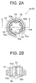
- FIG. 2A is a plane view of the hub member shown in FIG. 1
- FIG. 2B is a sectional view taken along the line B-B in FIG. 2A
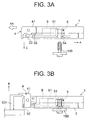
- FIG. 3A is a side view showing a relation between the position of a cassette tape and the position of the rotative driving spindle when the cassette tape in FIG. 1 is set in a driving device
- FIG. 3B is a side view showing such a state that the cassette tape is set in the driving device
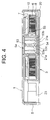
- FIG. 4 is a sectional view of the tape cassette in FIG. 1 in the sliding direction
- FIG. 5A is a plane view showing the rotative driving spindle of the driving device in FIG. 3A
- FIG. 5B is a side view thereof
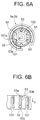
- FIG. 6A is a plane view showing such a state that the rotative driving spindle in FIG. 4 engages the hub member in FIG. 2A
- FIG. 6B is
- the tape cassette 1 for DAT is provided with an upper case 10, a lower case 20 having the insertion holes 21a and 21b for the rotative driving spindle 100 (FIG. 3A) of a driving device, a front cover 4 provided in a front face of the upper case 10 so as to be rotatable at a side shoulder 41, and the slider 3 having two (2) circular openings 31a and 31b, provided so as to be slidable on a face of the lower case 20.
- a couple of the hub members 5a and 5b are stored so as to be rotatable, in which the tape 6 may be wound as a tape-like member around the reel thereof.
- the through holes 51a and 51b are formed, into which the rotative driving spindle 100 (FIG. 3A) is inserted.
- the window member 11 is furnished.
- the upper and the lower sheet 7 and 8 are arranged so as to pinch the hub members 5a and 5b to stabilize a running of the tape 6.
- the tape 6 is, for instance, drawn from the hub member 5b and fed out of the case body through one of the tape pulling out opening 22, and wound around the hub member 5a through the another opening 22. While the tape cassette 1 is not used, the tape 6 placed out of the body case is protected with the slider 3 and the front cover 4.
- the hub brake 9 is provided in the case body for prevention from a contraction of the tape 6, the braking pawl 91 is furnished to lock the hub members 5a and 5b by engagement with the teeth part 51 (FIG. 2A) thereof when the cassette is not used, and the release part 92 is furnished to release the lock when the tape cassette is used.
- the slider 3 covering the lower case 20 closes the hollow part 23 in a close position, which is formed in the case body for tape-loading, and opens the hollow part 23 by sliding toward the direction A.
- the openings 31a and 31b come to match the insertion holes 21a and 21b, respectively, and it makes possible to insert the rotative driving spindle 100 (FIG. 3A) the through hole 52, 52 of the hub members 5a and 5b from the device.
- the hub members 5a and 5b are composed of an outer drum 55 where the tape 6 is wound around, a through hole 52 into which the driving spindle 100 (FIG. 3A) of the driving device is inserted through the opening 54 at the lower face, and the teeth part 51 which engage the brake pawls 91 of the hub brake 9 formed on the upper face.
- the tape is fixed to the groove 55a of the outer drum 55 at the end thereof by pinching with a clamp part (not shown).
- a plurality of (six pieces in FIG.2A) spline projections 53 are arranged equally in the circumferential direction, and widen toward the lower face (side of insertion opening 54) of the hub members 5a and 5b. This is, as illustrated in FIG. 2B, the width at the root of each the spline projection 53 is lineally increased from the upper face to the lower face so that the narrow width m at the upper face comes to the wider width at the lower face (side of insertion opening 54).
- the spline projections 53 are formed so that the side faces 53a and 53b are projected aslant from the root thereof and the top position 53c is flat.
- the side faces 53a and 53b are slanted so as to widen in the axis direction toward the insertion opening 54.
- the tape cassette 1 is inserted into the driving device from the side of the front cover 4 in a direction AA as shown in FIG. 3A.
- the slider 3 is moved rearward (in a direction A), and the under face of the hollow 23 for tape-loading is thereby opened.
- the openings 31a and 31b come to match with the insertion holes 21a and 21b of the lower case 20, respectively, and the hub members 5a and 5b come to be feasible for engagement with the driving spindle 100 of the driving device.
- the tape cassette 1 is moved in the direction C to the under portion of FIG.
- the rotative driving spindle 100 of the driving device in FIG. 3A is formed cylindrically, and three (3) engagement projections 101 elongated in axial direction are provided on the circumferential face thereof.
- Each engagement projection 101 is equally arranged in the circumferential direction, is projected to a radius direction to form side faces 101a, 101b to have same width in an axial direction.
- the hub members 5a and 5b are made possible to rotate by releasing an engagement with the hub brake 9, and the rotative driving spindle 100 is coincidentally inserted into the through hole 52 of hub members 5a, 5b.
- FIG. 6A and 6B when the rotative driving spindle 100 is rotated to the direction R with the driving device, then each engagement projection 101 of the rotative driving spindle 100 engages every other spline projection 53, and the side face 101a of the engagement projection 101 is contacted with the side face 53a of the spline projections 53 at the through hole 52 of the hub members 5a and 5b.
- the width of the engagement projection 101 of the rotative driving spindle 100 is same in an axial direction, and the spline projection 53 widens toward the insertion opening 54 at the side face 53a, the side face 101a of the engagement projection 101 contacts with the side face 53a of the spline projection 53 at the lower end, accordingly.
- the side face 53a slanted so as to widen toward the lower end is forced in the direction D from the side face 101 of the engagement projection 101a, the force toward the insertion opening 54 in the direction D in FIG. 6B is exerted on the hub members 5a, 5b.
- the force is exerted on the hub members 5a, 5b with following the rotation thereof, so that the hub members 5a, 5b are attracted to the lower portion of the figure, thereby being moved to the side of the insertion opening 54.
- the hub members can rotate firmly without vertical movement at the position where they are moved to.
- tape running at the hub members 5a and 5b is stabilized, and it can be prevented from an error occurred during recording or reproducing.
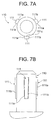
- FIG. 7A is a plane view showing the rotative driving spindle of the driving device in the embodiment
- FIG. 7B is the side view thereof
- FIG. 8A is a plane view showing such a state that the rotative driving spindle in FIG. 7A engages the hub member in FIG. 3A
- FIG. 8B is a developed side view thereof.
- a rotative driving spindle 110 of the driving device in FIG. 3A is formed cylindrically, and on the circumferential face thereof, three (3) engagement projections 111 are formed in axial direction and arranged equally in the circumferential direction, and are projected to the radius direction to form the side faces 111a and 111b.
- Each engagement projection 111 is, for making a form to match the spline projection 53 in FIG.
- the side face 111a of the engagement projection 111 in which the width of upper portion is more than that of lower portion, entirely engages and contacts with the side face 53a of the spline projection 53 of the hub members 5a and 5b.
- the side face 53a slanted to widen toward the lower end is forced by the side face 111a of the engagement projection 111 to the direction D at the wider area than that in FIG. 6A. Therefore, the force toward the insertion opening 54 shown as direction D in FIG. 6B is exerted more strictly on the hub members 5a and 5b.
- the force is applied to the hub members 5a and 5b, so that the hub members are attracted to the lower portion with following the rotation thereof, to thereby be moved to the lower portion, and can rotate stably at the moved portion.
- a tape running with the hub members 5a and 5b is stabilized more, and it may be prevented from an error occurring during recording and reproducing.
- the hub members of the tape cassette 1 set in the driving device are strictly positioned at the lower case 20, and the hub members are not moved vertically during tape running, more stable running may be obtained, accordingly.
- the rotative driving spindle of the driving device may be of FIGS. 5A and 5B.
- the rotative driving spindle 110 does not interfere with the through hole 52 when a cassette tape is set into or taken out from the driving device.
- FIG. 9A is a plane view of the hub member according to the modification
- FIG. 9B is a sectional view taken along the line BB-BB in FIG. 9A
- FIG. 10A is a plane view showing the rotative driving spindle of the driving device according to the modification
- FIG. 10B is a side view thereof
- FIG. 11A is a plane view showing such a state that the rotative driving spindle engages the hub
- FIG. 11B is a developed side view thereof.
- a tapered portion 56 is formed at the lower face of the hub member in the spline projection 53 in the through hole 52 of the hub members 5a and 5b.
- the wide portion 102 is formed at the lower face in an axial direction so as to match with the form of the tapered portion 56 of the spline projection 53.
- the vertical rotation position of the hub members 5a, 5b may be set in the vertical position which determined by the positions of the tapered portion 56 and the wide portion 102. In this example, as explained, it becomes possible to rotate the hub members 5a and 5b with an approximate distance from the inner face of the lower case 20.
- a tape cassette is not limited for DDS and DAT, but also for others having a hub member and other than a structure that the hub member is forcibly held down, such as a tape cassette of reel structure having a flange.
- the tape cassette and the combination structure of the tape cassette and the driving device in the present invention it makes possible to stabilize the position of the hub members during a tape running, whereby the tape running may be stabilized, and an error may be prevented from occurring during recording and reproducing.
Landscapes
- Packaging Of Annular Or Rod-Shaped Articles, Wearing Apparel, Cassettes, Or The Like (AREA)
Applications Claiming Priority (2)
| Application Number | Priority Date | Filing Date | Title |
|---|---|---|---|
| JP11121819A JP2000311462A (ja) | 1999-04-28 | 1999-04-28 | テープカセット及びテープカセットと駆動装置との組み合わせ構造 |
| JP12181999 | 1999-04-28 |
Publications (1)
| Publication Number | Publication Date |
|---|---|
| EP1049094A2 true EP1049094A2 (de) | 2000-11-02 |
Family
ID=14820726
Family Applications (1)
| Application Number | Title | Priority Date | Filing Date |
|---|---|---|---|
| EP00109046A Withdrawn EP1049094A2 (de) | 1999-04-28 | 2000-04-28 | Bandkassette und Kombination von Bandkassette und Antriebsvorrichtung |
Country Status (3)
| Country | Link |
|---|---|
| US (1) | US6484957B1 (de) |
| EP (1) | EP1049094A2 (de) |
| JP (1) | JP2000311462A (de) |
Family Cites Families (4)
| Publication number | Priority date | Publication date | Assignee | Title |
|---|---|---|---|---|
| AT298105B (de) * | 1970-04-27 | 1972-04-25 | Philips Nv | Wickeleinrichtung für Aufzeichnungs- und/oder Wiedergabegeräte und Wickelkern |
| JPH03189979A (ja) * | 1989-12-20 | 1991-08-19 | Sony Corp | テープカセット |
| JP2604313B2 (ja) | 1993-07-30 | 1997-04-30 | 日立造船株式会社 | プラスチックの熱分解装置 |
| JPH0973758A (ja) | 1995-09-06 | 1997-03-18 | Kao Corp | テープカセット |
-
1999
- 1999-04-28 JP JP11121819A patent/JP2000311462A/ja not_active Withdrawn
-
2000
- 2000-04-21 US US09/556,914 patent/US6484957B1/en not_active Expired - Fee Related
- 2000-04-28 EP EP00109046A patent/EP1049094A2/de not_active Withdrawn
Also Published As
| Publication number | Publication date |
|---|---|
| US6484957B1 (en) | 2002-11-26 |
| JP2000311462A (ja) | 2000-11-07 |
Similar Documents
| Publication | Publication Date | Title |
|---|---|---|
| US4449676A (en) | Tape cassette having a reel displacement limiting mechanism | |
| JPH0413804Y2 (de) | ||
| JP4424897B2 (ja) | 記録テープカートリッジ | |
| US7350732B2 (en) | Cartridge case and information recording medium | |
| EP1049094A2 (de) | Bandkassette und Kombination von Bandkassette und Antriebsvorrichtung | |
| EP0398671B1 (de) | Von oben geladene Bandkassette für Videokassette | |
| JP2004199808A (ja) | 記録テープカートリッジ | |
| JP2530922Y2 (ja) | 小型テープカセット | |
| JP2822235B2 (ja) | テープカセット | |
| JPS59104774A (ja) | テ−プカセツト | |
| JP3460158B2 (ja) | テープカセット | |
| EP0490610B1 (de) | Bandkassette | |
| JPS6112624Y2 (de) | ||
| US6978958B2 (en) | Recording tape cartridge | |
| JP2526120Y2 (ja) | 小型テープカセット | |
| JP2530963Y2 (ja) | テープカセット | |
| JPS6112630Y2 (de) | ||
| JP3243839B2 (ja) | スプリング部材及びテープカセット | |
| JPS6041015Y2 (ja) | 小型テ−プカセツト | |
| JPS62184653A (ja) | テ−プレコ−ダ− | |
| JP2569008Y2 (ja) | 磁気テープカセット | |
| JPS626615Y2 (de) | ||
| JPH02126413A (ja) | 磁気記録再生装置とそのアダプタカセット | |
| JPH0533370U (ja) | 小型テープカセツト | |
| JPH058782U (ja) | 小型テープカセツト |
Legal Events
| Date | Code | Title | Description |
|---|---|---|---|
| PUAI | Public reference made under article 153(3) epc to a published international application that has entered the european phase |
Free format text: ORIGINAL CODE: 0009012 |
|
| AK | Designated contracting states |
Kind code of ref document: A2 Designated state(s): AT BE CH CY DE DK ES FI FR GB GR IE IT LI LU MC NL PT SE |
|
| AX | Request for extension of the european patent |
Free format text: AL;LT;LV;MK;RO;SI |
|
| STAA | Information on the status of an ep patent application or granted ep patent |
Free format text: STATUS: THE APPLICATION HAS BEEN WITHDRAWN |
|
| 18W | Application withdrawn |
Withdrawal date: 20020429 |