EP1048849A1 - Flüssigkeitshochdruckpumpe - Google Patents
Flüssigkeitshochdruckpumpe Download PDFInfo
- Publication number
- EP1048849A1 EP1048849A1 EP00202790A EP00202790A EP1048849A1 EP 1048849 A1 EP1048849 A1 EP 1048849A1 EP 00202790 A EP00202790 A EP 00202790A EP 00202790 A EP00202790 A EP 00202790A EP 1048849 A1 EP1048849 A1 EP 1048849A1
- Authority
- EP
- European Patent Office
- Prior art keywords
- pump
- membrane
- chamber
- piston
- hydraulic
- Prior art date
- Legal status (The legal status is an assumption and is not a legal conclusion. Google has not performed a legal analysis and makes no representation as to the accuracy of the status listed.)
- Granted
Links
Images


Classifications
-
- F—MECHANICAL ENGINEERING; LIGHTING; HEATING; WEAPONS; BLASTING
- F02—COMBUSTION ENGINES; HOT-GAS OR COMBUSTION-PRODUCT ENGINE PLANTS
- F02M—SUPPLYING COMBUSTION ENGINES IN GENERAL WITH COMBUSTIBLE MIXTURES OR CONSTITUENTS THEREOF
- F02M59/00—Pumps specially adapted for fuel-injection and not provided for in groups F02M39/00 -F02M57/00, e.g. rotary cylinder-block type of pumps
- F02M59/20—Varying fuel delivery in quantity or timing
- F02M59/24—Varying fuel delivery in quantity or timing with constant-length-stroke pistons having variable effective portion of stroke
- F02M59/243—Varying fuel delivery in quantity or timing with constant-length-stroke pistons having variable effective portion of stroke caused by movement of cylinders relative to their pistons
- F02M59/246—Mechanisms therefor
-
- F—MECHANICAL ENGINEERING; LIGHTING; HEATING; WEAPONS; BLASTING
- F02—COMBUSTION ENGINES; HOT-GAS OR COMBUSTION-PRODUCT ENGINE PLANTS
- F02M—SUPPLYING COMBUSTION ENGINES IN GENERAL WITH COMBUSTIBLE MIXTURES OR CONSTITUENTS THEREOF
- F02M59/00—Pumps specially adapted for fuel-injection and not provided for in groups F02M39/00 -F02M57/00, e.g. rotary cylinder-block type of pumps
- F02M59/02—Pumps specially adapted for fuel-injection and not provided for in groups F02M39/00 -F02M57/00, e.g. rotary cylinder-block type of pumps of reciprocating-piston or reciprocating-cylinder type
- F02M59/04—Pumps specially adapted for fuel-injection and not provided for in groups F02M39/00 -F02M57/00, e.g. rotary cylinder-block type of pumps of reciprocating-piston or reciprocating-cylinder type characterised by special arrangement of cylinders with respect to piston-driving shaft, e.g. arranged parallel to that shaft or swash-plate type pumps
-
- F—MECHANICAL ENGINEERING; LIGHTING; HEATING; WEAPONS; BLASTING
- F02—COMBUSTION ENGINES; HOT-GAS OR COMBUSTION-PRODUCT ENGINE PLANTS
- F02M—SUPPLYING COMBUSTION ENGINES IN GENERAL WITH COMBUSTIBLE MIXTURES OR CONSTITUENTS THEREOF
- F02M59/00—Pumps specially adapted for fuel-injection and not provided for in groups F02M39/00 -F02M57/00, e.g. rotary cylinder-block type of pumps
- F02M59/02—Pumps specially adapted for fuel-injection and not provided for in groups F02M39/00 -F02M57/00, e.g. rotary cylinder-block type of pumps of reciprocating-piston or reciprocating-cylinder type
- F02M59/08—Pumps specially adapted for fuel-injection and not provided for in groups F02M39/00 -F02M57/00, e.g. rotary cylinder-block type of pumps of reciprocating-piston or reciprocating-cylinder type characterised by two or more pumping elements with conjoint outlet or several pumping elements feeding one engine cylinder
-
- F—MECHANICAL ENGINEERING; LIGHTING; HEATING; WEAPONS; BLASTING
- F02—COMBUSTION ENGINES; HOT-GAS OR COMBUSTION-PRODUCT ENGINE PLANTS
- F02M—SUPPLYING COMBUSTION ENGINES IN GENERAL WITH COMBUSTIBLE MIXTURES OR CONSTITUENTS THEREOF
- F02M59/00—Pumps specially adapted for fuel-injection and not provided for in groups F02M39/00 -F02M57/00, e.g. rotary cylinder-block type of pumps
- F02M59/02—Pumps specially adapted for fuel-injection and not provided for in groups F02M39/00 -F02M57/00, e.g. rotary cylinder-block type of pumps of reciprocating-piston or reciprocating-cylinder type
- F02M59/10—Pumps specially adapted for fuel-injection and not provided for in groups F02M39/00 -F02M57/00, e.g. rotary cylinder-block type of pumps of reciprocating-piston or reciprocating-cylinder type characterised by the piston-drive
- F02M59/105—Pumps specially adapted for fuel-injection and not provided for in groups F02M39/00 -F02M57/00, e.g. rotary cylinder-block type of pumps of reciprocating-piston or reciprocating-cylinder type characterised by the piston-drive hydraulic drive
-
- F—MECHANICAL ENGINEERING; LIGHTING; HEATING; WEAPONS; BLASTING
- F02—COMBUSTION ENGINES; HOT-GAS OR COMBUSTION-PRODUCT ENGINE PLANTS
- F02M—SUPPLYING COMBUSTION ENGINES IN GENERAL WITH COMBUSTIBLE MIXTURES OR CONSTITUENTS THEREOF
- F02M59/00—Pumps specially adapted for fuel-injection and not provided for in groups F02M39/00 -F02M57/00, e.g. rotary cylinder-block type of pumps
- F02M59/12—Pumps specially adapted for fuel-injection and not provided for in groups F02M39/00 -F02M57/00, e.g. rotary cylinder-block type of pumps having other positive-displacement pumping elements, e.g. rotary
- F02M59/14—Pumps specially adapted for fuel-injection and not provided for in groups F02M39/00 -F02M57/00, e.g. rotary cylinder-block type of pumps having other positive-displacement pumping elements, e.g. rotary of elastic-wall type
-
- F—MECHANICAL ENGINEERING; LIGHTING; HEATING; WEAPONS; BLASTING
- F02—COMBUSTION ENGINES; HOT-GAS OR COMBUSTION-PRODUCT ENGINE PLANTS
- F02M—SUPPLYING COMBUSTION ENGINES IN GENERAL WITH COMBUSTIBLE MIXTURES OR CONSTITUENTS THEREOF
- F02M59/00—Pumps specially adapted for fuel-injection and not provided for in groups F02M39/00 -F02M57/00, e.g. rotary cylinder-block type of pumps
- F02M59/20—Varying fuel delivery in quantity or timing
- F02M59/24—Varying fuel delivery in quantity or timing with constant-length-stroke pistons having variable effective portion of stroke
- F02M59/243—Varying fuel delivery in quantity or timing with constant-length-stroke pistons having variable effective portion of stroke caused by movement of cylinders relative to their pistons
-
- F—MECHANICAL ENGINEERING; LIGHTING; HEATING; WEAPONS; BLASTING
- F04—POSITIVE - DISPLACEMENT MACHINES FOR LIQUIDS; PUMPS FOR LIQUIDS OR ELASTIC FLUIDS
- F04B—POSITIVE-DISPLACEMENT MACHINES FOR LIQUIDS; PUMPS
- F04B1/00—Multi-cylinder machines or pumps characterised by number or arrangement of cylinders
- F04B1/12—Multi-cylinder machines or pumps characterised by number or arrangement of cylinders having cylinder axes coaxial with, or parallel or inclined to, main shaft axis
- F04B1/14—Multi-cylinder machines or pumps characterised by number or arrangement of cylinders having cylinder axes coaxial with, or parallel or inclined to, main shaft axis having stationary cylinders
-
- F—MECHANICAL ENGINEERING; LIGHTING; HEATING; WEAPONS; BLASTING
- F04—POSITIVE - DISPLACEMENT MACHINES FOR LIQUIDS; PUMPS FOR LIQUIDS OR ELASTIC FLUIDS
- F04B—POSITIVE-DISPLACEMENT MACHINES FOR LIQUIDS; PUMPS
- F04B43/00—Machines, pumps, or pumping installations having flexible working members
- F04B43/02—Machines, pumps, or pumping installations having flexible working members having plate-like flexible members, e.g. diaphragms
- F04B43/06—Pumps having fluid drive
- F04B43/067—Pumps having fluid drive the fluid being actuated directly by a piston
-
- F—MECHANICAL ENGINEERING; LIGHTING; HEATING; WEAPONS; BLASTING
- F04—POSITIVE - DISPLACEMENT MACHINES FOR LIQUIDS; PUMPS FOR LIQUIDS OR ELASTIC FLUIDS
- F04B—POSITIVE-DISPLACEMENT MACHINES FOR LIQUIDS; PUMPS
- F04B53/00—Component parts, details or accessories not provided for in, or of interest apart from, groups F04B1/00 - F04B23/00 or F04B39/00 - F04B47/00
- F04B53/14—Pistons, piston-rods or piston-rod connections
- F04B53/142—Intermediate liquid-piston between a driving piston and a driven piston
Definitions
- the present invention relates to a pump capable of pumping and discharge at high pressure virtually any liquid such as: water, petrol, diesel, oils, corrosive chemical liquids and sludge; but more especially for the high pressure supply of fuel injectors for internal combustion engines.
- the membrane is on one side driven by means mechanical (cam, lever or the like) and is on the other subject to the pressure of discharge: as a result, as soon as the pressure becomes high, the membrane deteriorates at the points of application of mechanical forces.
- a first pump which is a hydraulic pump which pumps and sucks in hydraulic fluid which drives reciprocating the moving parts of a second pump, this last suction and pressurizing the liquid to be pumped.
- These moving elements which provide physical separation between the hydraulic fluid and the fluid to pump, while being moved alternately by the hydraulic fluid, are either deformable membranes or free pistons.
- the free pistons have a defect with regard to sealing, a defect which is essential in the case where one must have an absolute seal. If we put place a seal between the free piston and the cylinder in which it moves, it is not not possible to obtain a perfect seal. If we remove the joint: or there is has a very thin film of oil between the friction surfaces and therefore micro-leaks: or there is no oil film and the friction surfaces will heat up. In the particular case of high pressure petrol injection no leaks, too weak as it is, is not admissible and, obviously, any overheating risks cause an explosion.
- the present invention therefore relates to a pumping device in which the moving parts, driven by an alternative pumping movement by the pump hydraulic and ensuring a completely sealed separation between the liquid hydraulic "motor” and the liquid to be pumped are deformable membranes.
- German patent 2,447,741 WANNER describes a diaphragm pump which is mechanically linked to a piston which slides inside a piston of hydraulic pump.
- the disadvantages are the same as for the patent US 4,392,787 cited above.
- the present invention provides a device in which each membrane is free and in which at the end of each cycle a piston, the dead chamber, located downstream of the top dead center of this piston (position maximum compression), in which the liquid is in contact with the diaphragm is placed in communication with the hydraulic fluid reserve: from so that the liquid there is pumped back to this reserve first by the expansion of the liquid, then by the effect of repression by the membrane which is constrained by a spring.
- the present invention relates to a pump making it possible to pump any kind of liquid while giving it a pressure of very high discharge, of the type constituted by the association of two pumps: on the one hand, a hydraulic pump; on the other hand, a second pump whose mobile means, carrying out the suction and delivery of the liquid to be pumped, are flexible membranes driven in an alternating movement in a direction more in the other by the displacement of the hydraulic fluid pumped then re-aspirated by the first pump characterized in that the pistons of the first pump are hollow and crossed by the hydraulic fluid which, during the suction phase crosses a lunula or groove dug in the face of the bias or cam plate: the deformable membranes each constrained by a spring so that that at the end of the compression stroke of each piston, communication is established between the chamber where the hydraulic fluid is discharged against the membrane and the suction chamber, this liquid being, on the one hand, sucked up by the movement of the piston and driven back by the membrane under the action of its spring, this
- the present invention relates to means making it possible to vary the displacement of the first pump and therefore the fuel flow to the injection devices.
- These means are: either the provision of a tilting platform with variable inclination, or the provision of means in the pistons of the hydraulic pump, having for function of short-circuiting all or part of the volume of hydraulic fluid introduced into the bore during the suction phase.
- each hollow piston of the hydraulic pump is provided openings that can be completely or partially obscured by a movable folder, all movable liners being moved together by a control member subject to engine operating conditions.
- the device according to the invention comprises a first pump, designated by the general reference I and a second pump, designated by the general reference II.
- the first pump I is a pump with axial pistons driven by a movement alternating back and forth by a bias plate 1.
- the bias plate 1 is integral with a motor shaft 2 (driven by any means not shown) carried by bearings 3.
- a plurality of hollow pistons 4 take support against the oblique face of the plate 1 each by means of a sliding pad 5, which is pierced in its center with a bore 6.
- Each piston 4 is held by a spring 7 against its stud.
- On the front face 1 is engraved a lunula 8, When the shaft 2 is rotated, the bias plate 1, the studs 5 and the heads spherical pistons 4a 4 struggle in a chamber 9.
- This chamber 9 opens, through a plurality of holes 22, passing through the body 21 of the pump 1, in a reservoir 11.
- This reservoir 11 is constituted by a cylindrical envelope 23 which surrounds the body 21.
- the face of the bias plate 1 oscillates in the chamber 9 so that the pistons 4 are reciprocated back and forth: in the direction which corresponds to the suction, the pistons 4 are moved by their spring 7; in the other direction which corresponds to the pressure delivery, they are pushed back to against the spring 7 by the bias plate 1.
- the hydraulic fluid which is in the chamber 9 penetrates inside the pistons 4 passing through the lunula 8 and the bore 6 of the studs 5.
- each bore 12 in which slides a hollow piston 4 has at its end a non-return valve ; so that all of said pistons 4 cause a flow under pressure (and even under high pressure since it can exceed 1000 bars with this type of pump).
- none of the bores 12 in which slide the pistons 4 does not include a non-return valve.
- a pump I 1 is associated with the pump I immediately downstream of the latter.
- Each bore 2 of pump I, in which a piston 4 slides, corresponds, in pump II, a chamber or bore 13 divided into two parts 13a and 13b by a flexible membrane 24 supported by a spring 15.
- the part 13a communicates directly with the end of the bore 12, while the part 13b is provided with its end opposite to the membrane 24 of a suction valve 16 and a valve discharge 17. All the valves 17 flow in a common pipe 18.
- each spring 15 is supported on the rear face of the membrane 24 by means of a cup 20.
- the shape of the cup 20 is determined so that the support of the cup 20 on the face rear of the membrane 24 does not cause any deterioration thereof.
- the displacement of the membrane 24 in the direction of the arrow f2 has the effect to suck the product to be pumped in the part 13b of the bore 13, through the valve non-return intake 16 and discharge the hydraulic fluid in the part 13a.
- the product to be pumped is alternately sucked in and then discharged by the movement membranes 24, this movement being caused by variations in the volume occupied by the hydraulic fluid in the parts 13a of the bores 13, these volume variations being caused by alternating delivery and hydraulic fluid suction by the pistons 4 of the first pump I.
- Each membrane 24 is subjected, on its two front and rear faces and this of uniformly distributed over the entire surface of the membrane, at the same pressure: on one side the pressure of the engine hydraulic fluid, on the other the pressure of the pumped liquid.
- the membrane therefore undergoes no mechanical effort and therefore cannot tear.
- the pump according to the present invention is therefore a diaphragm pump in which each membrane is, in the delivery phase, an equipression of each side which allows a discharge pressure equal to the pressure that the first pump I.
- the pump according to the present invention can be used, inter alia, to put in pressure liquids having no greasing power.
- it can be used to supply internal combustion engine injectors (car engines) powered by super-fuel and / or LPG liquid as an alternative fuel for example.
- the super fuel is sucked in by the valves 16, discharged under high pressure (over 50 bars) by the valves 17 without the fuel ever coming into contact with components metal to slide against each other.
- engine oil can advantageously be used as hydraulic fluid itself by having chamber 9 communicate directly with the distribution of engine oil, the temperature of this oil being regulated by the appropriate engine components.
- the pump according to the invention can also be used to circulate under presses drilling mud.
- the suction force of the second pump II which is linked to the power of the springs 15, allows a return to the initial position of the membranes 24, due to the communication with the chamber 9.
- Figures 3 to 5 relate to an improvement to the device of Figures 1 and 2 to means by which it will be possible to vary at will the flow rate of the liquid to pump.
- this liquid is gasoline intended to supply an engine
- the first solution consists in making the first pump 1, in the form of a variable flow pump using a bias plate 1 with variable inclination as this is achieved in certain pumps produced by the applicant.
- the device according to this second solution is characterized in that it comprises a double pump such as that described in patent application 96.07043, but in which each piston of the hydraulic pump is provided with means allowing to cancel all or part of the flow pumped by said piston.
- Figures 3 and 4 describe a double pump similar to that of Figures 1 and 2 in which the same elements have the same references.
- each hollow piston 4 is crossed through partly by a pipe 30.
- the pistons 4 are carried by two supports 31 and 32 pierced with orifices in which said pistons slide.
- the holes drilled in the support 31 are designated by the reference 33, while the holes drilled in the support 32 constitute the cylinders 12 mentioned above.
- the thickness of the support 32 is greater than the maximum stroke of the pistons 4.
- the space between the supports 31 and 32 constitutes an annular chamber 35.
- each piston 4 is partially covered by a jacket sliding 34.
- These sliding liners are all connected to a connecting rod control 38 so that it can slide all together between two positions extremes, the first being illustrated in Figure 3, the second being illustrated in figure 4.
- the springs 7 of FIGS. 1 and 2 which have the function of holding the heads of the pistons pressing against their sliding stud 5 are replaced by a pusher 7b which acts on a flange 6 which is supported on the rear of each head of piston 4.
- the pusher 7b is counterfeited by a spring 7a.
- the output flow of the pump It is regulated as a function of the flow fuel that is needed for injection and that excess fuel returns to the tank are reduced to the maximum.
- the fuel flow rate thus obtained is a pulsed flow rate.
- the shirts 34 are in a position such that only 10 % of the maximum flow rate of pump I is delivered in part 13a of volume 13, this means that this pump I does not supply any flow during 90% of the stroke of each piston or that there is flow only on 10% of the stroke of each piston. This has the effect that the flow is a pulsed flow.
- This device can advantageously be constituted in a similar way to a hydraulic accumulator, that is to say constituted by a capacity having a large volume compared to the flow supplied to injectors and kept under constant pressure.
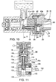
- FIG. 6 represents a pump similar to the pump of FIG. 1, in which the same elements have the same references.
- each volume 13 is divided into two parts 13a, 13b by a membrane 24 pushed back by a spring 15 bearing on the membrane 24 by means of a cup 20.
- the pump of FIG. 6, like that of FIG. 1, comprises a one-piece pump housing 40. in two cylindrical parts 40a, and 40b, the part 40b having an internal diameter greater than that of the part 40a.
- the bearings 3 In the part 40a are arranged the bearings 3, the motor shaft 2, the bias plate 1, the supply chamber 9 and the rear part 4 a of a part 41 in which are drilled the bores 12.
- the front part 41b of this part is located in the part 40b of upper diameter of the casing 40; so that this front part 41b rests against the shoulder which separates the two parts 40a and 40b of the casing 40.
- a circular plate 42 is disposed against said part 41b and is immobilized in position relative thereto by a pin 42a.
- This plate 42 has as many bores 43 that there are bores 12 and chambers 13.
- Chambers 13 are formed in a part 45 which is screwed to the open end of part 40b of the housing 40.
- a membrane 44 which has the form of a disc having the same diameter as the plate 42. The membrane 44 is pinched between the plate 42 of the end of the part 45.
- Each hole 43 communicates with a bore 12 of the pump I and is located opposite a volume 13.
- each chamber 13 is associated with a conduit 50 connected to a chamber 51 where the liquid arrives pump through a pipe 52.
- the pipe 50 is drilled through the mass of the part 45 and opens at its end opposite the chamber 51 against the membrane 44.
- the plate 42 which is interposed between the part 41, in which the bores 12 of the pistons 4 and the part 45, in which the chambers are formed 13 has two housings 53 and 54 connected by a pipe 55.
- the housing 53 is hollowed out in the face of the part 42 which is in contact with the membrane 44; while the housing 54 is hollowed out in the face which is in contact with the part 41.
- the housing 54 has a configuration such that it communicates with the bore 12; and the housing 53 reaches up to the level of the chamber 13.
- the liquid to be pumped (which is for example petrol) arrives by the pipe 52 at a low pressure, of the order of 1 to 2 bars, given by a electric pump of known type, so that as soon as the hydraulic pressure disappears in the housing 53, the membrane 44 is pushed back to release the passage 56.
- each pipe orifice 50 the membrane 44 is provided with a reinforcement cup 57, with a diameter greater than that of the orifice, intended to prevent the membrane from being pushed by the pressure in the orifice of the pipe 50 and thus deteriorated.
- the membrane 44 by deforming between a position where it is at the bottom of the housing 53 and a position where it closes the suction duct 50 plays the role a suction check valve.
- the hydraulic pump I is a swash plate pump or bias plate and the pistons are pistons axial.
- FIG. 11 Such a radial piston pump is shown in FIG. 11.
- This pump has a cam 101, which is an eccentric carried by a shaft motor 102, carried by bearings 103.
- Each piston is a hollow piston 104 restrained by a spring 107, so that its head 104a is in abutment against the cam 101 by means of a sliding stud 105 crossed by an orifice 106.
- Cam 101 struggles in a chamber 109 communicating with a reservoir hydraulic fluid (not shown). Communication between room 109 and the interior of each hollow piston 104 is established when the stud 105 overlaps the groove 108 hollowed out in the cam 101.
- the cam 101 corresponds to the bias plate 1; pistons 104 to pistons 4; the studs 105 to studs 5: the groove 108 at the lunula 8 and the chamber 109 at the chamber 9.
Landscapes
- Engineering & Computer Science (AREA)
- Mechanical Engineering (AREA)
- General Engineering & Computer Science (AREA)
- Chemical & Material Sciences (AREA)
- Combustion & Propulsion (AREA)
- Reciprocating Pumps (AREA)
Applications Claiming Priority (5)
| Application Number | Priority Date | Filing Date | Title |
|---|---|---|---|
| FR9607043A FR2749616B1 (fr) | 1996-06-07 | 1996-06-07 | Pompe a haute pression pour tous liquides |
| FR9607043 | 1996-06-07 | ||
| FR9613502A FR2755472B1 (fr) | 1996-11-06 | 1996-11-06 | Dispositif d'alimentation a haute pression d'injecteurs d'essence pour moteurs a combustion interne |
| FR9613502 | 1996-11-06 | ||
| EP97926060A EP0901575B1 (de) | 1996-06-07 | 1997-05-30 | Hochdruckpumpe für alle flüssigkeiten |
Related Parent Applications (1)
| Application Number | Title | Priority Date | Filing Date |
|---|---|---|---|
| EP97926060A Division EP0901575B1 (de) | 1996-06-07 | 1997-05-30 | Hochdruckpumpe für alle flüssigkeiten |
Publications (2)
| Publication Number | Publication Date |
|---|---|
| EP1048849A1 true EP1048849A1 (de) | 2000-11-02 |
| EP1048849B1 EP1048849B1 (de) | 2005-03-16 |
Family
ID=26232746
Family Applications (2)
| Application Number | Title | Priority Date | Filing Date |
|---|---|---|---|
| EP97926060A Expired - Lifetime EP0901575B1 (de) | 1996-06-07 | 1997-05-30 | Hochdruckpumpe für alle flüssigkeiten |
| EP00202790A Expired - Lifetime EP1048849B1 (de) | 1996-06-07 | 1997-05-30 | Flüssigkeitshochdruckpumpe |
Family Applications Before (1)
| Application Number | Title | Priority Date | Filing Date |
|---|---|---|---|
| EP97926060A Expired - Lifetime EP0901575B1 (de) | 1996-06-07 | 1997-05-30 | Hochdruckpumpe für alle flüssigkeiten |
Country Status (7)
| Country | Link |
|---|---|
| US (1) | US6264437B1 (de) |
| EP (2) | EP0901575B1 (de) |
| JP (1) | JP3990732B2 (de) |
| DE (1) | DE69732802T2 (de) |
| ES (1) | ES2238968T3 (de) |
| PT (1) | PT1048849E (de) |
| WO (1) | WO1997047883A1 (de) |
Cited By (1)
| Publication number | Priority date | Publication date | Assignee | Title |
|---|---|---|---|---|
| FR2883932A1 (fr) * | 2005-04-04 | 2006-10-06 | Siemens Automotive Hydraulics | Perfectionnement aux pompes transfert |
Families Citing this family (25)
| Publication number | Priority date | Publication date | Assignee | Title |
|---|---|---|---|---|
| US6035828A (en) * | 1998-03-11 | 2000-03-14 | Caterpillar Inc. | Hydraulically-actuated system having a variable delivery fixed displacement pump |
| DE59809021D1 (de) * | 1998-05-20 | 2003-08-21 | Wagner Ag Altstaetten J | Membranpumpe zur förderung hochviskoser medien |
| FR2794813B1 (fr) | 1999-06-08 | 2001-09-21 | Peugeot Citroen Automobiles Sa | Pompe a haute pression a bouchon de remplissage perfectionne |
| FR2794811B1 (fr) | 1999-06-08 | 2003-02-07 | Peugeot Citroen Automobiles Sa | Pompe a haute pression a etancheite perfectionnee |
| FR2794812B1 (fr) * | 1999-06-08 | 2003-02-21 | Peugeot Citroen Automobiles Sa | Pompe a haute pression a moyeu perfectionne |
| FR2794810B1 (fr) * | 1999-06-08 | 2001-08-31 | Peugeot Citroen Automobiles Sa | Pompe a haute pression perfectionnee |
| US6561771B2 (en) | 2001-06-19 | 2003-05-13 | Caterpillar Inc | Axial piston pump with center inlet fill |
| JP3719990B2 (ja) * | 2002-02-15 | 2005-11-24 | 株式会社デンソー | 圧縮機 |
| US7125230B2 (en) | 2002-07-09 | 2006-10-24 | Caterpillar Inc | Valve with operation parameter set at assembly and pump using same |
| US6901911B2 (en) | 2002-07-31 | 2005-06-07 | Caterpillar Inc | Pump and hydraulic system with low pressure priming and over pressurization avoidance features |
| AU2003266673A1 (en) * | 2002-10-02 | 2004-04-23 | Bosch Automotive Systems Corpopation | Diesel engine fuel feeder |
| US6802697B2 (en) | 2002-12-30 | 2004-10-12 | Caterpillar Inc | Variable-delivery, fixed-displacement pump |
| DE102004004705A1 (de) * | 2004-01-30 | 2005-08-18 | Robert Bosch Gmbh | Hochdruckpumpe, insbesondere für eine Kraftstoffeinspritzeinrichtung einer Brennkraftmaschine |
| US20060168955A1 (en) * | 2005-02-03 | 2006-08-03 | Schlumberger Technology Corporation | Apparatus for hydraulically energizing down hole mechanical systems |
| US7428812B2 (en) * | 2006-05-04 | 2008-09-30 | Fci Americas Technology, Inc. | Hydraulic tool with wobble plate transmission |
| US7487654B2 (en) * | 2006-10-13 | 2009-02-10 | Fci Americas Technology, Inc. | Hydraulic tool with tactile feedback |
| US8122585B2 (en) * | 2007-02-20 | 2012-02-28 | Hubbell Incorporated | Spanner plate |
| CN102979696B (zh) * | 2012-12-03 | 2015-05-13 | 常州富邦电气有限公司 | 双进气高效气泵 |
| US9909576B2 (en) | 2015-01-23 | 2018-03-06 | Caterpillar Inc. | Pump drive system with hydraulic tappets |
| US20170030341A1 (en) * | 2015-07-27 | 2017-02-02 | Caterpillar Inc. | Multi-plunger cryogenic pump having intake manifold |
| US10024311B2 (en) * | 2015-08-06 | 2018-07-17 | Caterpillar Inc. | Cryogenic pump for liquefied natural gas |
| US9915250B2 (en) * | 2015-08-24 | 2018-03-13 | Caterpillar Inc. | Hydraulic drive system for cryogenic pump |
| US10190556B2 (en) * | 2017-01-09 | 2019-01-29 | Caterpillar Inc. | System and method for lubricating a cryogenic pump |
| DE102018200715A1 (de) * | 2018-01-17 | 2019-07-18 | Robert Bosch Gmbh | Kraftstofffördereinrichtung für kryogene Kraftstoffe |
| DE102018211338A1 (de) * | 2018-07-10 | 2020-01-16 | Robert Bosch Gmbh | Kraftstofffördereinrichtung für kryogene Kraftstoffe und Verfahren zum Betreiben einer Kraftstofffördereinrichtung |
Citations (11)
| Publication number | Priority date | Publication date | Assignee | Title |
|---|---|---|---|---|
| US2301407A (en) * | 1940-06-22 | 1942-11-10 | Dayton Liquid Meter Company | Fuel injection pump |
| US2433222A (en) * | 1945-11-05 | 1947-12-23 | New York Air Brake Co | Pump |
| FR1122769A (fr) * | 1954-04-17 | 1956-09-12 | Pompe d'injection pour moteurs à combustion | |
| FR1211846A (fr) * | 1958-10-18 | 1960-03-18 | Pompe hydraulique pour pulvérisateurs agricoles | |
| US2960936A (en) * | 1958-07-11 | 1960-11-22 | William M Dean | Fuel injection pump |
| FR2119364A5 (de) * | 1970-12-21 | 1972-08-04 | Wagner Josef | |
| FR2164332A5 (de) * | 1971-12-06 | 1973-07-27 | Atlas Copco Ab | |
| DE2447741A1 (de) * | 1973-10-05 | 1975-04-10 | Wanner Engineering | Kolbenvorrichtung fuer eine membranpumpe |
| DE2946529A1 (de) * | 1979-11-17 | 1981-05-27 | Frieseke & Hoepfner Gmbh, 8520 Erlangen | Druckgeregelte mehrzylinder-kolbenpumpe |
| US4392787A (en) * | 1981-01-21 | 1983-07-12 | Wetrok Inc. | Diaphragm pump |
| US4443160A (en) * | 1980-11-13 | 1984-04-17 | Brueninghaus Hydraulik Gmbh | High-pressure piston pump for liquids, preferably for water |
Family Cites Families (16)
| Publication number | Priority date | Publication date | Assignee | Title |
|---|---|---|---|---|
| FR2162332B2 (de) | 1971-12-10 | 1976-10-29 | ||
| JPS4963003A (de) * | 1972-06-16 | 1974-06-19 | ||
| GB1457487A (en) * | 1974-06-19 | 1976-12-01 | Leduc G | Hydraulic swash plate pumps |
| EP0085725B1 (de) * | 1982-02-05 | 1984-11-28 | Bran & Lübbe GmbH | Kolbenmembranpumpe |
| DE3414006C2 (de) * | 1984-04-13 | 1986-03-06 | Bran & Lübbe GmbH, 2000 Norderstedt | Kolbenmembranpumpe |
| US4667638A (en) * | 1984-04-17 | 1987-05-26 | Nippon Soken, Inc. | Fuel injection apparatus for internal combustion engine |
| CA1233363A (en) * | 1984-06-01 | 1988-03-01 | Robert E. Fischell | Single valve diaphragm pump with decreased sensitivity to ambient conditions |
| DE3446914A1 (de) * | 1984-12-21 | 1986-07-03 | Ott Kg Lewa | Membranpumpe mit hydaulisch angetriebener rollmembran |
| ES2022824B3 (es) * | 1987-02-28 | 1991-12-16 | Bran & Luebbe | Bomba de embolo de membrana |
| JPH0223829Y2 (de) * | 1987-05-19 | 1990-06-28 | ||
| US4964345A (en) * | 1987-12-18 | 1990-10-23 | Hydro Rene Leduc | Rail car axle with axial hydraulic pump |
| DE3838141C2 (de) * | 1988-11-10 | 1998-12-24 | Knf Neuberger Gmbh | Membranpumpe |
| DE4141670C2 (de) * | 1991-12-17 | 1994-09-29 | Ott Kg Lewa | Hydraulisch angetriebene Membranpumpe mit Membranhubbegrenzung |
| DE4327970C2 (de) * | 1993-08-19 | 1997-07-03 | Ott Kg Lewa | Hydraulisch angetriebene Membranpumpe mit mechanischer Membranhubbegrenzung |
| FR2721352B1 (fr) * | 1994-06-17 | 1996-09-06 | Leduc Rene Hydro Sa | Pompe à haute pression pour alimenter des injecteurs d'essence pour moteurs à explosion. |
| US5707219A (en) * | 1995-10-04 | 1998-01-13 | Wanner Engineering | Diaphragm pump |
-
1997
- 1997-05-30 DE DE69732802T patent/DE69732802T2/de not_active Expired - Lifetime
- 1997-05-30 ES ES00202790T patent/ES2238968T3/es not_active Expired - Lifetime
- 1997-05-30 WO PCT/FR1997/000943 patent/WO1997047883A1/fr active Application Filing
- 1997-05-30 PT PT00202790T patent/PT1048849E/pt unknown
- 1997-05-30 EP EP97926060A patent/EP0901575B1/de not_active Expired - Lifetime
- 1997-05-30 JP JP50127298A patent/JP3990732B2/ja not_active Expired - Lifetime
- 1997-05-30 US US09/194,437 patent/US6264437B1/en not_active Expired - Lifetime
- 1997-05-30 EP EP00202790A patent/EP1048849B1/de not_active Expired - Lifetime
Patent Citations (11)
| Publication number | Priority date | Publication date | Assignee | Title |
|---|---|---|---|---|
| US2301407A (en) * | 1940-06-22 | 1942-11-10 | Dayton Liquid Meter Company | Fuel injection pump |
| US2433222A (en) * | 1945-11-05 | 1947-12-23 | New York Air Brake Co | Pump |
| FR1122769A (fr) * | 1954-04-17 | 1956-09-12 | Pompe d'injection pour moteurs à combustion | |
| US2960936A (en) * | 1958-07-11 | 1960-11-22 | William M Dean | Fuel injection pump |
| FR1211846A (fr) * | 1958-10-18 | 1960-03-18 | Pompe hydraulique pour pulvérisateurs agricoles | |
| FR2119364A5 (de) * | 1970-12-21 | 1972-08-04 | Wagner Josef | |
| FR2164332A5 (de) * | 1971-12-06 | 1973-07-27 | Atlas Copco Ab | |
| DE2447741A1 (de) * | 1973-10-05 | 1975-04-10 | Wanner Engineering | Kolbenvorrichtung fuer eine membranpumpe |
| DE2946529A1 (de) * | 1979-11-17 | 1981-05-27 | Frieseke & Hoepfner Gmbh, 8520 Erlangen | Druckgeregelte mehrzylinder-kolbenpumpe |
| US4443160A (en) * | 1980-11-13 | 1984-04-17 | Brueninghaus Hydraulik Gmbh | High-pressure piston pump for liquids, preferably for water |
| US4392787A (en) * | 1981-01-21 | 1983-07-12 | Wetrok Inc. | Diaphragm pump |
Cited By (2)
| Publication number | Priority date | Publication date | Assignee | Title |
|---|---|---|---|---|
| FR2883932A1 (fr) * | 2005-04-04 | 2006-10-06 | Siemens Automotive Hydraulics | Perfectionnement aux pompes transfert |
| WO2006106198A1 (fr) * | 2005-04-04 | 2006-10-12 | Siemens Automotive Hydraulics Sa | Perfectionnement aux pompes transfert |
Also Published As
| Publication number | Publication date |
|---|---|
| EP0901575B1 (de) | 2011-06-01 |
| ES2238968T3 (es) | 2005-09-16 |
| US6264437B1 (en) | 2001-07-24 |
| JP3990732B2 (ja) | 2007-10-17 |
| DE69732802T2 (de) | 2006-04-06 |
| PT1048849E (pt) | 2005-05-31 |
| DE69732802D1 (de) | 2005-04-21 |
| EP0901575A1 (de) | 1999-03-17 |
| JP2000511989A (ja) | 2000-09-12 |
| EP1048849B1 (de) | 2005-03-16 |
| WO1997047883A1 (fr) | 1997-12-18 |
Similar Documents
| Publication | Publication Date | Title |
|---|---|---|
| EP1048849B1 (de) | Flüssigkeitshochdruckpumpe | |
| FR2758372A1 (fr) | Compresseur pour systeme de conditionnement d'air d'habitacle de vehicule | |
| FR2654789A1 (fr) | Variateur de vitesse a circuits separes de generation des pressions fonction du couple et du rapport de transmission. | |
| EP0558389B1 (de) | Hydraulische Kolbenpumpe mit Einlassventilen | |
| EP3145745A1 (de) | Fahrzeugmontierte hydraulische unterstützungsvorrichtung und verfahren zum leeren solch einer vorrichtung | |
| FR2825419A1 (fr) | Pompe en particulier pour huile de graissage de moteurs a combustion interne dont le volume transportee est reglable en fonction de la temperature | |
| FR2525697A1 (fr) | Pompe volumetrique a deux etages pour gaz de petrole liquefies en phase liquide, et procede d'injection de carburant pour moteur de vehicule automobile utilisant une telle pompe | |
| FR2889265A1 (fr) | Dispositif d'amplification de pression pour un actionneur hydraulique situe dans un moteur thermique et moteur incorporant un tel dispositif | |
| FR2777954A1 (fr) | Pompe a huile | |
| FR2777944A1 (fr) | Moteur a explosions, a plat et a cylindres opposes | |
| WO2018229368A1 (fr) | Machine de detente et procedes d'utilisation d'une telle machine | |
| EP1999372A1 (de) | Förderpumpe zur hochdruckbenzineinspritzung | |
| EP0731886B1 (de) | Schmiervorrichtung eines zusammenbaus von zwei mechanisch verbundenen teilen, bzw. kolben und pleuelstange | |
| FR2813924A1 (fr) | Dispositif d'alimentation en carburant a haute pression | |
| EP0283348A1 (de) | Hydraulische Pumpen | |
| WO1995012067A1 (fr) | Dispositif d'injection de combustible liquide pour moteur diesel, et moteur diesel comprenant ce dispositif | |
| FR2749616A1 (fr) | Pompe a haute pression pour tous liquides | |
| FR2978207A1 (fr) | Pompe d'agent de refroidissement pour un circuit de refroidissement d'un moteur a combustion interne | |
| FR2598748A1 (fr) | Pompe a injection de carburant liquide. | |
| FR2822199A1 (fr) | Dispositif hydraulique du type pompe a pistons | |
| FR2793848A1 (fr) | Pompe a fluide | |
| CH512672A (fr) | Procédé et dispositif d'injection d'un combustible liquide dans un moteur à combustion interne | |
| EP0180510B1 (de) | Hydraulische Kolbenpumpe mit zwangsläufig angetriebenen Einlassventilen | |
| FR2755472A1 (fr) | Dispositif d'alimentation a haute pression d'injecteurs d'essence pour moteurs a combustion interne | |
| EP0089296A1 (de) | Hydraulische Axialkolbenpumpe mit Schrägscheibe und einer Einrichtung zum Selbstansaugen |
Legal Events
| Date | Code | Title | Description |
|---|---|---|---|
| PUAI | Public reference made under article 153(3) epc to a published international application that has entered the european phase |
Free format text: ORIGINAL CODE: 0009012 |
|
| AC | Divisional application: reference to earlier application |
Ref document number: 901575 Country of ref document: EP |
|
| AK | Designated contracting states |
Kind code of ref document: A1 Designated state(s): DE ES FR GB IT PT SE |
|
| 17P | Request for examination filed |
Effective date: 20000930 |
|
| AKX | Designation fees paid |
Free format text: DE ES FR GB IT PT SE |
|
| GRAP | Despatch of communication of intention to grant a patent |
Free format text: ORIGINAL CODE: EPIDOSNIGR1 |
|
| GRAS | Grant fee paid |
Free format text: ORIGINAL CODE: EPIDOSNIGR3 |
|
| GRAA | (expected) grant |
Free format text: ORIGINAL CODE: 0009210 |
|
| RAP1 | Party data changed (applicant data changed or rights of an application transferred) |
Owner name: HYDRO LEDUC |
|
| AC | Divisional application: reference to earlier application |
Ref document number: 0901575 Country of ref document: EP Kind code of ref document: P |
|
| AK | Designated contracting states |
Kind code of ref document: B1 Designated state(s): DE ES FR GB IT PT SE |
|
| REG | Reference to a national code |
Ref country code: GB Ref legal event code: FG4D Free format text: NOT ENGLISH |
|
| REF | Corresponds to: |
Ref document number: 69732802 Country of ref document: DE Date of ref document: 20050421 Kind code of ref document: P |
|
| GBT | Gb: translation of ep patent filed (gb section 77(6)(a)/1977) |
Effective date: 20050420 |
|
| REG | Reference to a national code |
Ref country code: PT Ref legal event code: SC4A Free format text: AVAILABILITY OF NATIONAL TRANSLATION Effective date: 20050329 |
|
| REG | Reference to a national code |
Ref country code: SE Ref legal event code: TRGR |
|
| REG | Reference to a national code |
Ref country code: ES Ref legal event code: FG2A Ref document number: 2238968 Country of ref document: ES Kind code of ref document: T3 |
|
| PLBE | No opposition filed within time limit |
Free format text: ORIGINAL CODE: 0009261 |
|
| STAA | Information on the status of an ep patent application or granted ep patent |
Free format text: STATUS: NO OPPOSITION FILED WITHIN TIME LIMIT |
|
| 26N | No opposition filed |
Effective date: 20051219 |
|
| PGFP | Annual fee paid to national office [announced via postgrant information from national office to epo] |
Ref country code: PT Payment date: 20060426 Year of fee payment: 10 |
|
| PGFP | Annual fee paid to national office [announced via postgrant information from national office to epo] |
Ref country code: SE Payment date: 20060518 Year of fee payment: 10 |
|
| REG | Reference to a national code |
Ref country code: PT Ref legal event code: MM4A Free format text: LAPSE DUE TO NON-PAYMENT OF FEES Effective date: 20071130 |
|
| EUG | Se: european patent has lapsed | ||
| PG25 | Lapsed in a contracting state [announced via postgrant information from national office to epo] |
Ref country code: PT Free format text: LAPSE BECAUSE OF NON-PAYMENT OF DUE FEES Effective date: 20071130 |
|
| PG25 | Lapsed in a contracting state [announced via postgrant information from national office to epo] |
Ref country code: SE Free format text: LAPSE BECAUSE OF NON-PAYMENT OF DUE FEES Effective date: 20070531 |
|
| PGFP | Annual fee paid to national office [announced via postgrant information from national office to epo] |
Ref country code: DE Payment date: 20120514 Year of fee payment: 16 |
|
| PGFP | Annual fee paid to national office [announced via postgrant information from national office to epo] |
Ref country code: GB Payment date: 20120521 Year of fee payment: 16 |
|
| PGFP | Annual fee paid to national office [announced via postgrant information from national office to epo] |
Ref country code: IT Payment date: 20120522 Year of fee payment: 16 |
|
| PGFP | Annual fee paid to national office [announced via postgrant information from national office to epo] |
Ref country code: ES Payment date: 20120524 Year of fee payment: 16 |
|
| GBPC | Gb: european patent ceased through non-payment of renewal fee |
Effective date: 20130530 |
|
| PG25 | Lapsed in a contracting state [announced via postgrant information from national office to epo] |
Ref country code: DE Free format text: LAPSE BECAUSE OF NON-PAYMENT OF DUE FEES Effective date: 20131203 |
|
| REG | Reference to a national code |
Ref country code: DE Ref legal event code: R119 Ref document number: 69732802 Country of ref document: DE Effective date: 20131203 |
|
| PG25 | Lapsed in a contracting state [announced via postgrant information from national office to epo] |
Ref country code: IT Free format text: LAPSE BECAUSE OF NON-PAYMENT OF DUE FEES Effective date: 20130530 |
|
| PG25 | Lapsed in a contracting state [announced via postgrant information from national office to epo] |
Ref country code: GB Free format text: LAPSE BECAUSE OF NON-PAYMENT OF DUE FEES Effective date: 20130530 |
|
| REG | Reference to a national code |
Ref country code: ES Ref legal event code: FD2A Effective date: 20140606 |
|
| PG25 | Lapsed in a contracting state [announced via postgrant information from national office to epo] |
Ref country code: ES Free format text: LAPSE BECAUSE OF NON-PAYMENT OF DUE FEES Effective date: 20130531 |
|
| REG | Reference to a national code |
Ref country code: FR Ref legal event code: PLFP Year of fee payment: 20 |
|
| PGFP | Annual fee paid to national office [announced via postgrant information from national office to epo] |
Ref country code: FR Payment date: 20160527 Year of fee payment: 20 |