EP1048568A1 - Verfahren und Vorrichtung zum Prüfen von Zigaretten - Google Patents
Verfahren und Vorrichtung zum Prüfen von Zigaretten Download PDFInfo
- Publication number
- EP1048568A1 EP1048568A1 EP00104767A EP00104767A EP1048568A1 EP 1048568 A1 EP1048568 A1 EP 1048568A1 EP 00104767 A EP00104767 A EP 00104767A EP 00104767 A EP00104767 A EP 00104767A EP 1048568 A1 EP1048568 A1 EP 1048568A1
- Authority
- EP
- European Patent Office
- Prior art keywords
- plunger
- cigarette
- coil
- cigarettes
- hall element
- Prior art date
- Legal status (The legal status is an assumption and is not a legal conclusion. Google has not performed a legal analysis and makes no representation as to the accuracy of the status listed.)
- Granted
Links
- 235000019504 cigarettes Nutrition 0.000 title claims abstract description 99
- 238000000034 method Methods 0.000 title claims description 12
- 238000012360 testing method Methods 0.000 claims abstract description 44
- 230000005291 magnetic effect Effects 0.000 claims abstract description 27
- 230000005672 electromagnetic field Effects 0.000 claims abstract description 5
- 230000015572 biosynthetic process Effects 0.000 claims description 24
- 238000011156 evaluation Methods 0.000 claims description 18
- 230000005293 ferrimagnetic effect Effects 0.000 claims description 16
- 238000004806 packaging method and process Methods 0.000 claims description 12
- 230000005294 ferromagnetic effect Effects 0.000 claims description 11
- 238000004519 manufacturing process Methods 0.000 claims description 7
- 230000035515 penetration Effects 0.000 claims description 6
- 238000006424 Flood reaction Methods 0.000 claims description 2
- 238000013016 damping Methods 0.000 claims description 2
- 238000007654 immersion Methods 0.000 claims description 2
- 230000008569 process Effects 0.000 claims description 2
- 230000009897 systematic effect Effects 0.000 claims description 2
- 230000010355 oscillation Effects 0.000 claims 1
- 230000001419 dependent effect Effects 0.000 abstract 1
- 238000006073 displacement reaction Methods 0.000 abstract 1
- 238000005755 formation reaction Methods 0.000 description 20
- ATJFFYVFTNAWJD-UHFFFAOYSA-N Tin Chemical compound [Sn] ATJFFYVFTNAWJD-UHFFFAOYSA-N 0.000 description 6
- 230000008901 benefit Effects 0.000 description 5
- 230000008859 change Effects 0.000 description 5
- 238000013461 design Methods 0.000 description 4
- 230000007257 malfunction Effects 0.000 description 3
- 238000012858 packaging process Methods 0.000 description 3
- 238000010998 test method Methods 0.000 description 3
- 230000004888 barrier function Effects 0.000 description 2
- 238000004140 cleaning Methods 0.000 description 2
- 239000004020 conductor Substances 0.000 description 2
- 230000002950 deficient Effects 0.000 description 2
- 238000005553 drilling Methods 0.000 description 2
- 239000000428 dust Substances 0.000 description 2
- 238000004049 embossing Methods 0.000 description 2
- 238000007373 indentation Methods 0.000 description 2
- 239000000463 material Substances 0.000 description 2
- 230000003287 optical effect Effects 0.000 description 2
- 239000003990 capacitor Substances 0.000 description 1
- 239000000969 carrier Substances 0.000 description 1
- 210000003746 feather Anatomy 0.000 description 1
- 239000002902 ferrimagnetic material Substances 0.000 description 1
- 239000011888 foil Substances 0.000 description 1
- 239000003999 initiator Substances 0.000 description 1
- 238000003780 insertion Methods 0.000 description 1
- 230000037431 insertion Effects 0.000 description 1
- 238000012423 maintenance Methods 0.000 description 1
- 238000005259 measurement Methods 0.000 description 1
- 238000012856 packing Methods 0.000 description 1
- 238000012549 training Methods 0.000 description 1
- 230000032258 transport Effects 0.000 description 1
Images



Classifications
-
- B—PERFORMING OPERATIONS; TRANSPORTING
- B65—CONVEYING; PACKING; STORING; HANDLING THIN OR FILAMENTARY MATERIAL
- B65B—MACHINES, APPARATUS OR DEVICES FOR, OR METHODS OF, PACKAGING ARTICLES OR MATERIALS; UNPACKING
- B65B19/00—Packaging rod-shaped or tubular articles susceptible to damage by abrasion or pressure, e.g. cigarettes, cigars, macaroni, spaghetti, drinking straws or welding electrodes
- B65B19/28—Control devices for cigarette or cigar packaging machines
- B65B19/30—Control devices for cigarette or cigar packaging machines responsive to presence of faulty articles, e.g. incorrectly filled cigarettes
-
- B—PERFORMING OPERATIONS; TRANSPORTING
- B65—CONVEYING; PACKING; STORING; HANDLING THIN OR FILAMENTARY MATERIAL
- B65B—MACHINES, APPARATUS OR DEVICES FOR, OR METHODS OF, PACKAGING ARTICLES OR MATERIALS; UNPACKING
- B65B19/00—Packaging rod-shaped or tubular articles susceptible to damage by abrasion or pressure, e.g. cigarettes, cigars, macaroni, spaghetti, drinking straws or welding electrodes
- B65B19/28—Control devices for cigarette or cigar packaging machines
- B65B19/32—Control devices for cigarette or cigar packaging machines responsive to incorrect grouping of articles or to incorrect filling of packages
Definitions
- the invention relates to a method for testing cigarettes when making or packaging the cigarettes, using a pestle is axially displaced towards a cigarette end, so that if the plunger is incorrectly formed or there is no cigarette occupies a position deviating from an ideal position.
- the invention further relates to a device for testing Cigarettes for cigarette packaging and manufacturing machines with at least one axially slidably mounted Tappet holding a head for immersion in a cigarette end having.
- the invention is therefore based on the problem of testing Improve cigarettes, especially less prone to failure to design.
- the method according to the invention is to solve this problem characterized in that depending on the position of the Tappet an electrical, magnetic assigned to a sensor or electromagnetic field is affected, wherein from the influencing a signal corresponding to the plunger position is produced. Furthermore, the problem is solved by a testing device according to the invention, characterized in that is that the plunger has an area for influencing a electrical, magnetic or associated with a sensor electromagnetic field, the sensor being designed in this way is that, based on the influence of the leg, it corresponds to the position of the plunger Signal generated.
- An advantage of the invention lies in that the test method according to the invention or the inventive Test device is no longer susceptible to dust because it is not based on an optical principle.
- the position of the ram is preferred based on an indentation depth a ferro- and / or ferrimagnetic area of the plunger into the interior of a sensor, in particular annular, coil determined.
- the coil is electrical connected to a measuring device which has a signal depending the penetration depth of the plunger position releases ferromagnetic and / or ferrimagnetic region into the coil.
- the position of the ram is preferred based on the flow of a Hall element forming the sensor of one of magnetic field generated in a magnetic region of the plunger, the Hall element on two opposite sides supplied with an electrical voltage and the signal the plunger position depending on the flooding of the Hall element representing magnetic field is generated.
- the Hall element is preferably an electrical one Connected measuring device that a signal depending on the flooding the Hall element, representing the plunger position Magnetic field emits.
- the advantage of these preferred solutions is that their Size is small enough to accommodate a larger cigarette formation to be able to scan at the same time. Thanks to the invention must now the testing of cigarettes is no longer staggered be performed.
- the devices according to the invention can namely be realized so small that the required Measuring devices, namely Hall elements or coils no larger than the thickness of a cigarette. In particular the coils therefore have an outer diameter that is smaller than a cigarette diameter.
- the plungers are preferably queried individually. This is everyone Ram a single element to be queried, namely a Hall element or a coil, in particular an annular coil.
- the signals emitted by these elements are transmitted by means of a Evaluation unit evaluated. Due to the small design, it can already this evaluation unit housed in the housing of the test device be, so that advantageously a complex Wiring of all individual elements to a central machine control can be omitted.
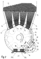
- FIG. 1 shows a cigarette packaging machine 10 with a Cigarette magazine 11, in which cigarettes 12 are located downwards during the ongoing packaging process Move in the direction of arrow 13 shown in FIG. 2.
- the Magazine 11 opens into several, namely four, shown in Fig. 2 Shaft groups 14, each consisting of a plurality, namely seven, shafts 15 exist.
- any cigarette formation 16 consists of three layers, the outer layers each consist of seven and the inner layer of six cigarettes. However, there are other formations with another Number of layers and / or cigarettes per layer possible.
- On rotating cigarette turret 17 transports the cigarette formations 16 for the further packaging process. While the rotation of the formations 16 are in the turret 17 the cigarettes are at rest relative to each other. Therefore, the cigarette turret is preferably suitable for carrying out a cigarette check, especially the completeness check of cigarette formations.
- Fig. 1 are to the right and left of Cigarette turret 17 four testers 18. These testers 18 are on both sides of the cigarette revolver 17 arranged that two devices for checking the filter-side cigarette ends and two other devices 18 serve to check the tobacco-side cigarette ends.
- the Test devices 18 are in one in the longitudinal direction of the cigarette slidable housing 19 housed. The respective housing 19 are shown in the direction of FIGS. 1, 3 and 5 Double arrow 20 slidably by means of a not shown Adjustment device. To perform a test the adjusting device moves a test device 18 in the direction of a cigarette formation 16 to follow one perform the test procedure described in more detail.
- a conveyor 21 leads through the cigarette turret 17 the formations 16 in the direction of arrows 22 in the direction an assembly 23 for wrapping the formations in tinfoil paper.
- Stanniolbobinen 24 store the web-wound Tinfoil paper and give it in the direction of arrows 25, namely in the direction of the assembly 23.
- the tin foil passes an embossing device 26.
- the assembly 23 also serves to cut the tin foil in Cuts that are wrapped around cigarette formations.
- Collar bobbins 27 stock webs of material for collars to be cut, which are covered with tinfoil Cigarette formations 16 are placed.
- FIG. 2 shows a section along the line II-II according to FIG. 1 by the packaging machine 10 for a more detailed illustration the arrangement of the testers 18.
- Two pulled out Test devices 18 shown are on the front of the cigarette revolver 17 and are on a common Carrier 28 mounted.
- Two further test devices 18 are located themselves on the back of the cigarette revolver 17 and are dashed shown. Also these test devices on the back 18 are on a common carrier (not shown) assembled.
- the test devices 18 are each via connections 29 and connection cable 30 with a machine control, not shown connected.
- FIG. 3 and 4 show a test device with annular coils 32, which have a cavity 33 on the inside.
- Cavity 33 can be a ferromagnetic or ferrimagnetic region 34 of a plunger 35 (in the manner of a coil core).
- the plunger 35 is axially displaceable in the housing 19 stored against a spring force. This causes one on an inner wall of the housing 36 supported spring 37 that the plunger 35 from the housing is pushed out until a stop 38, against which the spring 37 presses, a housing outer wall 39 reached.
- the housing is used to carry out a test 19 together with plunger 35 and coils 32 in the direction of to be tested Cigarettes 40, 41, 42 moved.
- the second position is generally characterized in that the ferro / ferrimagnetic area does not completely cover the inside of the coil achieved, for example, even if the ferromagnetic / ferrimagnetic Area 34 the coil interior or the cavity 33 only partially completed.
- the coil 32 By penetration of the ferro / ferrimagnetic area 34 of the plunger 35 in the cavity 34 of the coil 32 becomes the inductance the coil 32 changed.
- This change can be measured to capture.
- the coil to do this with alternating current or alternating voltage.
- the electrical behavior of the coil changes.
- the change in impedance can also be obtained by determining a changed resonance frequency one from this coil and a capacitor formed resonant circuit, or if the Vibration of the resonant circuit breaks off.
- the coil is supplied with DC voltage or applied to direct current.
- the insertion of the ferro- / ferrimagnetic Area then also leads to a change in inductance. This changes with a constant coil current the energy content of the coil.
- Such changes can be recorded by measurement, so that information about the plunger movement and thus the depth of penetration of the plunger can be placed in the cigarette end.
- the plunger 35 is mounted such that the Ferro- and / or ferrimagnetic region 34 of the plunger 35 concentrically can penetrate into the inside of the coil 32.
- the sensor having the coils 32 so small to make it smaller than an approximately 5.3 to 7.9 mm is the cigarette diameter.
- the coils 32 are also arranged at a distance corresponding to this diameter. Therefore, the coils 32 have a smaller outer diameter than the cigarette diameter, preferably maximum 5 mm.
- the plungers 35 then preferably have one maximum outer diameter of about 2 mm.
- the structure described has the advantage that all coils or sensors can be accommodated within the housing 19. Due to the space-saving design, it can also be used inside of the housing 19, which may have a microprocessor Evaluation device are housed, the evaluation board 46 along with electrical and electronic components 47 having. This makes it possible to close the evaluation device to accommodate the actual sensors or coils, so that elaborate wiring of all sensors with one removed lying evaluation unit, e.g. the machine control can be omitted.
- the connection to the machine control 29 must therefore only a few lines, but not one of the number of Sensors have a corresponding number of lines. Thereby the packaging machine is less prone to malfunction overall and moreover, it can be manufactured more cost-effectively.
- the coils 32 are in a carrier element connected to the housing 19 48 arranged, the holes for receiving the annular Coils 32 and bores arranged concentrically thereto for receiving the plunger 35.
- the carrier element 48 also serves the mechanical stability of the arrangement of the coils 32.
- the circuit board 49 is connected to the evaluation circuit board via a plug connection 50 46 connected.
- the circuit board 49 has bores 51, which are opposite the plungers 35 and damage to the Board 49 if the plunger 35 is pressed too deeply into the interior avoid the housing 19.
- FIGS. 5 and 6 Another test device 18 is shown in FIGS. 5 and 6.
- This test device 18 differs from that 3 and 4 in that instead of ferro / ferrimagnetic areas on the tappets on each tappet there is a magnetic area 52.
- This magnetic Area 52 is a bar magnet that creates a constant magnetic field. But it is also a magnetic field generating coils possible.
- By moving one Tappet can now use this magnetic field in a first, namely for the two lower plungers 35 apply a Hall element 53 flood. In a second position, it floods Magnetic field, however, not the Hall element 53 or only less. This second position corresponds to that in FIG. 5 for the upper one Tappet 35 position shown.
- Hall element 53 is on two opposite sides with an electrical Reference voltage or current source connected.
- the measuring device for determining the plunger position with Hall element 53 and magnetic plunger area 52 allow one small design of the device, so that here too the required Electronics can be accommodated within the housing 19 is. Therefore, there is also an evaluation board in this test device 46 for receiving electrical or electronic components 47, in particular a microprocessor for evaluation of the sensor signals or signals of the Hall elements 53, inside of the housing 19 is provided.
- the evaluation board 46 is a Plug connection 50 connected to a circuit board 55.
- This Board 55 has the Hall elements 53, which are in the range of Bores 56 are arranged. These holes 56 are opposite the plungers 35 are arranged and serve to carry out the magnetic Areas 52 of the plunger 35.
- the electrical connection the Hall elements 53 with the evaluation board 46 takes place via printed conductors arranged on the board 55 and via the Plug connection 50.
- a support element connected to the housing 19 57 serves to hold this board 55.
- Both test devices 18 according to FIGS. 3 and 4 or according to FIG. 5 and 6 are via a connecting element 55 with an adjusting device for moving the test device 18 together with the plunger 35 connected to the cigarettes for performing a test.
- This adjustment device is mechanical, electrical, pneumatically and / or hydraulically operated.
- the evaluation unit either already attached to each test device or the machine control system uses the signals supplied by the coils or Hall elements data about possible malfunctions. Because with every test preferably an entire cigarette formation is scanned, For example, three adjacent, each coil or Hall elements indicating an error indicate a blocked cigarette holder. Based on the signals generated by the evaluation unit or machine control an alarm or error signal can be generated or else a control signal to stop the machine or to change it certain machine parameters such as machine speed. Furthermore, a control signal for ejecting a faulty cigarette formation, one Ejector causes the faulty cigarette formation to sort out the packaging process.
- the reduced size of the individual Ram-scanning measuring devices a compact test device, which are not susceptible to interference due to the lack of optical components against dust.
- the invention also allows an evaluation via the operating data acquisition, so that statements about the filling of individual cigarette position possible are. This allows possible unreliability individual cigarette chutes in the cigarette magazine to recognize.
- the cigarette check or head check will advantageously already with one housed in the test device Microprocessor performed so that an evaluation the sensor signals are already possible in the test device.
- the devices explained also have the advantage that a Cleaning the mechanical components without removing the complete Device and electronic components is possible there (not shown) side cover for cleaning can be removed with a compressed air gun, for example. Furthermore, the arrangement described has the advantage that a Tappet 35 pushed in too far does not coils 32 or Hall element 53 and the associated circuit boards 49, 55 can, as is the case with other arrangements with axial arranged initiators or proximity switches occur can. Overall, the invention therefore enables an essential one Improve cigarette testing.
Landscapes
- Engineering & Computer Science (AREA)
- Mechanical Engineering (AREA)
- Manufacturing Of Cigar And Cigarette Tobacco (AREA)
- Wrapping Of Specific Fragile Articles (AREA)
- Measurement Of Length, Angles, Or The Like Using Electric Or Magnetic Means (AREA)
- Transmission And Conversion Of Sensor Element Output (AREA)
- Measuring Instrument Details And Bridges, And Automatic Balancing Devices (AREA)
Abstract
Description
- Fig. 1
- einen Teil einer Zigarettenverpackungsmaschine mit auf beiden Seiten von den zu prüfenden Zigaretten angeordneten Prüfvorrichtungen;
- Fig. 2
- einen Schnitt der Verpackungsmaschine aus Fig. 1 entlang der Linie II-II;
- Fig. 3
- eine Prüfvorrichtung entlang des Schnittes III/V-III/V gemäß Fig. 2;
- Fig. 4
- eine Prüfvorrichtung entlang des Schnittes IV-IV gemäß Fig. 3;
- Fig. 5
- eine Prüfvorrichtung entlang des Schnittes III/V-III/V gemäß Fig. 2;
- Fig. 6
- eine Prüfvorrichtung entlang des Schnitts VI-VI gemäß Fig. 5.
- 10
- Zigarettenverpackungsmaschine
- 11
- Zigarettenmagazin
- 12
- Zigarette
- 13
- Pfeil
- 14
- Schachtgruppe
- 15
- Schacht
- 16
- Zigarettenformation
- 17
- Zigarettenrevolver
- 18
- Prüfvorrichtung
- 19
- Gehäuse
- 20
- Doppelpfeil
- 21
- Förderer
- 22
- Pfeil
- 23
- Baugruppe für Stanniol-Einwicklung
- 24
- Stanniolbobine
- 25
- Pfeil
- 26
- Prägevorrichtung
- 27
- Materialbobine für Kragen
- 28
- Träger
- 29
- Anschluß an Maschinensteuerung
- 30
- Anschlußkabel
- 31a
- Förderstrecke
- 31b
- Förderstrecke
- 32
- ringförmige Spule
- 33
- Hohlraum
- 34
- ferro-/ferrimagnetischer Bereich
- 35
- Stößel
- 36
- Gehäuseinnenwand
- 37
- Feder
- 38
- Anschlag
- 39
- Gehäuseaußenwand
- 40
- Zigarette
- 41
- Zigarette
- 42
- Zigarette
- 43
- Stößelkopf
- 44
- Stößelkopf
- 45
- Stößelkopf
- 46
- Auswerteplatine
- 47
- Bauelement
- 48
- Trägerelement
- 49
- Platine
- 50
- Steckverbindung
- 51
- Bohrung
- 52
- magnetischer Bereich
- 53
- Hall-Element
- 54
- Verbindungselement
- 55
- Platine
- 56
- Bohrung
- 57
- Trägerelement
Claims (12)
- Verfahren zum Prüfen von Zigaretten (12) beim Herstellen oder Verpacken der Zigaretten (12), wobei ein Stößel (35) axial in Richtung eines Zigarettenendes verschoben wird, so daß bei unkorrekter Ausbildung oder Fehlen einer Zigarette (12) der Stößel (35) eine von einer Idealposition abweichende Position einnimmt, dadurch gekennzeichnet, daß in Abhängigkeit der Position des Stößels (35) ein einem Sensor (32, 53) zugeordnetes elektrisches, magnetisches oder elektromagnetisches Feld beeinflußt wird, wobei aus der Beeinflussung ein der Stößelposition entsprechendes Signal erzeugt wird.
- Verfahren nach Anspruch 1, dadurch gekennzeichnet, daß die Position des Stößels (35) anhand einer Eindringtiefe eines ferro- und/oder ferrimagnetischen Bereichs (34) des Stößels (35) in das Innere einer den Sensor bildenden, insbesondere ringförmigen, Spule (32) ermittelt wird.
- Verfahren nach Anspruch 2, dadurch gekennzeichnet, daß in Abhängigkeit der Eindringtiefe ein mit der Spule (32) gebildeter Schwingkreis bedämpft wird, ggfs. bis zum Abreißen der Schwingung.
- Verfahren nach Anspruch 1, dadurch gekennzeichnet, daß die Position des Stößels (35) anhand der Durchflutung eines den Sensor bildenden Hall-Elements (53) von einem von einem magnetischen Bereich (52) des Stößels (35) erzeugten Magnetfeld ermittelt wird, wobei das Hall-Element (53) an zwei gegenüberliegenden Seiten mit einer elektrischen Spannung beaufschlagt und das Signal in Abhängigkeit des das Hall-Element (53) durchflutenden, die Stößelposition repräsentierenden Magnetfelds erzeugt wird.
- Verfahren nach einem der Ansprüche 1 bis 4, dadurch gekennzeichnet, daß während eines Prüfvorgangs eine mehrere Zigaretten (12) aufweisende Zigarettenformation (16) im wesentlichen gleichzeitig geprüft wird, wobei die Stößelpositionen einzeln ausgewertet werden zum Erkennen von systematischen Fehlern, insbesondere von benachbarten, in verschiedenen Lagen liegenden, insbesondere auf einen gestörten Zigarettenschacht hinweisende, Zigarettenpositionen, wobei im Fehlerfall ein Alarm- oder Steuersignal zum Verringern der Drehzahl bzw. zum Anhalten einer Verpackungs- bzw. Herstellungsmaschine (10) erzeugt wird.
- Vorrichtung zum Prüfen von Zigaretten für Zigarettenverpackungs- bzw. -herstellungsmaschinen mit wenigstens einem axial verschiebbar gelagerten Stößel (35), der einen Kopf (43-45) zum Eintauchen in ein Zigarettenende aufweist, dadurch gekennzeichnet, daß der Stößel (35) einen Bereich aufweist zum Beeinflussen eines einem Sensor (32, 53) zugeordneten, elektrischen, magnetischen oder elektromagnetischen Feldes, wobei der Sensor (32, 53) derart ausgebildet ist, daß er anhand der Beeinflussung ein der Stößelposition entsprechendes Signal erzeugt.
- Vorrichtung nach Anspruch 6, dadurch gekennzeichnet, daß der Stößel (35) einen ferro- und/oder ferrimagnetischen Bereich (34) aufweist, der in einer ersten Stößelposition konzentrisch in das Innere einer den Sensor bildenden, insbesondere ringförmigen, Spule (32) eindringt, während in einer zweiten Stößelposition dieser Bereich weniger oder gar nicht in das Spuleninnere (33) eindringt, und eine mit der Spule (32) elektrisch verbundene Meßeinrichtung vorgesehen ist, die ein Signal in Abhängigkeit der die Stößelposition repräsentierenden Eindringtiefe dieses Bereichs (34) in die Spule (32) abgibt.
- Vorrichtung nach Anspruch 6 oder 7, dadurch gekennzeichnet, daß der ferro- und/oder ferrimagnetische Bereich (34) als Dämpfungselement eines mit der Spule (32) gebildeten Schwingkreises wirkt.
- Vorrichtung nach Anspruch 6, dadurch gekennzeichnet, daß der Stößel (35) einen magnetischen Bereich (52) aufweist, dessen Magnetfeld in einer ersten Stößelposition ein den Sensor bildenden Hall-Element (53) durchflutet, während das Magnetfeld in einer zweiten Stößelposition das Hall-Element (53) geringer oder gar nicht durchflutet, und eine mit zwei einander gegenüberliegenden Seiten des Hall-Elements (53) verbundene elektrische Quelle und eine mit zwei weiteren dazu versetzt angeordneten Seiten des Hall-Element (53) verbundene elektrische Meßeinrichtung vorgesehen sind, die ein Signal in Abhängigkeit des das Hall-Element (53) durchflutenden, die Stößelposition repräsentierenden Magnetfelds abgibt.
- Vorrichtung nach einem der Ansprüche 6 bis 9, dadurch gekennzeichnet, daß sie eine der Anzahl von Zigaretten (12) innerhalb einer Zigarettenformation (16), insbesondere 7/6/7-Formation, entsprechende Anzahl von Stößeln (35) und Sensoren (32, 53) aufweist, die derart angeordnet sind, daß jeder Stößel (35) in eine Zigarette der Formation (16) eintauchen kann, und die Sensoren (32, 53) zum Abgeben einer dieser Anzahl entsprechenden Anzahl von einzeln auswertbaren Signalen ausgebildet sind.
- Vorrichtung nach einem der Ansprüche 6 bis 10, dadurch gekennzeichnet, daß sie eine Auswerteeinheit aufweist zum Auswerten des Signals bzw. der Signale und um im Fehlerfall ein Alarm- oder Steuersignal zum Verringern der Drehzahl bzw. zum Anhalten der Verpackungs- bzw. Herstellungsmaschine zu erzeugen.
- Vorrichtung nach einem der Ansprüche 6 bis 11, dadurch gekennzeichnet, daß sie in einem in Richtung der Zigarettenlängsachse verschiebbaren Gehäuse (19) untergebracht ist, das mechanisch mit einer Verstelleinrichtung zum Heranfahren der Stößel an die Zigaretten (12) zum Durchführen eines Prüfvorgangs verbunden ist.
Applications Claiming Priority (2)
| Application Number | Priority Date | Filing Date | Title |
|---|---|---|---|
| DE19919207A DE19919207A1 (de) | 1999-04-28 | 1999-04-28 | Verfahren und Vorrichtung zum Prüfen von Zigaretten |
| DE19919207 | 1999-04-28 |
Publications (2)
| Publication Number | Publication Date |
|---|---|
| EP1048568A1 true EP1048568A1 (de) | 2000-11-02 |
| EP1048568B1 EP1048568B1 (de) | 2004-06-09 |
Family
ID=7906088
Family Applications (1)
| Application Number | Title | Priority Date | Filing Date |
|---|---|---|---|
| EP00104767A Expired - Lifetime EP1048568B1 (de) | 1999-04-28 | 2000-03-04 | Verfahren und Vorrichtung zum Prüfen von Zigaretten |
Country Status (6)
| Country | Link |
|---|---|
| US (1) | US6508138B1 (de) |
| EP (1) | EP1048568B1 (de) |
| JP (1) | JP2000350570A (de) |
| CN (1) | CN1211253C (de) |
| BR (1) | BR0002259A (de) |
| DE (2) | DE19919207A1 (de) |
Cited By (2)
| Publication number | Priority date | Publication date | Assignee | Title |
|---|---|---|---|---|
| EP1419967A1 (de) * | 2002-11-12 | 2004-05-19 | Focke & Co. (GmbH & Co.) | Verfahren und Vorrichtung zum Überprüfen von stabförmigen Gegenständen, insbesondere Zigaretten |
| CN108323797A (zh) * | 2018-02-09 | 2018-07-27 | 杭州安脉盛智能技术有限公司 | 基于gpr模型的烟支重量控制系统启动位置预测方法及系统 |
Families Citing this family (8)
| Publication number | Priority date | Publication date | Assignee | Title |
|---|---|---|---|---|
| ITBO20030470A1 (it) * | 2003-08-01 | 2005-02-02 | Gd Spa | Macchina automatica per il trattamento di articoli e provvista di un dispositivo di rilevamento di posizione con sensori ad effetto di hall. |
| DE102008053593B4 (de) * | 2008-10-16 | 2012-08-23 | Balluff Gmbh | Festanschlagvorrichtung für mindestens einen Näherungssensor und Näherungssensor-Festanschlagvorrichtung-Kombination |
| CN102556453A (zh) * | 2010-12-28 | 2012-07-11 | 江苏大富豪啤酒有限公司 | 一种验盖机 |
| CN102152960B (zh) * | 2011-01-20 | 2013-03-20 | 浙江中烟工业有限责任公司 | 一种卷烟成品入库抽检方法 |
| CN103760610A (zh) * | 2013-12-26 | 2014-04-30 | 中国电子科技集团公司第四十一研究所 | 一种穿入式环形传感器 |
| CN106314854B (zh) * | 2015-07-06 | 2018-10-02 | 中烟机械技术中心有限责任公司 | 能够实现单独推送的机械式推送机构 |
| BR112022007767A2 (pt) * | 2019-12-23 | 2022-07-05 | Philip Morris Products Sa | Método e aparelho para inspecionar um artigo gerador de aerossol indutivamente aquecível quanto à presença de um susceptor e um alinhamento de artigo desejado |
| KR20230091948A (ko) * | 2020-10-21 | 2023-06-23 | 필립모리스 프로덕츠 에스.에이. | 로드 형상 물품의 품질 관리를 위한 검사 디바이스 |
Citations (3)
| Publication number | Priority date | Publication date | Assignee | Title |
|---|---|---|---|---|
| DE499028C (de) * | 1927-04-07 | 1930-07-03 | United Cigarette Mach Co Inc | Vorrichtung zum Entfernen ungenuegend gefuellter Packungen bei Packmaschinen, insbesondere bei Zigarettenpackmaschinen |
| US3874227A (en) * | 1972-06-16 | 1975-04-01 | Heinz Focke | Testing devices for cigarette packing machines |
| GB2196311A (en) * | 1986-10-17 | 1988-04-27 | Gd Spa | Sensing groups of cigarettes on a conveyor |
Family Cites Families (12)
| Publication number | Priority date | Publication date | Assignee | Title |
|---|---|---|---|---|
| FR1122720A (fr) * | 1954-05-24 | 1956-09-12 | Arenco Ab | Dispositif pour détecter les défauts dans des ensembles de cigarettes |
| FR1271375A (fr) * | 1960-10-07 | 1961-09-08 | Molins Machine Co Ltd | Dispositif pour le contrôle de pièces par palpage |
| DE2311084A1 (de) * | 1973-03-06 | 1974-09-26 | Hauni Werke Koerber & Co Kg | Vorrichtung zum pruefen von formationen aus zigaretten |
| GB2044457B (en) * | 1979-03-21 | 1983-11-23 | Molins Ltd | End gauge and hardness gauge |
| IT1201606B (it) * | 1986-12-17 | 1989-02-02 | Gd Spa | Dispositivo di controllo di sigarette in una macchina impacchettatrice |
| FR2633126B1 (fr) * | 1988-06-17 | 1993-11-26 | Aerospatiale Ste Nationale Indle | Procede et systeme pour l'exploitation de signaux provenant de capteurs inductifs lineaires de deplacement |
| DE4015692A1 (de) * | 1990-05-16 | 1991-11-21 | Sikora Industrieelektronik | Vorrichtung zur messung der lage eines leiterstrangs eines kabels im kabelmantel |
| DE4239635C2 (de) * | 1992-11-23 | 1998-02-12 | Hartmann & Braun Ag | Einrichtung zur Wegerfassung von Ventilstangenbewegungen elektropneumatischer Stellungsregler |
| EP0668486A3 (de) * | 1994-02-22 | 1997-07-30 | Heidenhain Gmbh Dr Johannes | Längen- oder Winkelmesseinrichtung. |
| US5801530A (en) * | 1995-04-17 | 1998-09-01 | Namco Controls Corporation | Proximity sensor having a non-ferrous metal shield for enhanced sensing range |
| US5781005A (en) * | 1995-06-07 | 1998-07-14 | Allegro Microsystems, Inc. | Hall-effect ferromagnetic-article-proximity sensor |
| JPH09113203A (ja) * | 1995-10-16 | 1997-05-02 | Toyoda Mach Works Ltd | 差動トランスおよびそれを用いた測定装置 |
-
1999
- 1999-04-28 DE DE19919207A patent/DE19919207A1/de not_active Withdrawn
-
2000
- 2000-03-04 DE DE50006723T patent/DE50006723D1/de not_active Expired - Lifetime
- 2000-03-04 EP EP00104767A patent/EP1048568B1/de not_active Expired - Lifetime
- 2000-04-25 JP JP2000124512A patent/JP2000350570A/ja active Pending
- 2000-04-27 CN CNB00107069XA patent/CN1211253C/zh not_active Expired - Fee Related
- 2000-04-27 BR BR0002259-4A patent/BR0002259A/pt not_active IP Right Cessation
- 2000-04-27 US US09/559,992 patent/US6508138B1/en not_active Expired - Fee Related
Patent Citations (3)
| Publication number | Priority date | Publication date | Assignee | Title |
|---|---|---|---|---|
| DE499028C (de) * | 1927-04-07 | 1930-07-03 | United Cigarette Mach Co Inc | Vorrichtung zum Entfernen ungenuegend gefuellter Packungen bei Packmaschinen, insbesondere bei Zigarettenpackmaschinen |
| US3874227A (en) * | 1972-06-16 | 1975-04-01 | Heinz Focke | Testing devices for cigarette packing machines |
| GB2196311A (en) * | 1986-10-17 | 1988-04-27 | Gd Spa | Sensing groups of cigarettes on a conveyor |
Cited By (3)
| Publication number | Priority date | Publication date | Assignee | Title |
|---|---|---|---|---|
| EP1419967A1 (de) * | 2002-11-12 | 2004-05-19 | Focke & Co. (GmbH & Co.) | Verfahren und Vorrichtung zum Überprüfen von stabförmigen Gegenständen, insbesondere Zigaretten |
| US7021125B2 (en) | 2002-11-12 | 2006-04-04 | Focke & Co. (Gmbh & Co.) | Process and apparatus for checking rod-like articles, in particular cigarettes |
| CN108323797A (zh) * | 2018-02-09 | 2018-07-27 | 杭州安脉盛智能技术有限公司 | 基于gpr模型的烟支重量控制系统启动位置预测方法及系统 |
Also Published As
| Publication number | Publication date |
|---|---|
| US6508138B1 (en) | 2003-01-21 |
| CN1211253C (zh) | 2005-07-20 |
| EP1048568B1 (de) | 2004-06-09 |
| DE19919207A1 (de) | 2000-11-02 |
| DE50006723D1 (de) | 2004-07-15 |
| CN1271677A (zh) | 2000-11-01 |
| BR0002259A (pt) | 2000-11-07 |
| JP2000350570A (ja) | 2000-12-19 |
Similar Documents
| Publication | Publication Date | Title |
|---|---|---|
| EP0470118B1 (de) | Prüfvorrichtung zum prüfen von elektrischen oder elektronischen prüflingen | |
| DE69734815T2 (de) | Fall-nadelbett-prüfgerät für bestückte gedruckte schaltungen | |
| EP1048568B1 (de) | Verfahren und Vorrichtung zum Prüfen von Zigaretten | |
| EP4471435A2 (de) | Prüfnadel, prüfsonde und fingertester zum testen von leiterplatten | |
| EP0224471B1 (de) | Vorrichtung zum Prüfen von Leiterplatten | |
| WO2003015281A2 (de) | Kapazitiver näherungssensor zum erfassen von bauelementgur-ten, bauelemente-zufürvorrichtung und verfahren zum erfassen von bauelementgurten | |
| EP1784071A1 (de) | Vorrichtung zum Vorbereiten einer Mehrschicht- Leiterplatte auf das Bohren von Kontaktierungsbohrungen | |
| EP2040227B1 (de) | Verfahren zum Prüfen von Münzen | |
| DE1930410A1 (de) | Automatisches Pruefgeraet fuer elektrische Schaltungselemente | |
| AT412330B (de) | Handhabungsmodul für wenigstens ein bauteil zum be- und entstücken eines bauteilträgers | |
| DE102019104084B4 (de) | Verfahren zur Beeinflussung der Induktivität und/oder Kapazität einer elektronischen Schaltung | |
| DE3031103A1 (de) | Verfahren zur pruefung des lageversatzes bei mehrlagenleiterplatten | |
| DE102012002884A1 (de) | Verfahren und Vorrichtung zum kontaktlosen Prüfen eines flächigen Sicherheitsdokuments | |
| EP0408490B1 (de) | Verfahren und Vorrichtung zum Zählen von Druckprodukten | |
| DE3638428C1 (en) | Processing device with in-register positioning for offset printing formes | |
| DE102011054105A1 (de) | Verbindungsleiterplatte | |
| DE2343668A1 (de) | Vorrichtung zum pruefen der enden von stabfoermigen tabakartikeln, insbesondere von zigaretten | |
| DE10018198A1 (de) | Sensoreinrichtung und Verfahren zum berührungslosen Abtasten einer Oberfläche eines Gegenstandes | |
| DE19534313C2 (de) | Verfahren zur Erfassung von Position und Versatz von Lagen an Mehrlagenleiterplatten | |
| DE19508213B4 (de) | Fügeüberprüfung | |
| DE10104373B4 (de) | Verfahren zur Funktionskontrolle einer Positionsmesseinrichtung und Positionsmesseinrichtung zur Durchführung des Verfahrens | |
| DE2919836A1 (de) | Fadenbruchdetektor | |
| EP2207148A2 (de) | Induktive Messanordnung für Freifall-Münzgeräte | |
| EP1317674A1 (de) | Verfahren und vorrichtung zur prüfung von leiterplatten auf ihre funktionsfähigkeit | |
| DE102019205812A1 (de) | Fehleridentifikation in einem Fertigungs- oder Bearbeitungsprozess für ein Bauteil, insbesondere für eine Steuerplatine, mit einem Sensor-Trägerteil |
Legal Events
| Date | Code | Title | Description |
|---|---|---|---|
| PUAI | Public reference made under article 153(3) epc to a published international application that has entered the european phase |
Free format text: ORIGINAL CODE: 0009012 |
|
| AK | Designated contracting states |
Kind code of ref document: A1 Designated state(s): CH DE FR GB IT LI NL |
|
| AX | Request for extension of the european patent |
Free format text: AL;LT;LV;MK;RO;SI |
|
| 17P | Request for examination filed |
Effective date: 20010426 |
|
| AKX | Designation fees paid |
Free format text: AT BE CH CY DE DK LI |
|
| RBV | Designated contracting states (corrected) |
Designated state(s): CH DE FR GB IT LI NL |
|
| 17Q | First examination report despatched |
Effective date: 20030530 |
|
| GRAP | Despatch of communication of intention to grant a patent |
Free format text: ORIGINAL CODE: EPIDOSNIGR1 |
|
| GRAS | Grant fee paid |
Free format text: ORIGINAL CODE: EPIDOSNIGR3 |
|
| GRAA | (expected) grant |
Free format text: ORIGINAL CODE: 0009210 |
|
| AK | Designated contracting states |
Kind code of ref document: B1 Designated state(s): CH DE FR GB IT LI NL |
|
| REG | Reference to a national code |
Ref country code: GB Ref legal event code: FG4D Free format text: NOT ENGLISH |
|
| REG | Reference to a national code |
Ref country code: CH Ref legal event code: EP |
|
| REF | Corresponds to: |
Ref document number: 50006723 Country of ref document: DE Date of ref document: 20040715 Kind code of ref document: P |
|
| REG | Reference to a national code |
Ref country code: CH Ref legal event code: NV Representative=s name: R. A. EGLI & CO. PATENTANWAELTE |
|
| GBT | Gb: translation of ep patent filed (gb section 77(6)(a)/1977) |
Effective date: 20040726 |
|
| RAP2 | Party data changed (patent owner data changed or rights of a patent transferred) |
Owner name: FOCKE & CO. (GMBH & CO. KG) |
|
| NLT2 | Nl: modifications (of names), taken from the european patent patent bulletin |
Owner name: FOCKE & CO. (GMBH & CO. KG) |
|
| ET | Fr: translation filed | ||
| PLBE | No opposition filed within time limit |
Free format text: ORIGINAL CODE: 0009261 |
|
| STAA | Information on the status of an ep patent application or granted ep patent |
Free format text: STATUS: NO OPPOSITION FILED WITHIN TIME LIMIT |
|
| 26N | No opposition filed |
Effective date: 20050310 |
|
| PGFP | Annual fee paid to national office [announced via postgrant information from national office to epo] |
Ref country code: CH Payment date: 20090317 Year of fee payment: 10 |
|
| PGFP | Annual fee paid to national office [announced via postgrant information from national office to epo] |
Ref country code: IT Payment date: 20100313 Year of fee payment: 11 |
|
| PGFP | Annual fee paid to national office [announced via postgrant information from national office to epo] |
Ref country code: NL Payment date: 20100304 Year of fee payment: 11 |
|
| REG | Reference to a national code |
Ref country code: CH Ref legal event code: PL |
|
| PG25 | Lapsed in a contracting state [announced via postgrant information from national office to epo] |
Ref country code: LI Free format text: LAPSE BECAUSE OF NON-PAYMENT OF DUE FEES Effective date: 20100331 Ref country code: CH Free format text: LAPSE BECAUSE OF NON-PAYMENT OF DUE FEES Effective date: 20100331 |
|
| PGFP | Annual fee paid to national office [announced via postgrant information from national office to epo] |
Ref country code: FR Payment date: 20110317 Year of fee payment: 12 |
|
| REG | Reference to a national code |
Ref country code: NL Ref legal event code: V1 Effective date: 20111001 |
|
| PG25 | Lapsed in a contracting state [announced via postgrant information from national office to epo] |
Ref country code: NL Free format text: LAPSE BECAUSE OF NON-PAYMENT OF DUE FEES Effective date: 20111001 |
|
| PG25 | Lapsed in a contracting state [announced via postgrant information from national office to epo] |
Ref country code: IT Free format text: LAPSE BECAUSE OF NON-PAYMENT OF DUE FEES Effective date: 20110304 |
|
| REG | Reference to a national code |
Ref country code: FR Ref legal event code: ST Effective date: 20121130 |
|
| PG25 | Lapsed in a contracting state [announced via postgrant information from national office to epo] |
Ref country code: FR Free format text: LAPSE BECAUSE OF NON-PAYMENT OF DUE FEES Effective date: 20120402 |
|
| PGFP | Annual fee paid to national office [announced via postgrant information from national office to epo] |
Ref country code: GB Payment date: 20150304 Year of fee payment: 16 |
|
| PGFP | Annual fee paid to national office [announced via postgrant information from national office to epo] |
Ref country code: DE Payment date: 20150326 Year of fee payment: 16 |
|
| REG | Reference to a national code |
Ref country code: DE Ref legal event code: R119 Ref document number: 50006723 Country of ref document: DE |
|
| GBPC | Gb: european patent ceased through non-payment of renewal fee |
Effective date: 20160304 |
|
| PG25 | Lapsed in a contracting state [announced via postgrant information from national office to epo] |
Ref country code: DE Free format text: LAPSE BECAUSE OF NON-PAYMENT OF DUE FEES Effective date: 20161001 Ref country code: GB Free format text: LAPSE BECAUSE OF NON-PAYMENT OF DUE FEES Effective date: 20160304 |