EP1046888A1 - Dispositif d'affichage et/ou de contrôle pour des fluides - Google Patents
Dispositif d'affichage et/ou de contrôle pour des fluides Download PDFInfo
- Publication number
- EP1046888A1 EP1046888A1 EP99120093A EP99120093A EP1046888A1 EP 1046888 A1 EP1046888 A1 EP 1046888A1 EP 99120093 A EP99120093 A EP 99120093A EP 99120093 A EP99120093 A EP 99120093A EP 1046888 A1 EP1046888 A1 EP 1046888A1
- Authority
- EP
- European Patent Office
- Prior art keywords
- housing
- connection
- parts
- connecting part
- switching device
- Prior art date
- Legal status (The legal status is an assumption and is not a legal conclusion. Google has not performed a legal analysis and makes no representation as to the accuracy of the status listed.)
- Granted
Links
Images


Classifications
-
- G—PHYSICS
- G01—MEASURING; TESTING
- G01F—MEASURING VOLUME, VOLUME FLOW, MASS FLOW OR LIQUID LEVEL; METERING BY VOLUME
- G01F23/00—Indicating or measuring liquid level or level of fluent solid material, e.g. indicating in terms of volume or indicating by means of an alarm
- G01F23/30—Indicating or measuring liquid level or level of fluent solid material, e.g. indicating in terms of volume or indicating by means of an alarm by floats
- G01F23/64—Indicating or measuring liquid level or level of fluent solid material, e.g. indicating in terms of volume or indicating by means of an alarm by floats of the free float type without mechanical transmission elements
- G01F23/72—Indicating or measuring liquid level or level of fluent solid material, e.g. indicating in terms of volume or indicating by means of an alarm by floats of the free float type without mechanical transmission elements using magnetically actuated indicating means
- G01F23/74—Indicating or measuring liquid level or level of fluent solid material, e.g. indicating in terms of volume or indicating by means of an alarm by floats of the free float type without mechanical transmission elements using magnetically actuated indicating means for sensing changes in level only at discrete points
-
- H—ELECTRICITY
- H01—ELECTRIC ELEMENTS
- H01H—ELECTRIC SWITCHES; RELAYS; SELECTORS; EMERGENCY PROTECTIVE DEVICES
- H01H36/00—Switches actuated by change of magnetic field or of electric field, e.g. by change of relative position of magnet and switch, by shielding
- H01H36/0006—Permanent magnet actuating reed switches
- H01H36/0033—Mountings; Housings; Connections
-
- H—ELECTRICITY
- H01—ELECTRIC ELEMENTS
- H01H—ELECTRIC SWITCHES; RELAYS; SELECTORS; EMERGENCY PROTECTIVE DEVICES
- H01H36/00—Switches actuated by change of magnetic field or of electric field, e.g. by change of relative position of magnet and switch, by shielding
- H01H36/02—Switches actuated by change of magnetic field or of electric field, e.g. by change of relative position of magnet and switch, by shielding actuated by movement of a float carrying a magnet
Definitions
- the invention relates to a device for displaying and / or checking of fluids with at least one fluid connection in a housing flows into which a float can be moved depending on the fluid level is guided, which controls an electrical switching device.
- the liquid level by an electrical switching signal is checked.
- the switching device runs transversely to the direction of travel of the Float body and is received directly at the end of the housing.
- the switching device is not covered by parts of the housing directly facing the float and within the fluid arranged.
- the addressed switching signal can be used as a warning or be used for level control.
- the medium in the form of the fluid penetrates into the device through a lower connection hole and lifts in the housing in the form of a riser pipe to a float.
- the Float body now has the level of the medium in the tank to which the device is connected.
- the float body actuates a switch contact of an electrical one Circuit.
- the switching contact can be designed in the manner of a closer, at the Actuation a circuit is closed, or in the manner of an opener, which then breaks the circuit.
- Another variant exists in training the switch contact as a changeover contact, which then as Normally open contact as well as opener can be used.
- the riser pipe is transparent, it can then be used visible float body the respective liquid level of the fluid or visually check the medium.
- the known liquid level indicator can also be equipped with a temperature sensor, so as to monitor the temperature of the fluid.
- a switch contact and part of the switching device usually serves a reed switch, which is in one Cross tube is included, which with its ends reaching through the housing is in contact with it. The tightness is at the transition point between the cross tube and the housing extreme temperature fluctuations are not guaranteed.
- the connecting cables for the reed switch reach through silicone seals at the end of the Cross tube and are with connecting wires in the end connector of the housing can be firmly connected.
- This known solution is expensive in the Construction, so that a high cost-intensive assembly effort becomes necessary. Furthermore, due to the mentioned assembly technology the individual components firmly connected, so that an exchange of components for new ones is correspondingly complex is.
- the object of the invention based on further improving the known devices to the extent that the assembly and repair costs can be kept low that even with extreme temperature fluctuations, the tightness of the device is guaranteed and that with high functional reliability a low Size is reached.
- a device solves one of these tasks the features of claim 1 in its entirety.
- the electrical switching device is part of a housing connectable connecting part, which receives the switching device in such a way that it is guided without contact within the housing is an assembly formed from the switching device, in particular in the form of Reed switch, and the connector that can be connected to the housing.
- the switching device is contact-free via the connecting part guided within the housing so that the connected to the housing known cross tube for receiving the reed switch can be omitted and consequently there are no more sealing problems.
- the number of parts is significantly reduced compared to the known solutions, which lowers the assembly and manufacturing effort. Because the connector is formed in several parts, one of the parts being a receiving space for the switching device is a modular construction of the components reached, the related components easily detachable with each other are connected, so that an exchange of defective components against new is easily possible.
- the connector on the outer circumference with a sealing device provided, which is in the sealing system with the housing. Because of the without Another removable arrangement can therefore be worn the sealing device, in particular in the form of an O-ring, this replace with a new one and so the tightness of the device again produce.
- the device is formed in two parts, which in particular when manufacturing by injection molding the connector the manufacturing effort significantly reduced.
- the device is the connector on its side facing away from the housing Side provided with a connector plate, the modular connection different connector types to the connector. In this manner and various types of connector can be with the device pair for later use.
- the connecting part in the direction of the connector plate the connecting part widens like a foot, can also plug types with enlarged connection cross sections without protruding from the device be connected.
- the known device presented in more detail with reference to FIGS. 1 to 3.
- the related ones Drawings are also marked “state of the art” Mistake.
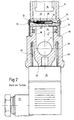
- the known device is used for displaying and / or checking of fluids. Hydraulic fluids are particularly useful for this Question how mineral oil according to DIN 51524, part 1 and 2, water-oil emulsions and synthetic fluids such as phosphate ester based hydraulic fluids.
- the device has two fluid connections 10, 12, wherein in 3, the lower fluid connection 12 is shown in detail.
- the upper fluid connection 10 is advantageous, to avoid inadvertently being inside the fluid-carrying Housing 14 can come to a vacuum or vacuum, which the Longitudinal travel of the float body 16 could impair.
- the Float body 16 is dependent on the fluid level (see FIG. 2) within of the housing 10 guided longitudinally.
- the one shown in Figures 1 to 3 Device is for direct attachment to a hydraulic fluid container, such as a tank, designed, not all of the container in the drawings, but only a container wall 18 partially shown for simplicity is.
- the device is attached to the container wall 18 by means of two banjo bolts 20. Furthermore, the two banjo bolts 20 sealing via container seals 22 with the container wall 18 connected.
- the known device has an electrical switching device 24 (FIG. 2) with a switch contact in the form of a reed switch 26.
- the reed switch 26 is of magnets (not shown) in the Float 16 controllable or switchable. Depending on the training of the reed switch 26 and therefore the switching device 24 can these can be used as NC contacts, NO contacts or change-over contacts.
- the switching signal can also be used for level control use, for example, by the switching device 24 a refill (not shown) for the fluid container.
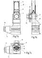
- the housing 14 is made transparent, in particular from Plexiglass, preferably with an elliptical cross-section (cf. Fig.7c).
- the reed switch 26 is of a kind Shrink film 28 comprises in a continuous longitudinal channel of a cross tube 30 led.
- the cross tube 30 passes through with its two free Ends the wall of the housing 14 and is with this end, for example firmly connected via welds (not shown).
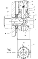
- the Reed switch 26 is via two connecting lines 32 with a plug part 34, which forms a certain type of connector, electrically connected, wherein the connecting part 36 closes the housing 14 at the end.
- the connecting part 36 has a reduced diameter System extension 38 on, the outer peripheral side towards the housing 14 is provided with an inner groove 40, which in turn receives a Sealing ring 42 is used.
- the sealing ring 42 is the interior 44 of the housing 14 separated from the environment in a fluid-tight manner. At the end of the process 38 this widens in one step and forms a ring-like contact surface 46 from which the free end of the housing 14 can be supported.
- the Connection lines 32 themselves reach through the connecting part 36 and are led to plug part 34 in widening connection channels 48. Furthermore, the plug part 34 is connected to the connecting part via a plug plate 50 36 electrically and mechanically connected.
- the plug part 34 has a connector 52 bent at a right angle, via which the fluid level indicator or fluid level control to other facilities, like control and leveling devices (not shown), connectable is.
- the Interior 44 of the housing 14 is like the two fluid connections 10, 12 this is shown in particular in FIG. 3 for the lower fluid connection 12 is fluidly connected to the interior of the container.
- the respective Fluid connection 10,12 on a longitudinal bore 56 which has a Nut connection point 58 opens into the interior 60 of the container.
- the longitudinal bore 56 opens into a transverse bore toward the connecting part 36 62, which in turn carries fluid into the interior 44 of the housing 14 flows.
- the switching device 24 interferes not the relevant fluid flow, but rather can on the switching device 24 over the fluid via said fluid connections 10, 12 act directly on the float body 16, which is dependent of the fluid level in the container indicates the relevant fluid level.
- the upper fluid connection is also comparable to the lower fluid connection 12 10 reached via a screw nut connection (see Fig. 1a, 1b), with a housing cover over the relevant nut connections 64 is preferably made of aluminum material.
- the this case cover 64 has a shop window 66, below which the plexiglass housing 14 appears and the position of the Float body 16 shows a viewer due to level.
- the two connection parts 36 are held together and consequently the position of the housing 14 between the connection parts 36 defined.
- the known solution according to FIGS. 1 to 3 is due to a large number of individual parts characterized. This also results in high assembly costs and an elaborate construction. It has been shown that the tightness at the junction, especially weld, between the sight tube in the form of the housing 14 and the cross tube 30 in particular with extreme temperature fluctuations is not guaranteed.
- the one addressed Sealing ring 42 in the form of a conventional O-ring can be due to the construction should not be easily replaced when worn. Rather, the entire device is then cut through the connecting lines 32 disassemble, which leads to an increased repair effort leads. Due to the design of the lower connection part 36 and the mentioned connector plate 50 is always only the attachment and Use of a connector part 34 provided specifically for the device is possible, so that a modular solution for different connector types is not feasible.
- the electrical switching device 24 is part of the with the housing 14 connectable connector 36, the switching device 24, in particular the reed switch 26, so that it is guided without contact within the housing 14.
- the electrical Switching device 24 with the reed switch 26 in turn acts with at least a magnet (not shown) together in the float body 16 and the connecting lines 32 for the reed switch 26 are this time performed only in the connector 36.
- the connector 36 is again on the outer circumference with the sealing device in the form of the O-ring seal 42 provided that in sealing contact with the inside of the housing 14 is.
- FIG. 4 further shows, the connecting part 36th formed in two parts, the one upper part 68 a receiving space 70 for the switching device 24, in particular the reed switch 26, such forms that the switching device 24 uncovered the float 16 is facing.
- An assembly has therefore been formed between the connecting part 36 and the reed switch housing in the form of the upper Part 68 of the connecting part 36.
- the reed switch 26 is located on the edge surrounded by the upper part 68 of the connecting part 36, inside the perspex tube in the form of the housing 14.
- the relevant arrangement is, as shown in Figure 4 in particular, contact-free to the inside of the housing 14.
- the known shrink tube 28 to protect the Reed switch 26 and the silicone sealing caps 54 for sealing the cross tube 30 are thus omitted. Because of the structure, completely assemble and disassemble the device in a short time.
- the material of the connector 36 and that of the reed switch housing in the form of the upper part 68 made of the same plastic material educated. So the coefficients of linear expansion are the same, whereby by connecting the upper part 68 to the lower connecting part 36 an inseparable, homogeneous connection is created using ultrasonic welding. This means that even with extreme temperatures or temperature fluctuations there are no leaks.
- the reed switch 26 itself is completely cast in the epoxy resin from above. Leave the plastic parts yourself or the like via an injection molding process. manufacture and then connect using an ultrasonic welding process.
- the connecting part 36 and the upper part 68 can, however, be technically also produce in one piece, for example with a lost wax process. However, the latter manufacturing process is expensive, so that the presented two-part solution reduces the manufacturing costs.
- the connecting parts can be the plastic materials mentioned 36 and the upper parts 68 can also be made with other materials.
- the pads of the individual connector parts 34 via the connector plate 50 are designed such that both a standard plug part 72, as shown in Figures 4 and 5, as well as a modified connector part 74, as is the subject of FIGS. 7a, 7b and 7c, can be connected.
- a standard plug part 72 as shown in Figures 4 and 5
- a modified connector part 74 as is the subject of FIGS. 7a, 7b and 7c
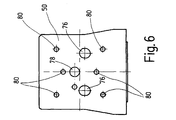
- the plug plate 50 has two holes for this 76 with an elliptical outlet cross-section into which the free ends of the two connecting channels 48 open.
- the further bores 80 also serve for engagement mounting or grounding screws (not shown).
- the prepared ones Hole holes for the mounting screws and the grounding screws are depending on the connector part 34 and therefore depending on the connector type only partially used.
- the grounding hole is located in the center 78 no function, since only plastic parts for the connection part 36 find use and the rest of the voltage for the device is reduced, for example remains below 50 volts.
- the grounding screw for the central central bore 78 is not only used for Fasten, but also as an anti-rotation device for the plug part 34.
- the lower connector 36 is to his free end widened in the manner of a foot in cross section, so that the edge of the modified connector part 74 on the underside of the connecting part 36 can be connected.
- the free end of the connecting part 36 out the connecting channels 48 on the one hand Increase diameter, but otherwise to the toe of connector 36 have an inclination.
- Both for the standard connector part 72 and also for the modified connector part 74 are core bores (not shown) prepared in connector 36. The ones to be used accordingly Screws (not shown) then press in the thread during assembly the device, so that the otherwise necessary mounting bracket, angle seals and metal insert nuts of the previous design can be omitted.
- the device according to the invention is a modular one Kit solution for various connector parts 34 realized that above is also easy to assemble and repair.
Landscapes
- Physics & Mathematics (AREA)
- Fluid Mechanics (AREA)
- General Physics & Mathematics (AREA)
- Switches Operated By Changes In Physical Conditions (AREA)
- Level Indicators Using A Float (AREA)
- Switch Cases, Indication, And Locking (AREA)
Applications Claiming Priority (2)
| Application Number | Priority Date | Filing Date | Title |
|---|---|---|---|
| DE19916953 | 1999-04-15 | ||
| DE19916953A DE19916953A1 (de) | 1999-04-15 | 1999-04-15 | Vorrichtung zum Anzeigen und/oder Kontrollieren von Fluiden |
Publications (2)
| Publication Number | Publication Date |
|---|---|
| EP1046888A1 true EP1046888A1 (fr) | 2000-10-25 |
| EP1046888B1 EP1046888B1 (fr) | 2011-05-18 |
Family
ID=7904605
Family Applications (1)
| Application Number | Title | Priority Date | Filing Date |
|---|---|---|---|
| EP99120093A Expired - Lifetime EP1046888B1 (fr) | 1999-04-15 | 1999-10-20 | Dispositif d'affichage et/ou de contrôle pour des fluides |
Country Status (4)
| Country | Link |
|---|---|
| EP (1) | EP1046888B1 (fr) |
| AT (1) | ATE510193T1 (fr) |
| DE (1) | DE19916953A1 (fr) |
| ES (1) | ES2364180T3 (fr) |
Cited By (3)
| Publication number | Priority date | Publication date | Assignee | Title |
|---|---|---|---|---|
| US7095365B2 (en) | 2003-06-17 | 2006-08-22 | Endress + Hauser Gmbh + Co. Kg | Apparatus for monitoring a field device |
| CN102386017A (zh) * | 2011-11-18 | 2012-03-21 | 上海合璧电子元件有限公司 | 一种电磁式液位开关 |
| EP3333554A1 (fr) * | 2016-12-10 | 2018-06-13 | HYDAC Accessories GmbH | Dispositif destiné à afficher et/ou à réguler l'état d'un fluide |
Families Citing this family (7)
| Publication number | Priority date | Publication date | Assignee | Title |
|---|---|---|---|---|
| DE102004043775B4 (de) * | 2004-09-10 | 2009-02-05 | Hydac Accessories Gmbh | Vorrichtung zum Anzeigen eines Flüssigkeitsstandes mit integriertem Signalelement |
| DE102005018897A1 (de) | 2005-04-22 | 2006-10-26 | Hydac Accessories Gmbh | Vorrichtung zum Anzeigen und/oder Kontrollieren von Fluiden |
| DE102005031987B4 (de) * | 2005-07-08 | 2009-11-26 | Stabil Elektrotechnik Gmbh | Schwimmergesteuerter Niveauschalter für Flüssigkeiten |
| DE102009007655A1 (de) | 2009-02-05 | 2010-08-19 | Hydac Accessories Gmbh | Vorrichtung zum Anzeigen und/oder Kontrollieren von Fluiden |
| DE102009023343A1 (de) | 2009-05-29 | 2010-12-02 | Hydac Accessories Gmbh | Vorrichtung zum Anzeigen und/oder Kontrollieren von Fluiden |
| DE102011053316A1 (de) | 2011-09-06 | 2013-03-07 | Dieter Gössl | Vorrichtung zur elektronischen Füllstandsüberwachung |
| US9003878B2 (en) * | 2011-12-22 | 2015-04-14 | Continental Automotive Systems, Inc. | Variable orientation fluid level sensor with optional slosh guard |
Citations (4)
| Publication number | Priority date | Publication date | Assignee | Title |
|---|---|---|---|---|
| FR2254016A1 (en) * | 1973-12-07 | 1975-07-04 | Tettbro | Domestic bath level warning device - has float which actuates a sound emitter when level reaches predetermined value |
| DE3241250A1 (de) * | 1982-11-09 | 1984-05-10 | Alfred Teves Gmbh, 6000 Frankfurt | Vorrichtung zur qualitativen erfassung der fuellhoehe in fluessigkeitsbehaeltern |
| WO1984004163A1 (fr) * | 1983-04-08 | 1984-10-25 | Fluidtech Gmbh | Dispositif d'affichage du niveau du liquide dans un recipient |
| EP0372909A2 (fr) * | 1988-12-06 | 1990-06-13 | Nippon Air Brake Co., Ltd. | Réservoirs hydrauliques de maître-cylindre |
Family Cites Families (1)
| Publication number | Priority date | Publication date | Assignee | Title |
|---|---|---|---|---|
| JPS551973Y2 (fr) * | 1975-02-25 | 1980-01-19 |
-
1999
- 1999-04-15 DE DE19916953A patent/DE19916953A1/de not_active Withdrawn
- 1999-10-20 ES ES99120093T patent/ES2364180T3/es not_active Expired - Lifetime
- 1999-10-20 EP EP99120093A patent/EP1046888B1/fr not_active Expired - Lifetime
- 1999-10-20 AT AT99120093T patent/ATE510193T1/de active
Patent Citations (4)
| Publication number | Priority date | Publication date | Assignee | Title |
|---|---|---|---|---|
| FR2254016A1 (en) * | 1973-12-07 | 1975-07-04 | Tettbro | Domestic bath level warning device - has float which actuates a sound emitter when level reaches predetermined value |
| DE3241250A1 (de) * | 1982-11-09 | 1984-05-10 | Alfred Teves Gmbh, 6000 Frankfurt | Vorrichtung zur qualitativen erfassung der fuellhoehe in fluessigkeitsbehaeltern |
| WO1984004163A1 (fr) * | 1983-04-08 | 1984-10-25 | Fluidtech Gmbh | Dispositif d'affichage du niveau du liquide dans un recipient |
| EP0372909A2 (fr) * | 1988-12-06 | 1990-06-13 | Nippon Air Brake Co., Ltd. | Réservoirs hydrauliques de maître-cylindre |
Cited By (4)
| Publication number | Priority date | Publication date | Assignee | Title |
|---|---|---|---|---|
| US7095365B2 (en) | 2003-06-17 | 2006-08-22 | Endress + Hauser Gmbh + Co. Kg | Apparatus for monitoring a field device |
| CN102386017A (zh) * | 2011-11-18 | 2012-03-21 | 上海合璧电子元件有限公司 | 一种电磁式液位开关 |
| CN102386017B (zh) * | 2011-11-18 | 2013-12-11 | 上海合璧电子元件有限公司 | 一种电磁式液位开关 |
| EP3333554A1 (fr) * | 2016-12-10 | 2018-06-13 | HYDAC Accessories GmbH | Dispositif destiné à afficher et/ou à réguler l'état d'un fluide |
Also Published As
| Publication number | Publication date |
|---|---|
| EP1046888B1 (fr) | 2011-05-18 |
| ATE510193T1 (de) | 2011-06-15 |
| DE19916953A1 (de) | 2000-11-02 |
| ES2364180T3 (es) | 2011-08-26 |
Similar Documents
| Publication | Publication Date | Title |
|---|---|---|
| DE2217591C3 (de) | Einrichtung zum Auffangen und Anzeigen von Leckkraftstoff an einer jedem Zylinder einer Brennkraftmaschine zugeordneten Kraftstoffeinspritzvorrichtung | |
| EP1046888A1 (fr) | Dispositif d'affichage et/ou de contrôle pour des fluides | |
| DE2337465C2 (de) | Flüssigkeitszähler | |
| DE102005060674C5 (de) | Positionssensor in Stabbauweise sowie Verfahren zum Austausch | |
| DE69511733T2 (de) | Vorrichtung für Wasserversorgungssystem | |
| DE3120725A1 (de) | "druckmessgeraet" | |
| DE102006012810B4 (de) | Schmierstoffverteiler | |
| DE102005025576A1 (de) | Kapazitive Niveausonde | |
| WO1996038671A1 (fr) | Appareillage pneumatique pour l'entretien | |
| EP3333554B1 (fr) | Dispositif destiné à afficher et/ou à réguler l'état d'un fluide | |
| EP0386326B1 (fr) | Système de commande de débit pour dispositifs de graissage | |
| DE2734853C2 (de) | Filter zur Reinigung von Flüssigkeiten | |
| DE3825112C2 (de) | Elektrodenanordnung zur Messung von Füllständen in Milchflußmessern | |
| DE3605388A1 (de) | Elektrohydraulische schaltvorrichtung | |
| DE202005005010U1 (de) | Schmierstoffverteiler | |
| DE102005018897A1 (de) | Vorrichtung zum Anzeigen und/oder Kontrollieren von Fluiden | |
| DE102008032309A1 (de) | Sensoranordnung zur Messung des Zustands einer Flüssigkeit, insbesondere von Öl | |
| DE10357217B4 (de) | Anordnung zur Filterung von Hydraulikflüssigkeit | |
| EP2816329B1 (fr) | Dispositif d'affichage et/ou de contrôle d'un niveau de fluide | |
| DE19525061A1 (de) | Regelsystem zur Regelung von Durchflußmindestmengen und Rückschlagventil | |
| DE3330117C2 (fr) | ||
| DE10012066B4 (de) | Mehrwegeventil (Pilotventilbehälter) | |
| EP0056423A1 (fr) | Soupape hydraulique à plusieurs voies actionnée par un champ électro-magnétique | |
| DE3635241C2 (fr) | ||
| EP3867607B1 (fr) | Dispositif pour l'affichage d'un niveau de fluide |
Legal Events
| Date | Code | Title | Description |
|---|---|---|---|
| PUAI | Public reference made under article 153(3) epc to a published international application that has entered the european phase |
Free format text: ORIGINAL CODE: 0009012 |
|
| AK | Designated contracting states |
Kind code of ref document: A1 Designated state(s): AT BE CH CY DE DK ES FI FR GB GR IE IT LI LU MC NL PT SE |
|
| AX | Request for extension of the european patent |
Free format text: AL;LT;LV;MK;RO;SI |
|
| 17P | Request for examination filed |
Effective date: 20001118 |
|
| AKX | Designation fees paid |
Free format text: AT BE CH CY DE DK ES FI FR GB GR IE IT LI LU MC NL PT SE |
|
| RAP1 | Party data changed (applicant data changed or rights of an application transferred) |
Owner name: HYDAC FLUIDTECHNIK GMBH |
|
| 17Q | First examination report despatched |
Effective date: 20070419 |
|
| GRAP | Despatch of communication of intention to grant a patent |
Free format text: ORIGINAL CODE: EPIDOSNIGR1 |
|
| GRAS | Grant fee paid |
Free format text: ORIGINAL CODE: EPIDOSNIGR3 |
|
| GRAA | (expected) grant |
Free format text: ORIGINAL CODE: 0009210 |
|
| REG | Reference to a national code |
Ref country code: GB Ref legal event code: FG4D Free format text: NOT ENGLISH |
|
| REG | Reference to a national code |
Ref country code: CH Ref legal event code: EP |
|
| REG | Reference to a national code |
Ref country code: IE Ref legal event code: FG4D Free format text: LANGUAGE OF EP DOCUMENT: GERMAN |
|
| REG | Reference to a national code |
Ref country code: DE Ref legal event code: R096 Ref document number: 59915268 Country of ref document: DE Effective date: 20110630 |
|
| REG | Reference to a national code |
Ref country code: ES Ref legal event code: FG2A Ref document number: 2364180 Country of ref document: ES Kind code of ref document: T3 Effective date: 20110826 |
|
| REG | Reference to a national code |
Ref country code: NL Ref legal event code: VDEP Effective date: 20110518 |
|
| PG25 | Lapsed in a contracting state [announced via postgrant information from national office to epo] |
Ref country code: SE Free format text: LAPSE BECAUSE OF FAILURE TO SUBMIT A TRANSLATION OF THE DESCRIPTION OR TO PAY THE FEE WITHIN THE PRESCRIBED TIME-LIMIT Effective date: 20110518 Ref country code: PT Free format text: LAPSE BECAUSE OF FAILURE TO SUBMIT A TRANSLATION OF THE DESCRIPTION OR TO PAY THE FEE WITHIN THE PRESCRIBED TIME-LIMIT Effective date: 20110919 |
|
| PG25 | Lapsed in a contracting state [announced via postgrant information from national office to epo] |
Ref country code: GR Free format text: LAPSE BECAUSE OF FAILURE TO SUBMIT A TRANSLATION OF THE DESCRIPTION OR TO PAY THE FEE WITHIN THE PRESCRIBED TIME-LIMIT Effective date: 20110819 Ref country code: FI Free format text: LAPSE BECAUSE OF FAILURE TO SUBMIT A TRANSLATION OF THE DESCRIPTION OR TO PAY THE FEE WITHIN THE PRESCRIBED TIME-LIMIT Effective date: 20110518 Ref country code: CY Free format text: LAPSE BECAUSE OF FAILURE TO SUBMIT A TRANSLATION OF THE DESCRIPTION OR TO PAY THE FEE WITHIN THE PRESCRIBED TIME-LIMIT Effective date: 20110518 |
|
| REG | Reference to a national code |
Ref country code: IE Ref legal event code: FD4D |
|
| PG25 | Lapsed in a contracting state [announced via postgrant information from national office to epo] |
Ref country code: NL Free format text: LAPSE BECAUSE OF FAILURE TO SUBMIT A TRANSLATION OF THE DESCRIPTION OR TO PAY THE FEE WITHIN THE PRESCRIBED TIME-LIMIT Effective date: 20110518 |
|
| PG25 | Lapsed in a contracting state [announced via postgrant information from national office to epo] |
Ref country code: IE Free format text: LAPSE BECAUSE OF FAILURE TO SUBMIT A TRANSLATION OF THE DESCRIPTION OR TO PAY THE FEE WITHIN THE PRESCRIBED TIME-LIMIT Effective date: 20110518 |
|
| PG25 | Lapsed in a contracting state [announced via postgrant information from national office to epo] |
Ref country code: DK Free format text: LAPSE BECAUSE OF FAILURE TO SUBMIT A TRANSLATION OF THE DESCRIPTION OR TO PAY THE FEE WITHIN THE PRESCRIBED TIME-LIMIT Effective date: 20110518 |
|
| PLBE | No opposition filed within time limit |
Free format text: ORIGINAL CODE: 0009261 |
|
| STAA | Information on the status of an ep patent application or granted ep patent |
Free format text: STATUS: NO OPPOSITION FILED WITHIN TIME LIMIT |
|
| 26N | No opposition filed |
Effective date: 20120221 |
|
| BERE | Be: lapsed |
Owner name: HYDAC FLUIDTECHNIK G.M.B.H. Effective date: 20111031 |
|
| PG25 | Lapsed in a contracting state [announced via postgrant information from national office to epo] |
Ref country code: MC Free format text: LAPSE BECAUSE OF NON-PAYMENT OF DUE FEES Effective date: 20111031 |
|
| REG | Reference to a national code |
Ref country code: CH Ref legal event code: PL |
|
| REG | Reference to a national code |
Ref country code: DE Ref legal event code: R097 Ref document number: 59915268 Country of ref document: DE Effective date: 20120221 |
|
| PG25 | Lapsed in a contracting state [announced via postgrant information from national office to epo] |
Ref country code: BE Free format text: LAPSE BECAUSE OF NON-PAYMENT OF DUE FEES Effective date: 20111031 Ref country code: CH Free format text: LAPSE BECAUSE OF NON-PAYMENT OF DUE FEES Effective date: 20111031 Ref country code: LI Free format text: LAPSE BECAUSE OF NON-PAYMENT OF DUE FEES Effective date: 20111031 |
|
| PG25 | Lapsed in a contracting state [announced via postgrant information from national office to epo] |
Ref country code: LU Free format text: LAPSE BECAUSE OF NON-PAYMENT OF DUE FEES Effective date: 20111020 |
|
| REG | Reference to a national code |
Ref country code: FR Ref legal event code: PLFP Year of fee payment: 18 |
|
| REG | Reference to a national code |
Ref country code: FR Ref legal event code: PLFP Year of fee payment: 19 |
|
| REG | Reference to a national code |
Ref country code: FR Ref legal event code: PLFP Year of fee payment: 20 |
|
| PGFP | Annual fee paid to national office [announced via postgrant information from national office to epo] |
Ref country code: FR Payment date: 20180824 Year of fee payment: 20 |
|
| PGFP | Annual fee paid to national office [announced via postgrant information from national office to epo] |
Ref country code: GB Payment date: 20180807 Year of fee payment: 20 |
|
| PGFP | Annual fee paid to national office [announced via postgrant information from national office to epo] |
Ref country code: AT Payment date: 20181024 Year of fee payment: 20 Ref country code: DE Payment date: 20181031 Year of fee payment: 20 |
|
| PGFP | Annual fee paid to national office [announced via postgrant information from national office to epo] |
Ref country code: ES Payment date: 20181108 Year of fee payment: 20 Ref country code: IT Payment date: 20181023 Year of fee payment: 20 |
|
| REG | Reference to a national code |
Ref country code: DE Ref legal event code: R071 Ref document number: 59915268 Country of ref document: DE |
|
| REG | Reference to a national code |
Ref country code: GB Ref legal event code: PE20 Expiry date: 20191019 |
|
| REG | Reference to a national code |
Ref country code: AT Ref legal event code: MK07 Ref document number: 510193 Country of ref document: AT Kind code of ref document: T Effective date: 20191020 |
|
| PG25 | Lapsed in a contracting state [announced via postgrant information from national office to epo] |
Ref country code: GB Free format text: LAPSE BECAUSE OF EXPIRATION OF PROTECTION Effective date: 20191019 |
|
| REG | Reference to a national code |
Ref country code: ES Ref legal event code: FD2A Effective date: 20200904 |
|
| PG25 | Lapsed in a contracting state [announced via postgrant information from national office to epo] |
Ref country code: ES Free format text: LAPSE BECAUSE OF EXPIRATION OF PROTECTION Effective date: 20191021 |