EP3333554B1 - Dispositif destiné à afficher et/ou à réguler l'état d'un fluide - Google Patents
Dispositif destiné à afficher et/ou à réguler l'état d'un fluide Download PDFInfo
- Publication number
- EP3333554B1 EP3333554B1 EP17001903.8A EP17001903A EP3333554B1 EP 3333554 B1 EP3333554 B1 EP 3333554B1 EP 17001903 A EP17001903 A EP 17001903A EP 3333554 B1 EP3333554 B1 EP 3333554B1
- Authority
- EP
- European Patent Office
- Prior art keywords
- connection body
- connection
- channel
- accordance
- fluid
- Prior art date
- Legal status (The legal status is an assumption and is not a legal conclusion. Google has not performed a legal analysis and makes no representation as to the accuracy of the status listed.)
- Active
Links
Images


Classifications
-
- G—PHYSICS
- G01—MEASURING; TESTING
- G01F—MEASURING VOLUME, VOLUME FLOW, MASS FLOW OR LIQUID LEVEL; METERING BY VOLUME
- G01F23/00—Indicating or measuring liquid level or level of fluent solid material, e.g. indicating in terms of volume or indicating by means of an alarm
- G01F23/30—Indicating or measuring liquid level or level of fluent solid material, e.g. indicating in terms of volume or indicating by means of an alarm by floats
- G01F23/64—Indicating or measuring liquid level or level of fluent solid material, e.g. indicating in terms of volume or indicating by means of an alarm by floats of the free float type without mechanical transmission elements
- G01F23/72—Indicating or measuring liquid level or level of fluent solid material, e.g. indicating in terms of volume or indicating by means of an alarm by floats of the free float type without mechanical transmission elements using magnetically actuated indicating means
- G01F23/74—Indicating or measuring liquid level or level of fluent solid material, e.g. indicating in terms of volume or indicating by means of an alarm by floats of the free float type without mechanical transmission elements using magnetically actuated indicating means for sensing changes in level only at discrete points
Definitions
- the invention relates to a device for indicating and / or controlling fluid conditions having the features in the preamble of claim 1.
- Such devices are used to indicate the level of a liquid within a container or tank, the apparatus being mounted outside the container but connected to it in the manner of communicating tubes via at least one fluid port.
- the respective current level can be visually displayed, for example by visually observing the position of the float body, or it can be generated by the display device containing a reed switch, an electrical switching signal in such a way that a magnet containing in the float body at a predetermined float position with its magnetic field triggers a switching operation of the reed switch.
- the actions necessary to reach the relevant level can be made manually or automatically.
- hydraulic fluids such as mineral oil according to DIN 51524, parts 1 and 2, fuels, water-oil emulsions and synthetic fluids, such as hydraulic fluids.
- the riser can be configured as a glass or Plexiglas tube, so that the position of the float body can be observed by a viewer.
- the connecting body as a carrier for the reed switch on a top part which is connected to the lower part of the connecting body by means of ultrasonic welding, the reed switch at the top of the upper part, and thus within the riser, exposed.
- the electrical connection lines for the reed switch are passed through aligned channels of the upper part of the connector body and the lower part of the connector body, so they run through the welding area between the upper and lower part.
- the welded joint must therefore be designed in such a way that the passage for the connection leads remains free, but at the same time they are sealed at the weld. The preparation of the connection body is therefore relatively expensive.
- the US 3,849,770 describes a device for indicating and / or controlling fluid conditions according to the preamble of claim 1, having at least one fluid port, which opens via a connecting body in a riser in which a fluid level adjusting float body is movably guided along a travel axis, wherein a the position of the float body recognizing display device comprises a reed switch which triggers a switching operation in an electrical switching device at a predetermined fluid level.
- Another device for indicating and / or controlling fluid conditions is from the EP 1 046 888 A1 out.
- the invention has the object to provide a device of the type mentioned is available, which is characterized by a simple and rational producible design by a favorable performance.
- an essential feature of the invention is that the connecting body is integrally formed and includes a channel which, based on the travel axis of the float body, extends in an oblique direction to the upper boundary of the connecting body, at its upper Closing of the connector body is closely adjacent end closed and receives the reed switch in adjacent to this closed end position.
- the connection body eliminates the cost of producing a shell and the ultrasonic welding process and the associated risk of the formation of leaks.
- the arrangement may be such that the terminal body is in the form of a block having spaced sidewalls in parallel planes, the sloping channel having an open end extending from a side wall.
- the reed switch can be inserted and installed from the open end of the channel located on the side of the connection body.
- the connecting body between the side walls a centrally located, parallel to their planes extending fluid passage, wherein in the region between the fluid passage and the mouth of the oblique channel having side wall extending parallel to this branch channel, which opens with its upper end in the oblique channel and open at the lower end of the connecting body.
- the arrangement may be such that between the fluid passage and the upper boundary of the connection body, a fluid communication channel is formed, which runs along the side wall, which is opposite to the side wall, at which the mouth of the oblique channel is located.
- a fluid communication channel is formed, which runs along the side wall, which is opposite to the side wall, at which the mouth of the oblique channel is located.
- this lateral displacement of the connecting channel is the mouth to the riser at the upper boundary of the connector body adjacent to the closed end of the reed switch receiving channel.
- the upper limit of the connecting body can be formed by the end of a peg-like approach thereof, which has an appropriate engagement in the end of the riser enabling outer shape and a flat, for protruding the plant of the end of the riser serving surface of the connection body.
- an oval-shaped riser results in a correspondingly oval outline of the approach to which a circumferential groove can be formed, which receives a sealing ring which forms the seal of the riser pipe on the connection body.
- the injection-molded from a plastic material connection body on its underside a centrally located seat for a metallic threaded sleeve having an internal thread for forming a screw with an end body containing contact elements for electrical connection to the reed switch.
- connection body can advantageously be such that the side walls located on both sides of the fluid passage of the connection body are planar and at a step adjacent to the lower end transition into outwardly projecting wall sections, which form an enclosure for an elastomeric inserted between connection body and end body Form ring body.
- This can advantageously be designed such that it comprises a facing out of the ring plane peripheral edge a facing end portion of the end body.
- the position of the ring body is clearly defined by formed form-fitting, which facilitates the assembly process.
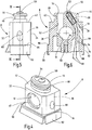
- the exemplary embodiment has fluid connections in the form of hollow screws 2, whose coaxial inner bore 4 (FIG. Fig. 3 ), which is open at the side facing away from the screw head 6, is in fluid communication with a container or tank, not shown.
- the in the Fig. 1 to 3 underlying hollow screw 2 passes through a formed in a connecting body 8 fluid passage 10, and the upper hollow screw 2 passes through a formed in an upper connecting body 12 fluid passage 14.
- each hollow screw 2 With a nut 16 which sits on the head 6 opposite threaded portion of each hollow screw 2, is a housing part 18 fixed in the form of a U-shaped rail on the connector body 8 and the upper connector body 12, wherein the housing part 18 is sealed via an O-ring 20 on the connector body 8 and the upper connector body 12 and between the nuts 16 and the connector body 8 and the connecting body 12 are each a flat gasket 22.
- the O-rings 20 and the flat gasket 22 form at the lower connection body 8 and at the upper connection body 12 respectively the sealing of their fluid passage 10 and 14.
- a recessed in the front of the housing part 18 window 26 allows the observation of a field of view of a riser 28 in the form of a plexiglass or glass tube extending between connector body 8 and connecting body 12, at the lower connector body 8 with the fluid passage 10 in conjunction and the upper connector body 12 is connected to the fluid passage 14 in connection.
- the 4 to 6 show details of the connector body 8, which is part of a display device which provides a display signal at a position corresponding to a predetermined fluid level of a float body 30 located in the riser 28.
- the injection-molded as a one-piece component of a thermoplastic material connecting body 8 has the shape of a block with end wall 32 and rear wall 34, apart from lateral bevels, are planar and parallel to each other. At right angles thereto extending side walls 36 and 38 are also over a large area flat.
- the associated fluid passage 10 extends in a central position of the end wall 32 to the rear wall 34, wherein the bore diameter is widened in the end wall 32 adjacent to the end region such that a seat 40 is formed for the O-ring 20 which extends between the connection body 8 and the Housing part 18 is located, see Fig. 3 ,
- a surface 42 extending in a horizontal plane is formed on the block of the connection body 8, from which a peg-like projection 44 projects upwards, which forms the upper boundary of the connection body 8.
- the projection 44 has an oval or round outline adapted to the oval or round cross-section of the riser 28 and has a circumferential annular groove 46 for an O-ring 48.
- the riser 28 abuts with its lower end on the surface 42 of the connection body 8 and the projection 44 extends into the interior of the riser, the O-ring 48 forms the seal of the riser 28 at the base 44.
- the upper end of the riser 28 is located also on a surface of the upper connecting body 12, wherein a corresponding O-ring 48 forms the seal between riser 28 and upper connecting body 12.
- a button-like projection 50 which is formed centrally located on the upper boundary of the lug 44, forms a very limited contact surface for the float body 30 located in the lowest end position and thereby prevents sticking of the float body 30 located in the lower end position.
- a vertical connecting channel 52 is provided, which is to the axis of the bore of the fluid passage 10 in the direction of Fig. 6
- Left side wall 38 is offset so that it opens at the upper boundary of the lug 44 at a location located adjacent to the projection 50 point 54.
- the connection body 8 forms part of the display device and for this purpose forms the receptacle for a reed switch 56 (FIG. Fig. 6 ).
- a channel 58 is provided, which is in the form of a blind bore from an input point 60 ago, located on the in 4 and 6
- Right side wall 36 is located at about half their height and extends obliquely to the upper boundary of the neck 44 out where the channel 58 at a very short distance from the upper limit of the neck 44 at the in Fig. 6 closed at 62 point.
- the reed switch 56 is received and secured by potting compound.
- branch channel 64 which extends between this side wall 36 and the fluid passage 10 in the vertical direction and is open at the bottom 66 of the connecting body 8.
- the electrical connection with the reed switch 56 forming conductor 68 are laid.
- an end body 70 is set, in which enter via the branch channel 64 supplied two electrical conductors 68 of the reed switch 56.
- the end body 70 is composed of an upper fastening part 72 and a lower clamping part 74, of which the fastening part 72 can be screwed to the connecting body 8 and the lower clamping part 74 has connection terminals 76 for the conductors 68 and a terminal 78 for a ground connection.
- the fastening part 72 has a bore 80 which is provided for the passage of a (not shown) countersunk screw.
- FIG. 3 shows, between the upper part 72 of the end body 70 and the bottom 66 of the connecting body 8, an elastomeric ring body 86 is inserted, which comprises a ring-plane projecting from the bottom peripheral edge 88, the upper end portion of the fastening part 72 and is thereby positioned on the fastening part 72.
- the annular body 86 is on two opposite sides, namely on the side walls 36 and 38 of the connecting body 8 adjacent sides, overlapped and bordered by the projecting ends of wall portions 90 and 92 which at steps 94 and 96 of the side walls 36 and 38 are offset to the outside.
- the device may be calibrated such that the reed switch 56 switches by the action of the magnetic field generated by the magnet of the float body 30 as soon as the float body 30 assumes a position corresponding to a predetermined minimum fluid level.
- the reed switch 56 can operate in a known manner as NO, NC or changeover according to the associated electrical switching device to generate a warning signal when falling below a predetermined fluid level, due to which operational measures, such as the refilling of the container, manually or via the switching device are triggered automatically.
- the respective position of the float body 30 and thus the height of the fluid level is visually observable via the viewing window 26 in the housing part 18.
Landscapes
- Physics & Mathematics (AREA)
- Fluid Mechanics (AREA)
- General Physics & Mathematics (AREA)
- Level Indicators Using A Float (AREA)
Claims (9)
- Dispositif d'affichage et/ou de contrôle d'états de fluide, comprenant au moins un raccord (2) pour du fluide, qui débouche par un corps (8) de raccord dans un tuyau (28) ascendant, dans lequel un corps (30) flottant, se réglant sur le niveau de fluide, est guidé avec possibilité de se déplacer suivant un axe de déplacement, dans lequel un dispositif d'affichage, reconnaissant la position du corps (30) flottant, a un interrupteur (56) de Reed, qui, à un niveau de fluide donné à l'avance, déclenche une opération de coupure dans un dispositif électrique de coupure, caractérisé en ce que le corps (8) de raccord est constitué d'une seule pièce et comporte un conduit (58), qui, par rapport à l'axe de déplacement du corps (30) flottant, s'étend dans une direction inclinée vers la démarcation (44) supérieure du corps (8) de raccord, est fermé à son extrémité (62) voisine de la démarcation (44) supérieure du corps de raccord et reçoit l'interrupteur (56) de Reed dans une position voisine de cette extrémité (62) fermée.
- Dispositif suivant la revendication 1, caractérisé en ce que le corps (8) de raccord a la forme d'un bloc ayant des parois (36, 38) latérales s'étendant dans des plans parallèles à distance l'un de l'autre et en ce que le conduit (58) incliné sort, par son extrémité (60) ouverte, d'une paroi (36) latérale.
- Dispositif suivant la revendication 1 ou 2, caractérisé en ce que le corps (8) de raccord a, entre les parois (36, 38) latérales, un passage (10) pour du fluide, disposé centralement et s'étendant parallèlement à leurs plans, et en ce que, dans la région entre le passage (10) pour du fluide et la paroi (36) latérale ayant l'embouchure du conduit (58) incliné, s'étend, parallèlement à celle-ci, un conduit (64) de dérivation, qui débouche, par son extrémité supérieure, dans le conduit (56) incliné et est ouvert du côté (66) inférieur du corps (8) de raccord.
- Dispositif suivant l'une des revendication précédentes, caractérisé en ce qu'entre le passage (10) pour du fluide et la démarcation (44) supérieure du corps (8) de raccord, est formé un conduit (52) de liaison pour du fluide, qui s'étend le long de la paroi (38) latérale opposée à la paroi (36) latérale où se trouve l'embouchure du conduit (58) incliné.
- Dispositif suivant l'une des revendications précédentes, caractérisé en ce que la démarcation supérieure du corps (8) de raccord est formée par l'extrémité d'un appendice (44) de type en tenon de celui-ci, qui possède une forme extérieure permettant une pénétration avec adaptation dans l'extrémité du tuyau (28) ascendant et qui fait saillie d'une surface (42), plane et servant à l'application de l'extrémité du tuyau (28) ascendant, du corps (8) de raccord.
- Dispositif suivant l'une des revendications précédentes, caractérisé en ce que, dans l'appendice (44), est constituée une rainure (46) de pourtour pour recevoir une bague (48) d'étanchéité formant l'étanchéité du tuyau (28) ascendant sur le corps (8) de raccord.
- Dispositif suivant l'une des revendications précédentes, caractérisé en ce que, du côté (66) inférieur du corps (8) de raccord mené par injection en matière plastique, est prévu un siège (84) disposé de manière centrale pour une douille (82) filetée, qui a un taraudage pour former un vissage avec une pièce (70) d'extrémité, qui contient des éléments de contact pour la liaison électrique avec l'interrupteur (56) Reed.
- Dispositif suivant l'une des revendications précédentes, caractérisé en ce que les parois (36, 38) latérales, se trouvant des deux côtés du passage (10) pour du fluide du corps (8) de raccord, sont planes suivant un plan et se transforment, sur un palier (94, 96) voisin de l'extrémité inférieure, en des parties (90, 92) de paroi en saillie décalées vers l'extérieur, qui forment une bordure d'un corps (86) annulaire en élastomère inséré entre le corps (8) de raccord et le corps (70) d'extrémité.
- Dispositif suivant l'une des revendications précédentes, caractérisé en ce que le corps (86) annulaire entoure, par un bord (88) périphérique en saillie du plan annulaire, la partie d'extrémité tournée vers lui du corps (70) d'extrémité.
Applications Claiming Priority (1)
| Application Number | Priority Date | Filing Date | Title |
|---|---|---|---|
| DE102016014778.4A DE102016014778A1 (de) | 2016-12-10 | 2016-12-10 | Vorrichtung zum Anzeigen und/oder Kontrollieren von Fluidzuständen |
Publications (2)
| Publication Number | Publication Date |
|---|---|
| EP3333554A1 EP3333554A1 (fr) | 2018-06-13 |
| EP3333554B1 true EP3333554B1 (fr) | 2019-10-23 |
Family
ID=60452332
Family Applications (1)
| Application Number | Title | Priority Date | Filing Date |
|---|---|---|---|
| EP17001903.8A Active EP3333554B1 (fr) | 2016-12-10 | 2017-11-22 | Dispositif destiné à afficher et/ou à réguler l'état d'un fluide |
Country Status (2)
| Country | Link |
|---|---|
| EP (1) | EP3333554B1 (fr) |
| DE (1) | DE102016014778A1 (fr) |
Families Citing this family (2)
| Publication number | Priority date | Publication date | Assignee | Title |
|---|---|---|---|---|
| DE102019001310A1 (de) * | 2019-02-23 | 2020-08-27 | Hydac Accessories Gmbh | Vorrichtung zum Anzeigen eines Fluidniveaus |
| CN114161925A (zh) * | 2021-11-30 | 2022-03-11 | 东风商用车有限公司 | 一种可观测液面的结构和油箱 |
Citations (1)
| Publication number | Priority date | Publication date | Assignee | Title |
|---|---|---|---|---|
| DE9307564U1 (de) * | 1993-05-18 | 1993-10-07 | Honsberg & Co KG, 42897 Remscheid | Durchflußschalter |
Family Cites Families (9)
| Publication number | Priority date | Publication date | Assignee | Title |
|---|---|---|---|---|
| JPS5153433Y2 (fr) * | 1972-04-25 | 1976-12-21 | ||
| IT1020103B (it) * | 1974-08-22 | 1977-12-20 | Benditalia Spa | Indicatore del livello di flui do in un serbatoio |
| DE7904635U1 (de) * | 1978-02-27 | 1979-06-13 | Gratzmuller, Jean Louis, Neuilly- Sur-Seine, Hauts-De-Seine (Frankreich) | Hydro-pneumatischer Speicherkraftzylinder mit einem Leckfühler für das Gas |
| US4772386A (en) * | 1986-05-30 | 1988-09-20 | Autotrol Corporation | Filter with liquid meter |
| DE19916953A1 (de) * | 1999-04-15 | 2000-11-02 | Fluidtech Gmbh | Vorrichtung zum Anzeigen und/oder Kontrollieren von Fluiden |
| EP1250495B1 (fr) * | 1999-11-29 | 2005-07-27 | Watersave Enterprises Limited | Systeme de trop-plein |
| US20030033868A1 (en) * | 2001-08-16 | 2003-02-20 | Hermetic Switch, Inc. | Valve monitor |
| DE102012015009A1 (de) * | 2012-07-28 | 2014-01-30 | GM Global Technology Operations LLC (n. d. Gesetzen des Staates Delaware) | Messeinrichtung zur Messung eines Füssigkeitspegels und Flüssigkeitsbehälter mit einer solchen Messeinrichtung |
| EP2944850B1 (fr) * | 2014-05-12 | 2017-07-12 | HAWE Hydraulik SE | Capteur de position résistant à la pression |
-
2016
- 2016-12-10 DE DE102016014778.4A patent/DE102016014778A1/de not_active Withdrawn
-
2017
- 2017-11-22 EP EP17001903.8A patent/EP3333554B1/fr active Active
Patent Citations (1)
| Publication number | Priority date | Publication date | Assignee | Title |
|---|---|---|---|---|
| DE9307564U1 (de) * | 1993-05-18 | 1993-10-07 | Honsberg & Co KG, 42897 Remscheid | Durchflußschalter |
Also Published As
| Publication number | Publication date |
|---|---|
| DE102016014778A1 (de) | 2018-06-14 |
| EP3333554A1 (fr) | 2018-06-13 |
Similar Documents
| Publication | Publication Date | Title |
|---|---|---|
| DE3242945C2 (de) | Ventilanordnung | |
| DE102007023070B4 (de) | Ausgleichsbehälter für eine hydraulische Kraftfahrzeugbremsanlage | |
| DE3642669A1 (de) | Eigenmediumgesteuertes, durch ein vorzugsweise elektromagnetisch betaetigtes steuerventil ausloesbares ventil | |
| EP3333554B1 (fr) | Dispositif destiné à afficher et/ou à réguler l'état d'un fluide | |
| EP0305821B1 (fr) | Dispositif pour fermer l'embranchement d'un tube | |
| DE102006005529B4 (de) | Kunststoffbehälter mit wenigstens einer Elektrode aus elektrisch leitfähigem Kunststoff | |
| EP2256469B1 (fr) | Dispositif d'affichage et/ou de contrôle de fluides | |
| EP2072967B1 (fr) | Capteur électronique et procédé de fabrication d'un capteur | |
| EP1046888B1 (fr) | Dispositif d'affichage et/ou de contrôle pour des fluides | |
| DE102009007655A1 (de) | Vorrichtung zum Anzeigen und/oder Kontrollieren von Fluiden | |
| DE102006058069A1 (de) | Einbauelektrodenvorrichtung | |
| WO2008107053A1 (fr) | Débitmètre à tourbillons pour enregistrer la vitesse d'écoulement dans une conduite | |
| DE10330563B4 (de) | Box für eine elektrische Verbindung | |
| EP1091465B1 (fr) | Traversée de câble | |
| EP0658511B1 (fr) | Système pour remplir des bouteilles, des boîtes ou des récipients similaires avec un produit liquide | |
| EP0060289A1 (fr) | Anode reactive avec indicateur de consommation et capsule de plongee pour sonde thermique. | |
| EP3867607B1 (fr) | Dispositif pour l'affichage d'un niveau de fluide | |
| DE29915384U1 (de) | Kombination aus einer Haupteinheit und wenigstens einer Anbau-Funktionseinheit | |
| DE102011112227B4 (de) | Absperrvorrichtung für die Wasserzufuhr zu einem Hydranten | |
| EP2072695B2 (fr) | Réservoir de chasse encastré doté d'un élément de raccordement destiné à raccorder une conduite d'alimentation en eau et procédé de raccordement d'un réservoir de chasse encastré sur une conduite d'alimentation en eau | |
| WO2008138310A1 (fr) | Appariemment pour contact à fiches | |
| DE10161416A1 (de) | Behälter, insbesondere Paletteninnenbehälter | |
| DE102006022540A1 (de) | Steckerteil mit einer aus zwei Halbschalen gebildeten Geldichtung | |
| DE102008023431A1 (de) | Flüssigkeitsbehandlungsanordnung, insbesondere Wasserbehandlungsanordnung | |
| EP2604986A2 (fr) | Dispositif d'affichage de la hauteur du niveau de remplissage de fluides |
Legal Events
| Date | Code | Title | Description |
|---|---|---|---|
| PUAI | Public reference made under article 153(3) epc to a published international application that has entered the european phase |
Free format text: ORIGINAL CODE: 0009012 |
|
| STAA | Information on the status of an ep patent application or granted ep patent |
Free format text: STATUS: THE APPLICATION HAS BEEN PUBLISHED |
|
| AK | Designated contracting states |
Kind code of ref document: A1 Designated state(s): AL AT BE BG CH CY CZ DE DK EE ES FI FR GB GR HR HU IE IS IT LI LT LU LV MC MK MT NL NO PL PT RO RS SE SI SK SM TR |
|
| AX | Request for extension of the european patent |
Extension state: BA ME |
|
| STAA | Information on the status of an ep patent application or granted ep patent |
Free format text: STATUS: REQUEST FOR EXAMINATION WAS MADE |
|
| 17P | Request for examination filed |
Effective date: 20181213 |
|
| RIC1 | Information provided on ipc code assigned before grant |
Ipc: G01F 23/74 20060101AFI20190503BHEP |
|
| GRAP | Despatch of communication of intention to grant a patent |
Free format text: ORIGINAL CODE: EPIDOSNIGR1 |
|
| INTG | Intention to grant announced |
Effective date: 20190614 |
|
| STAA | Information on the status of an ep patent application or granted ep patent |
Free format text: STATUS: GRANT OF PATENT IS INTENDED |
|
| GRAS | Grant fee paid |
Free format text: ORIGINAL CODE: EPIDOSNIGR3 |
|
| GRAA | (expected) grant |
Free format text: ORIGINAL CODE: 0009210 |
|
| STAA | Information on the status of an ep patent application or granted ep patent |
Free format text: STATUS: THE PATENT HAS BEEN GRANTED |
|
| AK | Designated contracting states |
Kind code of ref document: B1 Designated state(s): AL AT BE BG CH CY CZ DE DK EE ES FI FR GB GR HR HU IE IS IT LI LT LU LV MC MK MT NL NO PL PT RO RS SE SI SK SM TR |
|
| REG | Reference to a national code |
Ref country code: GB Ref legal event code: FG4D Free format text: NOT ENGLISH |
|
| REG | Reference to a national code |
Ref country code: CH Ref legal event code: EP |
|
| REG | Reference to a national code |
Ref country code: IE Ref legal event code: FG4D Free format text: LANGUAGE OF EP DOCUMENT: GERMAN |
|
| REG | Reference to a national code |
Ref country code: DE Ref legal event code: R096 Ref document number: 502017002611 Country of ref document: DE |
|
| REG | Reference to a national code |
Ref country code: AT Ref legal event code: REF Ref document number: 1194165 Country of ref document: AT Kind code of ref document: T Effective date: 20191115 |
|
| REG | Reference to a national code |
Ref country code: NL Ref legal event code: MP Effective date: 20191023 |
|
| REG | Reference to a national code |
Ref country code: LT Ref legal event code: MG4D |
|
| PG25 | Lapsed in a contracting state [announced via postgrant information from national office to epo] |
Ref country code: LV Free format text: LAPSE BECAUSE OF FAILURE TO SUBMIT A TRANSLATION OF THE DESCRIPTION OR TO PAY THE FEE WITHIN THE PRESCRIBED TIME-LIMIT Effective date: 20191023 Ref country code: SE Free format text: LAPSE BECAUSE OF FAILURE TO SUBMIT A TRANSLATION OF THE DESCRIPTION OR TO PAY THE FEE WITHIN THE PRESCRIBED TIME-LIMIT Effective date: 20191023 Ref country code: NL Free format text: LAPSE BECAUSE OF FAILURE TO SUBMIT A TRANSLATION OF THE DESCRIPTION OR TO PAY THE FEE WITHIN THE PRESCRIBED TIME-LIMIT Effective date: 20191023 Ref country code: GR Free format text: LAPSE BECAUSE OF FAILURE TO SUBMIT A TRANSLATION OF THE DESCRIPTION OR TO PAY THE FEE WITHIN THE PRESCRIBED TIME-LIMIT Effective date: 20200124 Ref country code: NO Free format text: LAPSE BECAUSE OF FAILURE TO SUBMIT A TRANSLATION OF THE DESCRIPTION OR TO PAY THE FEE WITHIN THE PRESCRIBED TIME-LIMIT Effective date: 20200123 Ref country code: PL Free format text: LAPSE BECAUSE OF FAILURE TO SUBMIT A TRANSLATION OF THE DESCRIPTION OR TO PAY THE FEE WITHIN THE PRESCRIBED TIME-LIMIT Effective date: 20191023 Ref country code: LT Free format text: LAPSE BECAUSE OF FAILURE TO SUBMIT A TRANSLATION OF THE DESCRIPTION OR TO PAY THE FEE WITHIN THE PRESCRIBED TIME-LIMIT Effective date: 20191023 Ref country code: PT Free format text: LAPSE BECAUSE OF FAILURE TO SUBMIT A TRANSLATION OF THE DESCRIPTION OR TO PAY THE FEE WITHIN THE PRESCRIBED TIME-LIMIT Effective date: 20200224 Ref country code: FI Free format text: LAPSE BECAUSE OF FAILURE TO SUBMIT A TRANSLATION OF THE DESCRIPTION OR TO PAY THE FEE WITHIN THE PRESCRIBED TIME-LIMIT Effective date: 20191023 Ref country code: BG Free format text: LAPSE BECAUSE OF FAILURE TO SUBMIT A TRANSLATION OF THE DESCRIPTION OR TO PAY THE FEE WITHIN THE PRESCRIBED TIME-LIMIT Effective date: 20200123 |
|
| PG25 | Lapsed in a contracting state [announced via postgrant information from national office to epo] |
Ref country code: IS Free format text: LAPSE BECAUSE OF FAILURE TO SUBMIT A TRANSLATION OF THE DESCRIPTION OR TO PAY THE FEE WITHIN THE PRESCRIBED TIME-LIMIT Effective date: 20200224 Ref country code: HR Free format text: LAPSE BECAUSE OF FAILURE TO SUBMIT A TRANSLATION OF THE DESCRIPTION OR TO PAY THE FEE WITHIN THE PRESCRIBED TIME-LIMIT Effective date: 20191023 Ref country code: RS Free format text: LAPSE BECAUSE OF FAILURE TO SUBMIT A TRANSLATION OF THE DESCRIPTION OR TO PAY THE FEE WITHIN THE PRESCRIBED TIME-LIMIT Effective date: 20191023 |
|
| PG25 | Lapsed in a contracting state [announced via postgrant information from national office to epo] |
Ref country code: AL Free format text: LAPSE BECAUSE OF FAILURE TO SUBMIT A TRANSLATION OF THE DESCRIPTION OR TO PAY THE FEE WITHIN THE PRESCRIBED TIME-LIMIT Effective date: 20191023 |
|
| REG | Reference to a national code |
Ref country code: DE Ref legal event code: R097 Ref document number: 502017002611 Country of ref document: DE |
|
| PG2D | Information on lapse in contracting state deleted |
Ref country code: IS |
|
| PG25 | Lapsed in a contracting state [announced via postgrant information from national office to epo] |
Ref country code: LU Free format text: LAPSE BECAUSE OF NON-PAYMENT OF DUE FEES Effective date: 20191122 Ref country code: MC Free format text: LAPSE BECAUSE OF FAILURE TO SUBMIT A TRANSLATION OF THE DESCRIPTION OR TO PAY THE FEE WITHIN THE PRESCRIBED TIME-LIMIT Effective date: 20191023 Ref country code: DK Free format text: LAPSE BECAUSE OF FAILURE TO SUBMIT A TRANSLATION OF THE DESCRIPTION OR TO PAY THE FEE WITHIN THE PRESCRIBED TIME-LIMIT Effective date: 20191023 Ref country code: EE Free format text: LAPSE BECAUSE OF FAILURE TO SUBMIT A TRANSLATION OF THE DESCRIPTION OR TO PAY THE FEE WITHIN THE PRESCRIBED TIME-LIMIT Effective date: 20191023 Ref country code: ES Free format text: LAPSE BECAUSE OF FAILURE TO SUBMIT A TRANSLATION OF THE DESCRIPTION OR TO PAY THE FEE WITHIN THE PRESCRIBED TIME-LIMIT Effective date: 20191023 Ref country code: RO Free format text: LAPSE BECAUSE OF FAILURE TO SUBMIT A TRANSLATION OF THE DESCRIPTION OR TO PAY THE FEE WITHIN THE PRESCRIBED TIME-LIMIT Effective date: 20191023 Ref country code: CZ Free format text: LAPSE BECAUSE OF FAILURE TO SUBMIT A TRANSLATION OF THE DESCRIPTION OR TO PAY THE FEE WITHIN THE PRESCRIBED TIME-LIMIT Effective date: 20191023 Ref country code: IS Free format text: LAPSE BECAUSE OF FAILURE TO SUBMIT A TRANSLATION OF THE DESCRIPTION OR TO PAY THE FEE WITHIN THE PRESCRIBED TIME-LIMIT Effective date: 20200223 |
|
| REG | Reference to a national code |
Ref country code: BE Ref legal event code: MM Effective date: 20191130 |
|
| PLBE | No opposition filed within time limit |
Free format text: ORIGINAL CODE: 0009261 |
|
| STAA | Information on the status of an ep patent application or granted ep patent |
Free format text: STATUS: NO OPPOSITION FILED WITHIN TIME LIMIT |
|
| PG25 | Lapsed in a contracting state [announced via postgrant information from national office to epo] |
Ref country code: SK Free format text: LAPSE BECAUSE OF FAILURE TO SUBMIT A TRANSLATION OF THE DESCRIPTION OR TO PAY THE FEE WITHIN THE PRESCRIBED TIME-LIMIT Effective date: 20191023 Ref country code: SM Free format text: LAPSE BECAUSE OF FAILURE TO SUBMIT A TRANSLATION OF THE DESCRIPTION OR TO PAY THE FEE WITHIN THE PRESCRIBED TIME-LIMIT Effective date: 20191023 |
|
| 26N | No opposition filed |
Effective date: 20200724 |
|
| PG25 | Lapsed in a contracting state [announced via postgrant information from national office to epo] |
Ref country code: IE Free format text: LAPSE BECAUSE OF NON-PAYMENT OF DUE FEES Effective date: 20191122 |
|
| PG25 | Lapsed in a contracting state [announced via postgrant information from national office to epo] |
Ref country code: SI Free format text: LAPSE BECAUSE OF FAILURE TO SUBMIT A TRANSLATION OF THE DESCRIPTION OR TO PAY THE FEE WITHIN THE PRESCRIBED TIME-LIMIT Effective date: 20191023 Ref country code: BE Free format text: LAPSE BECAUSE OF NON-PAYMENT OF DUE FEES Effective date: 20191130 |
|
| PG25 | Lapsed in a contracting state [announced via postgrant information from national office to epo] |
Ref country code: CY Free format text: LAPSE BECAUSE OF FAILURE TO SUBMIT A TRANSLATION OF THE DESCRIPTION OR TO PAY THE FEE WITHIN THE PRESCRIBED TIME-LIMIT Effective date: 20191023 |
|
| REG | Reference to a national code |
Ref country code: CH Ref legal event code: PL |
|
| PG25 | Lapsed in a contracting state [announced via postgrant information from national office to epo] |
Ref country code: MT Free format text: LAPSE BECAUSE OF FAILURE TO SUBMIT A TRANSLATION OF THE DESCRIPTION OR TO PAY THE FEE WITHIN THE PRESCRIBED TIME-LIMIT Effective date: 20191023 Ref country code: HU Free format text: LAPSE BECAUSE OF FAILURE TO SUBMIT A TRANSLATION OF THE DESCRIPTION OR TO PAY THE FEE WITHIN THE PRESCRIBED TIME-LIMIT; INVALID AB INITIO Effective date: 20171122 |
|
| PG25 | Lapsed in a contracting state [announced via postgrant information from national office to epo] |
Ref country code: LI Free format text: LAPSE BECAUSE OF NON-PAYMENT OF DUE FEES Effective date: 20201130 Ref country code: CH Free format text: LAPSE BECAUSE OF NON-PAYMENT OF DUE FEES Effective date: 20201130 |
|
| PG25 | Lapsed in a contracting state [announced via postgrant information from national office to epo] |
Ref country code: TR Free format text: LAPSE BECAUSE OF FAILURE TO SUBMIT A TRANSLATION OF THE DESCRIPTION OR TO PAY THE FEE WITHIN THE PRESCRIBED TIME-LIMIT Effective date: 20191023 |
|
| PG25 | Lapsed in a contracting state [announced via postgrant information from national office to epo] |
Ref country code: MK Free format text: LAPSE BECAUSE OF FAILURE TO SUBMIT A TRANSLATION OF THE DESCRIPTION OR TO PAY THE FEE WITHIN THE PRESCRIBED TIME-LIMIT Effective date: 20191023 |
|
| GBPC | Gb: european patent ceased through non-payment of renewal fee |
Effective date: 20211122 |
|
| GRAP | Despatch of communication of intention to grant a patent |
Free format text: ORIGINAL CODE: EPIDOSNIGR1 |
|
| PG25 | Lapsed in a contracting state [announced via postgrant information from national office to epo] |
Ref country code: GB Free format text: LAPSE BECAUSE OF NON-PAYMENT OF DUE FEES Effective date: 20211122 |
|
| REG | Reference to a national code |
Ref country code: AT Ref legal event code: MM01 Ref document number: 1194165 Country of ref document: AT Kind code of ref document: T Effective date: 20221122 |
|
| PG25 | Lapsed in a contracting state [announced via postgrant information from national office to epo] |
Ref country code: AT Free format text: LAPSE BECAUSE OF NON-PAYMENT OF DUE FEES Effective date: 20221122 |
|
| PGFP | Annual fee paid to national office [announced via postgrant information from national office to epo] |
Ref country code: DE Payment date: 20251130 Year of fee payment: 9 |
|
| PGFP | Annual fee paid to national office [announced via postgrant information from national office to epo] |
Ref country code: IT Payment date: 20251107 Year of fee payment: 9 |
|
| PGFP | Annual fee paid to national office [announced via postgrant information from national office to epo] |
Ref country code: FR Payment date: 20251002 Year of fee payment: 9 |