EP1046521A2 - Niveauregeleinrichtung für Fahrzeuge mit Luftfedern - Google Patents
Niveauregeleinrichtung für Fahrzeuge mit Luftfedern Download PDFInfo
- Publication number
- EP1046521A2 EP1046521A2 EP00107357A EP00107357A EP1046521A2 EP 1046521 A2 EP1046521 A2 EP 1046521A2 EP 00107357 A EP00107357 A EP 00107357A EP 00107357 A EP00107357 A EP 00107357A EP 1046521 A2 EP1046521 A2 EP 1046521A2
- Authority
- EP
- European Patent Office
- Prior art keywords
- piston
- air
- seat
- spring
- directional valve
- Prior art date
- Legal status (The legal status is an assumption and is not a legal conclusion. Google has not performed a legal analysis and makes no representation as to the accuracy of the status listed.)
- Granted
Links
- 238000007789 sealing Methods 0.000 claims description 18
- 230000003068 static effect Effects 0.000 abstract description 4
- 229920002451 polyvinyl alcohol Polymers 0.000 abstract 1
- 238000012423 maintenance Methods 0.000 description 5
- 238000012549 training Methods 0.000 description 5
- 238000011161 development Methods 0.000 description 4
- 230000018109 developmental process Effects 0.000 description 4
- 238000009530 blood pressure measurement Methods 0.000 description 2
- 230000008929 regeneration Effects 0.000 description 2
- 238000011069 regeneration method Methods 0.000 description 2
- 238000013022 venting Methods 0.000 description 2
- 238000005553 drilling Methods 0.000 description 1
- 230000000694 effects Effects 0.000 description 1
- 238000005429 filling process Methods 0.000 description 1
- 230000001771 impaired effect Effects 0.000 description 1
- 238000004519 manufacturing process Methods 0.000 description 1
- 238000005259 measurement Methods 0.000 description 1
- 238000000926 separation method Methods 0.000 description 1
- 238000012546 transfer Methods 0.000 description 1
- 238000009423 ventilation Methods 0.000 description 1
Images

Classifications
-
- B—PERFORMING OPERATIONS; TRANSPORTING
- B60—VEHICLES IN GENERAL
- B60G—VEHICLE SUSPENSION ARRANGEMENTS
- B60G17/00—Resilient suspensions having means for adjusting the spring or vibration-damper characteristics, for regulating the distance between a supporting surface and a sprung part of vehicle or for locking suspension during use to meet varying vehicular or surface conditions, e.g. due to speed or load
- B60G17/02—Spring characteristics, e.g. mechanical springs and mechanical adjusting means
- B60G17/04—Spring characteristics, e.g. mechanical springs and mechanical adjusting means fluid spring characteristics
- B60G17/052—Pneumatic spring characteristics
- B60G17/0523—Regulating distributors or valves for pneumatic springs
-
- B—PERFORMING OPERATIONS; TRANSPORTING
- B60—VEHICLES IN GENERAL
- B60G—VEHICLE SUSPENSION ARRANGEMENTS
- B60G2500/00—Indexing codes relating to the regulated action or device
- B60G2500/20—Spring action or springs
- B60G2500/201—Air spring system type
- B60G2500/2012—Open systems
-
- Y—GENERAL TAGGING OF NEW TECHNOLOGICAL DEVELOPMENTS; GENERAL TAGGING OF CROSS-SECTIONAL TECHNOLOGIES SPANNING OVER SEVERAL SECTIONS OF THE IPC; TECHNICAL SUBJECTS COVERED BY FORMER USPC CROSS-REFERENCE ART COLLECTIONS [XRACs] AND DIGESTS
- Y10—TECHNICAL SUBJECTS COVERED BY FORMER USPC
- Y10T—TECHNICAL SUBJECTS COVERED BY FORMER US CLASSIFICATION
- Y10T137/00—Fluid handling
- Y10T137/2496—Self-proportioning or correlating systems
- Y10T137/2514—Self-proportioning flow systems
- Y10T137/2521—Flow comparison or differential response
-
- Y—GENERAL TAGGING OF NEW TECHNOLOGICAL DEVELOPMENTS; GENERAL TAGGING OF CROSS-SECTIONAL TECHNOLOGIES SPANNING OVER SEVERAL SECTIONS OF THE IPC; TECHNICAL SUBJECTS COVERED BY FORMER USPC CROSS-REFERENCE ART COLLECTIONS [XRACs] AND DIGESTS
- Y10—TECHNICAL SUBJECTS COVERED BY FORMER USPC
- Y10T—TECHNICAL SUBJECTS COVERED BY FORMER US CLASSIFICATION
- Y10T137/00—Fluid handling
- Y10T137/8593—Systems
- Y10T137/86919—Sequentially closing and opening alternately seating flow controllers
-
- Y—GENERAL TAGGING OF NEW TECHNOLOGICAL DEVELOPMENTS; GENERAL TAGGING OF CROSS-SECTIONAL TECHNOLOGIES SPANNING OVER SEVERAL SECTIONS OF THE IPC; TECHNICAL SUBJECTS COVERED BY FORMER USPC CROSS-REFERENCE ART COLLECTIONS [XRACs] AND DIGESTS
- Y10—TECHNICAL SUBJECTS COVERED BY FORMER USPC
- Y10T—TECHNICAL SUBJECTS COVERED BY FORMER US CLASSIFICATION
- Y10T137/00—Fluid handling
- Y10T137/8593—Systems
- Y10T137/87169—Supply and exhaust
- Y10T137/87217—Motor
- Y10T137/87225—Fluid motor
Definitions
- the invention relates to a level control device for vehicles with air springs according to the preamble of claim 1.
- Modern level control devices have an overpressure function and a Residual pressure maintenance function.
- An overpressure function means that the Compressed air source while filling one of the air springs Level control device is connected to the atmosphere, if one exceeds the specified delivery pressure. This ensures that in the Air springs can not build up excess pressure that damage them could.
- a residual pressure maintenance function means that each air spring is the Level control device only up to a certain predetermined residual pressure can be emptied. This ensures that the air pressure in the Air springs do not drop below this predetermined residual pressure, so that always one certain load capacity of the air springs is maintained.
- Wabco, Westinghouseffybremsen GmbH is using a compressor the number 415 403-1020 or - 1040 sold, the one pneumatic Controllable first directional valve according to the preamble of claim 1 has, in which the overpressure function and the residual pressure maintenance function integrated is.
- the overpressure function is ensured by the fact that when filling a Air spring using the compressor of the second piston through the compressed air of the Compressor is applied and counter to the restoring force of the second Spring to the atmosphere opens when the compressor has a predetermined Delivery pressure exceeds. The compressor is then with the atmosphere connected and only promotes in this.
- the first piston and the second piston are used to empty an air spring against the restoring force of the first spring and the second spring by the Air pressure in the air spring is lifted from its seat and the air spring is then associated with the atmosphere.
- the restoring force of the first spring is like this set that this the first piston when the residual pressure in the Air spring presses back on the seat and thus the connection of the air spring to Atmosphere blocks. A further drain of the air spring under the residual pressure is then no longer possible.
- the pneumatically controllable directional valve is used follows controlled: A control line that is connected between the air springs and the pneumatically controllable directional valve located further controllable Directional control valve is guided with the control room of the pneumatically controllable Directional control valve connected, which then acts on the air pressure of an air spring is. As a result, the first piston and the second piston become opposed to the Restoring force of the first and second springs lifted from its seat.
- the Drain line is also in the controllable second directional valve Control room led.
- the control room contains next to the inlet opening in which the Control line and the drain line open, an outlet from which starting the drain line with the air dryer of the level control device connected is.
- the air flows out of the air spring to deflate an air spring through the controllable further directional valve and through the control room in the Air dryer and from there via an outlet of the pneumatically controllable Directional control valve into the atmosphere.
- the invention has for its object a level control device with a pneumatically controllable directional valve to create an overpressure function and contains a residual pressure maintenance function and quick venting of the Air springs enabled.
- Another advantage of the invention can be understood if one of the following taken into account:
- the air springs In the basic state of the level control system (i.e. if the Air springs should not be filled or emptied), the air springs should be from Air dryer to be separated so that no air from the air springs to the Air dryer can flow.
- the separation of the air springs from the air dryer is according to the invention thereby achieved that the drain line in the pneumatically controllable first Directional control valve is blocked by the first piston when it is on its Seat is located. Because of this, the drain line can go directly from the air springs be guided to the pneumatically controllable first directional valve without the to cross second controllable directional valve. This also makes a quick one Vent two or more air springs of the level control device at the same time made possible because of the pneumatically controllable first directional valve Air flow can be guided. (In contrast, the Wabco known level control device, the drain line via the second controllable Directional control valve to guide the air springs in the basic state of the Separate the level control device from the air dryer. Since the second Directional control valve is an electrically controllable directional control valve, are only on it small flow cross sections switchable. Because of this, a quick It is impossible to vent two or more air springs at the same time).
- At least one of the partial lines opens into a sealing seat on which the first Piston sits, with the first piston by the first spring on the sealing seat is held.
- the space an annular space or (preferably) one Hole in the housing of the pneumatically controllable directional valve.
- Training of the space as a small-area bore into which the first piston at least partially immersed has the advantage that the area of the piston on which the air flows past when emptying an air spring, it is particularly small (it corresponds to namely only the small area of the bore). For this reason, one precise control of the pneumatically controllable first directional valve via the pneumatic control input by the air flow in the drain line only in the negligible extent impaired (for details see figure description).
- the advantage of this embodiment is the fact that by the Air pressure in the drain line no force is exerted on the first piston which acts in the axial direction of the piston and lift it off its seat could, so that precise control of the pneumatically controllable first Directional control valve only via the pneumatic control input of this Directional valve takes place.
- the first piston contains a groove in which an O-ring is arranged, the groove lies between the two sub-lines and between the first piston and the The housing wall is pressed radially when the piston is in its seat, and is above or below the sub-lines when the first piston of its seat is lifted off.
- the Drain line a throttle that is between the air springs and the air dryer is arranged.
- the advantage of this training is the fact that the out An air spring of the level control device vented air before entering the air dryer is relaxed by the throttle, so that a particularly good Regeneration of the air dryer is possible. It has been found that already a throttle with a flow cross section of 1 mm to 2 mm this Function fulfilled.
- the throttle is preferably arranged in the discharge line in such a way that the air only flows through an air spring while it is being emptied, such as it is also claimed in claim 8.
- the advantage of this training is in the fact that the throttle is not during the filling of an air spring is flowed through and thus does not hinder the filling process.
- the throttle can e.g. B. lie in the area in which the drain line in the pneumatic controllable first directional valve is guided to the conditions mentioned fulfill.
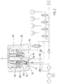
- FIG. 1 shows a level control device in a schematic representation, wherein only the components necessary for the following explanations are shown are.
- the level control device has a compressed air source in the form of a Compressor 2, which is connected to the air springs 6a to 6d via a compressed air line 4 connected is.
- the compressed air line 4 is based on the compressor 2 via an air dryer 8 and an opening to the air springs 6a to 6d Check valve 10 out. Behind the check valve 10 (from the air dryer 8 seen from) branch off the compressed air line 4 compressed air lines 4a to 4d, one of which leads to the air springs 6a to 6d.
- Each compressed air line 4a to 4d contains an electrically controllable 2/2-way valve 12a to 12d, with which the Compressed air lines 4a to 4d can be blocked or switched through.
- the Compressed air line 4 is behind the check valve 10 (from the air dryer 8 seen) additionally with a pressure sensor 14, its function will be explained later.
- a control line 20 branches from the Compressed air line 4, which via an electrically controllable 3/2-way valve 22 the control input 24 of the pneumatically controllable directional valve 26 is guided (The electrically controllable directional valve 22 is in the introduction to the controllable second directional valve; it connects in that in FIG shown basic state the control input with the atmosphere and in other switching state, it switches through the control line 20). Furthermore branches between the check valve 10 and the branch points 16a to 16d a drain line 28 from the compressed air line 4, the first part 28a in an inlet opening 30 of the pneumatically controllable directional valve opens.
- the second part 28b of the discharge line 28 emerges again in the outlet opening 32 pneumatically controllable directional control valve 26.
- the partial line 28b is going out led from the outlet opening 32 at a point 34 to the compressed air line 4, which lies between the air dryer 8 and the check valve 10.
- a further compressed air line 38 from the compressed air line 4 from there is guided to an outlet 40 of the pneumatically controllable directional valve 26.
- the compressed air line 38 connects either the air springs 6a to 6d via the Drain line 28 or the compressor 2 with the atmosphere. Like this happens, is explained in more detail below.
- the pneumatically controllable directional valve 26 has Housing 42 in which a first piston in the form of a preferably rotationally symmetrical stepped piston 44 is arranged.
- the stepped piston 44 is acted upon by a first spring 46 and counter to the restoring force thereof arranged axially movably in the housing 42, being by a Cylinder wall of the housing 42 is guided.
- Below the first stage 48 of the Step piston 44 has an annular space 50 in which the control input 24 of the pneumatically controllable directional valve 26 opens.
- the stepped piston 44 is preferably seated on a seat 54 of the housing 42.
- the housing 42 of the pneumatically controllable directional valve 26 has in addition to the first annulus 50 on another annulus 56 in which both Inlet opening 30 and the outlet opening 32 of the drain line 28 opens.
- the stepped piston 44 projects into the second annular space 56 and seals it Inlet opening 30 and the outlet opening 32 of the drain line 28 with a Ring seal towards the annular space 56 when it is in its seat 54 (as shown in Figure 1).
- the step piston 44 also has a driver 58, the function of which will be explained later.
- the pneumatically controllable directional valve 26 has, in addition to the stepped piston 44 a preferably rotationally symmetrical axially movable second piston 60 on, which is arranged coaxially to and from the stepped piston 44 is included.
- the second piston 60 is through the inner wall of the step piston 44 axially guided and held on a sealing seat 64 by a second spring 62.
- the end face 66 of the second piston 60 blocks the outlet 40 of the pneumatically controllable directional control valve 26 when the second piston 60 is open its sealing seat.
- the second piston 60 is against the Restoring force of the second spring 62 is lifted from its sealing seat, so it gives via a channel 68 which is between the stepped piston 44 and the second Piston 60 is guided, and via an outlet opening 70 in the housing 42 Connection of output 40 to the atmosphere free.
- the second piston 60 lifts off its sealing seat 64 against the restoring force of the second spring 62, so that the compressed air line 38 then passes through the Channel 68 is connected to the atmosphere and the outlet opening 70.
- the compressor 2 then no longer delivers into the air spring 6a, but only into the atmosphere, thereby ensuring that the air spring 6a cannot be filled with compressed air beyond a predetermined air pressure The same applies to the filling of the air springs 6b to 6d.
- the 2/2-way valve 12a is first transferred from the basic state shown in FIG. 1 to its other switching state, so that the compressed air line 4a is switched through.
- the control unit (not shown in FIG. 1) likewise sends a control signal to the control input of the electrically controllable 3/2-way valve 22, so that this likewise occurs from its basic state shown in FIG. 1, in which the control input 24 is connected the atmosphere is connected to its other switching state in which the control line 20th
- compressed air can flow from the air spring 6a through the compressed air line 4a and through the control line 20 via the control input 24 into the first annular space 50.
- the first annular space lies 50 the same air pressure as in the air spring 6a.
- the step piston 44 counteracts the restoring force the first spring 46 is lifted from its seat 54. After lifting takes effect the compressed air in the annular space 50 both on the end face of the first stage 48 and also on the end face of the second step 52 of the first step piston 44, see above that the force acting on the first step piston 44 correspondingly enlarged.
- This force is large enough, also the second piston 60 with the help of the Driver 58 against the restoring force of the second spring 62 of his Lift off sealing seat 64 so that the second piston 60 connects to Atmosphere.
- the stepped piston 44 is removed from the sealing seats of the inlet opening 30 or the outlet opening 32 is lifted, whereby these are opened.
- the first partial line 28a is over with the second partial line 28b the second annulus 56 interconnected.
- the compressed air line 4a From the air spring 6a now through the compressed air line 4a, the first sub-line 28a, through the Annulus 56, through the second sub-line 28b, through the air dryer 8 and through the compressed air line 38 (which in this case is also part of the Drain line is), through the channel 68 and through the outlet opening 70 air into the Stream atmosphere.
- the Control unit the valves 12a and 22 in those shown in Figure 1 Basic state transferred.
- the control input 24 of the pneumatically controllable Directional control valve 26 is then via the 3/2-way valve 22 with the atmosphere connected so that the air pressure located in the first annular space 50 Atmospheric pressure drops.
- the step piston 44 is then by the Restoring force of the first spring 46 on its seat 54 and the second piston 60 is then against the restoring force of the second spring 62 on its sealing seat 64 pressed.
- the connection of the air spring 64 to the atmosphere is then interrupted and the air spring 6a can not be emptied because the Sub-lines 28a and 28b no longer with one another via the second annular space 56 stay in contact.
- the air springs 6b to 6d are emptied accordingly.
- the level control device has the advantage that the total air flow resulting from the individual air flows from the Air springs 6a to 6d composed exclusively via the pneumatic controllable directional valve 26 is guided. Because of this big one Flow cross sections can be switched is a fast Flow through this directional valve 26 is ensured even when several Air springs 6a to 6d are to be emptied simultaneously. So there is also a rapid emptying of several air springs possible at the same time.
- the stepped piston 44 from its seat 54 lift off against the restoring force of the first spring 46.
- the drain line 28 thus remains by the stepped piston 44 of the pneumatically controllable Directional control valve 26 is blocked and no air can flow into the air dryer 8.
- the air pressure measurement with the help of the pressure sensor 14 is therefore not a Outflow of compressed air and an associated drop in pressure in the Air spring 6a adulterated.
- the air pressure in the air springs 6b to 6d can be measured accordingly.
- Figure 2 shows a level control device in a schematic representation, the is largely constructed in exactly the same way as that shown in FIG Level control device.
- the functionality of the in the FIG. 2 shows the level control device with the functionality of that shown in FIG. 1 shown level control device identical, so that in this regard to the Description of the figures is referenced to FIG. 1.
- the extension 76 also lifts from the Sealing seat 64 from and the two sub-lines 28a and 28b are above the Hole 74 in connection. There can then be air from one of the or several air springs of the level control device are released into the atmosphere be (for further details see figure description for Figure 1).
- the base area of the bore is made as small as possible, at least much smaller than the annular area of the annular space 56, in which pneumatically controllable directional valve 26 according to FIG. 1, the openings 30 and 32 flow out. For this reason, the force on the step piston 44 at Flow through the bore 74 is exerted much less than the force is exerted on the stepped piston 44 as it flows through the annular space 56, when air is released from one or more air springs.
- the pneumatically controllable directional control valve 26 shown in FIG. 2 becomes the exact one Control possibility via the control input 24 with the help of the static Air pressure in the air springs is significantly less affected than that in the FIG. 1 shows the pneumatically controllable directional valve 26.
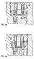
- Figure 3a shows the pneumatically controllable directional control valve shown in Figure 2 26 in the switching state in which there is the compressor with the atmosphere connects (overpressure function).
- Figure 3b shows that shown in Figure 2 pneumatically controllable directional valve 26 in the switching state in which there is a or connects several air springs to the atmosphere for emptying.
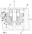
- Figure 4 shows a pneumatically controllable directional valve 26, in which the Sub-lines 28a and 28b of the discharge line 28 through the housing 42 in this way be guided laterally onto the lateral surface of the stepped piston 44 that they are spaced apart in the axial direction of the stepped piston 44 on the Mantle surface open.
- the step piston 44 contains two grooves, each in each There is an O-ring 78a or 78b. If the first step piston 44 on its Seat 54 is seated, the first O-ring 78a is located above the partial line 28b and the second O-ring 78b between the sub-lines 28a and 28b. Every O-ring is between the step piston 44 and the housing wall of the housing 42 radially pressed so that neither air from one sub-line 28a into the other sub-line 28b still air from one of these sub-lines above or below the Stepped piston 44 can reach.
- the O-rings 78a and 78b are carried along so far that the O-ring 78b lies above the partial line 28b.
- the two sub-lines 28a and 28b are then via an annular groove 80 in the lateral surface of the stepped piston 44 with one another connected so that air flows from the partial line 28a into the partial line 28b can and thus one or more of the air springs of the level control device can be connected to the atmosphere (for details see description of figures to Figure 1).
Landscapes
- Engineering & Computer Science (AREA)
- Mechanical Engineering (AREA)
- Vehicle Body Suspensions (AREA)
- Fluid-Damping Devices (AREA)
- Lift Valve (AREA)
- Fluid-Driven Valves (AREA)
- Valves And Accessory Devices For Braking Systems (AREA)
- Fluid-Pressure Circuits (AREA)
Abstract
Description
- die Ablaßleitung getrennt von der Steuerleitung durch das pneumatisch steuerbare erste Wegeventil geführt wird und durch den ersten Kolben gesperrt ist, wenn sich dieser auf seinem Sitz befindet, und geöffnet ist, wenn der erste Kolben von seinem Sitz abgehoben ist, so daß dann Luft aus der Luftfeder in die Atmosphäre abgelassen werden kann.
- das pneumatisch steuerbare erste Wegeventil einen Raum enthält, in den der erste Kolben zumindest teilweise eintaucht, und daß
- die Ablaßleitung zwei Teilleitungen enthält, die jeweils an einem ihrer Enden in den Raum münden, und daß
- zumindest eine der Mündungsöffnungen durch den ersten Kolben verschlossen ist, wenn sich dieser auf seinem Sitz befindet, und beide Mündungsöffnungen geöffnet sind, wenn der erste Kolben von seinem Sitz abgehoben ist, so daß dann die beiden Teilleitungen über dem Raum miteinander verbunden sind.
- die Ablaßleitung zwei Teilleitungen enthält, die in axialer Richtung des Kolbens voneinander beabstandet jeweils an einem ihrer Enden auf der Mantelfläche des ersten Kolbens münden, und daß
- zwischen der Mantelfläche des ersten Kolbens und der Wand eines Gehäuses, in dem der erste Kolben axial geführt wird, eine Dichtung angeordnet ist, die mit dem ersten Kolben derart in Wirkverbindung steht, daß eine Verbindung der Teilleitungen entlang der Mantelfläche des ersten Kolbens gesperrt ist, wenn sich dieser auf seinem Sitz befindet, und die Verbindung freigegeben ist, wenn der erste Kolben von seinem Sitz abgehoben wird.
- Fig. 1
- eine Niveauregeleinrichtung in schematischer Darstellung,
- Fig. 2
- eine Niveauregeleinrichtung in schematischer Darstellung,
- Fig. 3
- ein pneumatisch steuerbares Wegeventil,
- Fig. 4
- ein pneumatisch steuerbares Wegeventil.

- 2
- Kompressor
- 4, 4a - 4d
- Druckluftleitung
- 6a - 6d
- Luftfedern
- 8
- Lufttrockner
- 10
- Rückschlagventil
- 12a - 12d
- 2/2-Wegeventil
- 14
- Drucksensor
- 16a - 16d, 18
- Abzweigungspunkt
- 20
- Steuerleitung
- 22
- 3/2-Wegeventil
- 24
- Steuereingang
- 26
- pneumatisch steuerbares Wegeventil
- 28
- Ablaßleitung
- 28a, b
- Teilleitung der Ablaßleitung
- 30
- Eintrittsöffnung
- 32
- Austrittsöffnung
- 34, 36
- Punkt
- 38
- Druckluftleitung
- 40
- Ausgang
- 42
- Gehäuse
- 44
- Stufenkolben
- 46
- erste Feder
- 48
- erste Stufe
- 50
- Ringraum
- 52
- zweite Stufe
- 54
- Sitz
- 56
- Ringraum
- 58
- Mitnehmer
- 60
- zweiter Kolben
- 62
- zweite Feder
- 64
- Dichtsitz
- 66
- Stirnfläche des zweiten Kolbens
- 68
- Kanal
- 70
- Austrittsöffnung
- 72
- Drossel
- 74
- Bohrung
- 76
- Fortsatz
- 78
- O-Ring
- 80
- Bohrung bzw. Ringnut
- 82
- Ringdichtung
Claims (8)
- Niveauregeleinrichtung für Fahrzeuge mit Luftfedern (6a bis 6d), die folgende Merkmale aufweist:eine Druckluftquelle (2), die zum Auffüllen jeder Luftfeder (6a bis 6d) über einen Lufttrockner (8) mit dieser verbindbar ist und über ein pneumatisch steuerbares erstes Wegeventil (26) mit der Atmosphäre verbindbar ist, wenn ein vorgegebener Förderdruck überschritten wirdjede Luftfeder (6a bis 6d) ist zum Entleeren über eine Ablaßleitung (28), die über das pneumatisch steuerbare erste Wegeventil (26) und über den Lufttrockner (8) geführt wird, mit der Atmosphäre verbindbar, wobei ein pneumatischer Steuereingang (24) des ersten Wegeventils (26) dann über eine Steuerleitung (20), die über ein zwischen den Luftfedern (6a bis 6d) und dem ersten Wegeventil (26) gelegenes steuerbares zweites Wegeventil (22) geführt wird, mit dem Luftdruck einer Luftfeder (6a bis 6d) beaufschlagt ist,
wobei das pneumatisch steuerbare erste Wegeventil (26) folgende Bestandteile enthält:einen ersten Kolben (44), der durch eine erste Feder (46) auf einem Sitz (54) gehalten wird, mit einem Mitnehmer (58), wobei der erste Kolben (44) entgegen der Rückstellkraft der ersten Feder (46) von seinem Sitz (54) abhebt, wenn der pneumatische Steuereingang (24) mit dem Luftdruck einer Luftfeder (6a bis 6d) beaufschlagt wirdeinen zweiten Kolben (60), der durch eine zweite Feder (62) auf einem Dichtsitz (64) gehalten wird und dann eine Verbindung zur Atmosphäre sperrt, und der mit dem ersten Kolben (44) in Wirkverbindung steht, und der eine Stirnfläche (66) aufweist, die mit der Druckluft der Druckluftquelle (2) und der Ablaßleitung (28) beaufschlagbar ist, wobei der zweite Kolben (60) entgegen der Rückstellkraft der zweiten Feder (62) von seinem Dichtsitz (64) entweder durch den Mitnehmer (58) des ersten Kolbens (44), wenn dieser von seinem Sitz (54) abgehoben wird, oder durch die von der Druckluftquelle (2) erzeugte Druckluft, wenn diese den vorgegebenen Förderdruck überschreitet, abgehoben wird und dann mindestens eine Luftfeder (6a bis 6d) bzw. die Druckluftquelle (2) mit der Atmosphäre verbunden ist
dadurch gekennzeichnet, daßdie Ablaßleitung (28) getrennt von der Steuerleitung (20) durch das pneumatisch steuerbare erste Wegeventil (26) geführt wird und durch den ersten Kolben (44) gesperrt ist, wenn sich dieser auf seinem Sitz (54) befindet, und geöffnet ist, wenn der erste Kolben (44) von seinem Sitz (54) abgehoben ist, so daß dann Luft aus einer Luftfeder (6a bis 6d) in die Atmosphäre abgelassen werden kann. - Niveauregeleinrichtung nach Anspruch 1, dadurch gekennzeichnet, daßdas pneumatisch steuerbare erste Wegeventil (26) einen Raum (50, 74) enthält, in den der Kolben (44) zumindest teilweise eintaucht, und daßdie Ablaßleitung (28) zwei Teilleitungen (28a und 28b) enthält, die jeweils an einem ihrer Enden (30, 32) in den Raum (50, 74) münden, und daßzumindest eine der Mündungsöffnungen (30, 32) durch den ersten Kolben (44) verschlossen ist, wenn sich dieser auf seinem Sitz (54) befindet, und beide Mündungsöffnungen (30, 32) geöffnet sind, wenn der erste Kolben (44) von seinem Sitz (54) abgehoben ist, so daß dann die beiden Teilleitungen (28a, 28b) über den Raum (50, 74) miteinander verbunden sind.
- Niveauregeleinrichtung nach Anspruch 2, dadurch gekennzeichnet, daß zumindest eine der Teilleitungen (28a, 28b) in einem Dichtsitz (64) mündet, auf dem der erste Kolben (44) sitzt, und daß der erste Kolben (44) durch die erste Feder (46) auf dem Dichtsitz (64) gehalten wird.
- Niveauregeleinrichtung nach einem der Ansprüche 2 bis 3, dadurch gekennzeichnet, daß es sich bei dem Raum (50, 74) um einen Ringraum (50) oder um eine Bohrung (74) im Gehäuse (42) des pneumatisch steuerbaren ersten Wegeventils (26) handelt.
- Niveauregeleinrichtung nach Anspruch 1, dadurch gekennzeichnet, daßdie Ablaßleitung (28) zwei Teilleitungen (28a, 28b) enthält, die in axialer Richtung des ersten Kolbens (44) voneinander beabstandet jeweils an einem ihrer Enden auf der Mantelfläche des ersten Kolbens (44) münden, und daßzwischen der Mantelfläche des ersten Kolbens (44) und der Wand eines Gehäuses (42), in dem der erste Kolben (44) axial geführt wird, eine Dichtung (78b) angeordnet ist, die mit dem ersten Kolben (44) derart in Wirkverbindung steht, daß eine Verbindung der Teilleitungen (28a, 28b) entlang der Mantelfläche des ersten Kolbens (44) gesperrt ist, wenn sich dieser auf seinem Sitz (54) befindet, und die Verbindung freigegeben ist, wenn der erste Kolben (44) von seinem Sitz (54) abgehoben wird.
- Niveaurregeleinrichtung nach Anspruch 5, dadurch gekennzeichnet, daß der erste Kolben (44) eine Nut enthält, in der ein O-Ring (78b) angeordnet ist, wobei die Nut zwischen den beiden Teilleitungen (28a, 28b) liegt und zwischen dem ersten Kolben (44) und der Zylinderwand radial verpreßt ist, wenn sich der erste Kolben (44) auf seinem Sitz befindet, und oberhalb bzw. unterhalb der beiden Teilleitungen (28a, 28b) liegt, wenn der erste Kolben (44) von seinem Sitz (54) abgehoben wird.
- Niveauregeleinrichtung nach einem der Ansprüche 1 bis 6, dadurch gekennzeichnet, daß die Ablaßleitung (28) eine Drossel (72) enthält, die zwischen den Luftfedern (6a bis 6d) und dem Lufttrockner (8) angeordnet ist.
- Niveauregeleinrichtung nach Anspruch 7, dadurch gekennzeichnet, daß die Drossel (72) in der Ablaßleitung (28) derart angeordnet ist, daß die Luft ausschließlich während des Entleerens einer Luftfeder (6a bis 6d) durch diese strömt.
Applications Claiming Priority (2)
| Application Number | Priority Date | Filing Date | Title |
|---|---|---|---|
| DE19918157 | 1999-04-22 | ||
| DE19918157A DE19918157C1 (de) | 1999-04-22 | 1999-04-22 | Niveauregeleinrichtung für Fahrzeuge mit Luftfedern |
Publications (3)
| Publication Number | Publication Date |
|---|---|
| EP1046521A2 true EP1046521A2 (de) | 2000-10-25 |
| EP1046521A3 EP1046521A3 (de) | 2004-01-14 |
| EP1046521B1 EP1046521B1 (de) | 2008-07-02 |
Family
ID=7905402
Family Applications (1)
| Application Number | Title | Priority Date | Filing Date |
|---|---|---|---|
| EP00107357A Expired - Lifetime EP1046521B1 (de) | 1999-04-22 | 2000-04-05 | Niveauregeleinrichtung für Fahrzeuge mit Luftfedern |
Country Status (4)
| Country | Link |
|---|---|
| US (1) | US6354617B1 (de) |
| EP (1) | EP1046521B1 (de) |
| JP (1) | JP2000326717A (de) |
| DE (2) | DE19918157C1 (de) |
Cited By (2)
| Publication number | Priority date | Publication date | Assignee | Title |
|---|---|---|---|---|
| WO2012079698A1 (de) * | 2010-12-16 | 2012-06-21 | Wabco Gmbh | Druckluftversorgungsanlage, pneumatisches system und verfahren zum betreiben einer pneumatikanlage |
| DE102004036251C5 (de) * | 2004-07-26 | 2018-05-03 | Wabco Gmbh | Verfahren zur Restdruckhaltung in einem Luftfederbalg einer Tragachse |
Families Citing this family (27)
| Publication number | Priority date | Publication date | Assignee | Title |
|---|---|---|---|---|
| DE10004880A1 (de) * | 2000-02-04 | 2001-08-09 | Bayerische Motoren Werke Ag | Luftfedersystem für ein Kraftfahrzeug |
| DE10055108A1 (de) * | 2000-11-07 | 2002-05-08 | Daimler Chrysler Ag | Luftfederung mit geschlossenem Druckluftsystem |
| EP1243447B1 (de) * | 2001-03-24 | 2005-12-21 | Continental Aktiengesellschaft | Geschlossene Niveauregelanlage für Fahrzeuge |
| DE10223405B4 (de) * | 2002-05-25 | 2007-01-11 | Daimlerchrysler Ag | Luftfedersystem für ein Kraftfahrzeug |
| DE10231251C1 (de) * | 2002-07-11 | 2003-08-14 | Continental Ag | Geschlossene Niveauregelanlage mit zwei Druckspeichern für Fahrzeuge |
| DE10240357B4 (de) * | 2002-09-02 | 2016-10-06 | Wabco Gmbh | Luftfederungsanlage für ein Fahrzeug |
| US7240911B1 (en) | 2004-05-19 | 2007-07-10 | Escalante Enterprises, L.L.C. | System for controlling distribution of fluid to a system of air bags for use with vehicular trailers |
| KR100599487B1 (ko) | 2004-09-06 | 2006-07-12 | 현대모비스 주식회사 | 폐루프 차고조절시스템 |
| US20080290617A1 (en) * | 2007-05-22 | 2008-11-27 | Bfs Diversified Products, Llc | Gas suspension system and method |
| KR100881081B1 (ko) * | 2007-10-22 | 2009-01-30 | 현대모비스 주식회사 | 에어 서스펜션 시스템 |
| DE102010020524A1 (de) | 2010-05-14 | 2011-11-17 | Dr. Ing. H.C. F. Porsche Aktiengesellschaft | Restdruckhalteventil und Federbein |
| DE102010020525A1 (de) * | 2010-05-14 | 2011-11-17 | Dr. Ing. H.C. F. Porsche Aktiengesellschaft | Restdruckhalteventil und Federbein |
| DE102010054709A1 (de) | 2010-12-16 | 2012-06-21 | Wabco Gmbh | Lufttrockner-System, Druckluftversorgungsanlage, pneumatisches System und Verfahren zum Betreiben einer Pneumatikanlage |
| DE102010054703B4 (de) * | 2010-12-16 | 2019-12-12 | Wabco Gmbh | Luftfederanlage, pneumatisches System und Fahrzeug mit einer Luftfederanlage und ein Verfahren zum Betrieb einer Pneumatikanlage der Luftfederanlage |
| DE102011083614A1 (de) | 2011-03-01 | 2012-09-06 | Continental Teves Ag & Co. Ohg | Trocknerschaltung für eine pneumatische Regelvorrichtung eines Fahrzeugs |
| DE102012005345B4 (de) | 2011-12-23 | 2024-02-08 | Zf Cv Systems Hannover Gmbh | Druckluftversorgungsanlage, Druckluftversorgungssystem, Fahrzeug und Verwendung der Druckluftversorgungsanlage |
| DE102012001736A1 (de) * | 2012-01-31 | 2013-08-01 | Wabco Gmbh | Druckluftversorgungsanlage, pneumatisches System und Verfahren zum Betreiben einer Druckluftversorgungsanlage bzw. eines pneumatischen Systems |
| DE102012001734B4 (de) * | 2012-01-31 | 2020-11-12 | Wabco Gmbh | Druckluftversorgungsanlage, pneumatisches System und Verfahren zum Betreiben einer Druckluftversorgungsanlage bzw. eines pneumatischen Systems |
| DE102014010956B4 (de) * | 2014-06-25 | 2023-06-15 | Zf Cv Systems Hannover Gmbh | Druckluftversorgungsanlage, pneumatisches System und Verfahren zum Betreiben einer Druckluftversorgungsanlage |
| KR102348626B1 (ko) * | 2014-08-22 | 2022-01-07 | 바브코 게엠베하 | 차량 에어 서스펜션 시스템용 공압 회로 |
| DE102014012645A1 (de) | 2014-08-22 | 2016-02-25 | Wabco Gmbh | Druckluftversorgungsanlage, pneumatisches System und Verfahren zum Betreiben einer Pneumatikanlage |
| CN104228511B (zh) * | 2014-09-04 | 2018-02-16 | 青岛浩釜铭车辆科技有限公司 | 空气弹簧压力平衡阀 |
| JP6475179B2 (ja) | 2016-03-14 | 2019-02-27 | アイシン精機株式会社 | 車高制御システム |
| JP6378228B2 (ja) * | 2016-03-14 | 2018-08-22 | トヨタ自動車株式会社 | 車高調整システム |
| DE102016003661B4 (de) * | 2016-03-30 | 2023-06-29 | Zf Cv Systems Hannover Gmbh | Druckluftversorgungsanlage |
| US11135888B2 (en) | 2019-02-26 | 2021-10-05 | Beijingwest Industries Co., Ltd. | Closed integrated air management module |
| US12552214B1 (en) | 2024-12-13 | 2026-02-17 | Torc Robotics, Inc. | Vehicle air spring system and methods for controlling vehicle stability using air springs |
Family Cites Families (10)
| Publication number | Priority date | Publication date | Assignee | Title |
|---|---|---|---|---|
| US4050746A (en) * | 1975-09-09 | 1977-09-27 | Midland-Ross Corporation | Inversion brake valve and system therefor |
| US4565067A (en) * | 1982-09-30 | 1986-01-21 | Mitsubishi Jidosha Kogyo Kabushiki Kaisha | Brake system for vehicles |
| DE3542974A1 (de) * | 1985-12-05 | 1987-06-11 | Wabco Westinghouse Fahrzeug | Niveauregeleinrichtung fuer fahrzeuge mit luftfedern |
| DE3542975A1 (de) * | 1985-12-05 | 1987-06-11 | Wabco Westinghouse Fahrzeug | Niveauregeleinrichtung fuer fahrzeuge mit luftfedern |
| US5340203A (en) * | 1993-06-11 | 1994-08-23 | Westinghouse Air Brake Company | Variable load control valve with dual diaphragms reinforced by washers and spacer members |
| US5409303A (en) * | 1994-06-02 | 1995-04-25 | Midland Brake, Inc. | Full function skid control braking system for vehicles |
| US5458403A (en) * | 1994-04-29 | 1995-10-17 | Midland Brake, Inc. | Full-function valve with quick drive away for heavy duty semi-trailer brake systems |
| US5738416A (en) * | 1994-07-22 | 1998-04-14 | Westinghouse Air Brake Company | Railway braking apparatus to effect a change in a handbrake |
| US6012482A (en) * | 1997-01-30 | 2000-01-11 | Djt Products, Inc. | Line break detector for pressurized fluid pumping systems |
| DE19745195C2 (de) * | 1997-10-13 | 2000-11-02 | Continental Ag | Niveauregeleinrichtung für Fahrzeuge mit Luftfedern |
-
1999
- 1999-04-22 DE DE19918157A patent/DE19918157C1/de not_active Expired - Fee Related
-
2000
- 2000-04-05 EP EP00107357A patent/EP1046521B1/de not_active Expired - Lifetime
- 2000-04-05 DE DE50015230T patent/DE50015230D1/de not_active Expired - Fee Related
- 2000-04-21 JP JP2000121028A patent/JP2000326717A/ja not_active Withdrawn
- 2000-04-24 US US09/556,428 patent/US6354617B1/en not_active Expired - Fee Related
Non-Patent Citations (1)
| Title |
|---|
| None |
Cited By (2)
| Publication number | Priority date | Publication date | Assignee | Title |
|---|---|---|---|---|
| DE102004036251C5 (de) * | 2004-07-26 | 2018-05-03 | Wabco Gmbh | Verfahren zur Restdruckhaltung in einem Luftfederbalg einer Tragachse |
| WO2012079698A1 (de) * | 2010-12-16 | 2012-06-21 | Wabco Gmbh | Druckluftversorgungsanlage, pneumatisches system und verfahren zum betreiben einer pneumatikanlage |
Also Published As
| Publication number | Publication date |
|---|---|
| JP2000326717A (ja) | 2000-11-28 |
| US6354617B1 (en) | 2002-03-12 |
| EP1046521A3 (de) | 2004-01-14 |
| EP1046521B1 (de) | 2008-07-02 |
| DE50015230D1 (de) | 2008-08-14 |
| DE19918157C1 (de) | 2000-10-26 |
Similar Documents
| Publication | Publication Date | Title |
|---|---|---|
| DE19918157C1 (de) | Niveauregeleinrichtung für Fahrzeuge mit Luftfedern | |
| EP0818629B1 (de) | Hydraulische Stelleinheit und Verfahren zum Entlüften einer hydraulischen Stelleinheit | |
| DE69727307T2 (de) | Vorrichtung zum Halten des Schaftes eines Hydraulikzylinders in Stellung | |
| DE19745195C2 (de) | Niveauregeleinrichtung für Fahrzeuge mit Luftfedern | |
| DE19953075B4 (de) | Stellgliedsteuerschaltkreis | |
| EP3402705B1 (de) | Steuerventileinrichtung für eine elektrische parkbremsvorrichtung und elektrische parkbremsvorrichtung | |
| CH670483A5 (de) | ||
| DE69726199T2 (de) | Ventil mit sich kreuzenden Leitungen und mit Sperrfunktion | |
| EP0353782A1 (de) | Innenmischer | |
| EP0387495B1 (de) | Einrichtung zur Änderung des Druckes im Reifen eines Fahrzeuges | |
| DE2456074B2 (de) | Lastabhaengig gesteuertes relaisventil fuer eine fahrzeug-druckluftbremse | |
| EP3436294B1 (de) | Druckluftversorgungsanlage | |
| DE3246769C2 (de) | ||
| DE3405111C2 (de) | Einrichtung zur Änderung des Druckes in den Reifen eines Fahrzeuges | |
| DE69401196T2 (de) | Abblasventil für ein dampfgefäss | |
| DE3147030C2 (de) | Magnetventileinheit | |
| DE3871680T2 (de) | Ventileinheit, insbesondere zur verwendung im pneumatischen bremssystem eines zugfahrzeugs zur steuerung der bremsen eines anhaengers. | |
| DE19647763C2 (de) | Einrichtung zur Steuerung des Geradlaufes eines endlosen Bandes | |
| EP1647473A1 (de) | Anlage für Kraftfahrzeuge mit Luftfederung und Liftachse | |
| AT404065B (de) | Startventil für pneumatische anlagen | |
| EP0026504B1 (de) | Absenkeinrichtung einer Führerbremsventilanlage für indirekt wirkende Druckluftbremsen von Schienenfahrzeugen | |
| DE19944808C1 (de) | Druckbegrenzungs- und Drucksicherungsventil für Druckluftbremsanlagen von Kraftfahrzeugen | |
| EP0659622A1 (de) | Druckluftbetätigte Zweileitungs-Bremsanlage | |
| DE19545640B4 (de) | Steuerventileinrichtung | |
| DE600986C (de) | Druckluftbremseinrichtung |
Legal Events
| Date | Code | Title | Description |
|---|---|---|---|
| PUAI | Public reference made under article 153(3) epc to a published international application that has entered the european phase |
Free format text: ORIGINAL CODE: 0009012 |
|
| AK | Designated contracting states |
Kind code of ref document: A2 Designated state(s): AT BE CH CY DE DK ES FI FR GB GR IE IT LI LU MC NL PT SE |
|
| AX | Request for extension of the european patent |
Free format text: AL;LT;LV;MK;RO;SI |
|
| PUAL | Search report despatched |
Free format text: ORIGINAL CODE: 0009013 |
|
| AK | Designated contracting states |
Kind code of ref document: A3 Designated state(s): AT BE CH CY DE DK ES FI FR GB GR IE IT LI LU MC NL PT SE |
|
| AX | Request for extension of the european patent |
Extension state: AL LT LV MK RO SI |
|
| RIC1 | Information provided on ipc code assigned before grant |
Ipc: 7B 60G 17/015 B Ipc: 7B 60G 17/052 A |
|
| 17P | Request for examination filed |
Effective date: 20040714 |
|
| AKX | Designation fees paid |
Designated state(s): DE ES FR IT |
|
| GRAP | Despatch of communication of intention to grant a patent |
Free format text: ORIGINAL CODE: EPIDOSNIGR1 |
|
| GRAS | Grant fee paid |
Free format text: ORIGINAL CODE: EPIDOSNIGR3 |
|
| GRAA | (expected) grant |
Free format text: ORIGINAL CODE: 0009210 |
|
| AK | Designated contracting states |
Kind code of ref document: B1 Designated state(s): DE ES FR IT |
|
| REF | Corresponds to: |
Ref document number: 50015230 Country of ref document: DE Date of ref document: 20080814 Kind code of ref document: P |
|
| PG25 | Lapsed in a contracting state [announced via postgrant information from national office to epo] |
Ref country code: ES Free format text: LAPSE BECAUSE OF FAILURE TO SUBMIT A TRANSLATION OF THE DESCRIPTION OR TO PAY THE FEE WITHIN THE PRESCRIBED TIME-LIMIT Effective date: 20081013 |
|
| PLBE | No opposition filed within time limit |
Free format text: ORIGINAL CODE: 0009261 |
|
| STAA | Information on the status of an ep patent application or granted ep patent |
Free format text: STATUS: NO OPPOSITION FILED WITHIN TIME LIMIT |
|
| 26N | No opposition filed |
Effective date: 20090403 |
|
| PG25 | Lapsed in a contracting state [announced via postgrant information from national office to epo] |
Ref country code: IT Free format text: LAPSE BECAUSE OF FAILURE TO SUBMIT A TRANSLATION OF THE DESCRIPTION OR TO PAY THE FEE WITHIN THE PRESCRIBED TIME-LIMIT Effective date: 20080702 |
|
| REG | Reference to a national code |
Ref country code: FR Ref legal event code: ST Effective date: 20091231 |
|
| PGFP | Annual fee paid to national office [announced via postgrant information from national office to epo] |
Ref country code: DE Payment date: 20090925 Year of fee payment: 10 |
|
| PG25 | Lapsed in a contracting state [announced via postgrant information from national office to epo] |
Ref country code: FR Free format text: LAPSE BECAUSE OF NON-PAYMENT OF DUE FEES Effective date: 20091222 |
|
| PG25 | Lapsed in a contracting state [announced via postgrant information from national office to epo] |
Ref country code: DE Free format text: LAPSE BECAUSE OF NON-PAYMENT OF DUE FEES Effective date: 20101103 |