EP1045499A1 - Pince - Google Patents
Pince Download PDFInfo
- Publication number
- EP1045499A1 EP1045499A1 EP00108282A EP00108282A EP1045499A1 EP 1045499 A1 EP1045499 A1 EP 1045499A1 EP 00108282 A EP00108282 A EP 00108282A EP 00108282 A EP00108282 A EP 00108282A EP 1045499 A1 EP1045499 A1 EP 1045499A1
- Authority
- EP
- European Patent Office
- Prior art keywords
- pliers
- pliers according
- work
- stripping
- jaw
- Prior art date
- Legal status (The legal status is an assumption and is not a legal conclusion. Google has not performed a legal analysis and makes no representation as to the accuracy of the status listed.)
- Withdrawn
Links
Images


Classifications
-
- H—ELECTRICITY
- H02—GENERATION; CONVERSION OR DISTRIBUTION OF ELECTRIC POWER
- H02G—INSTALLATION OF ELECTRIC CABLES OR LINES, OR OF COMBINED OPTICAL AND ELECTRIC CABLES OR LINES
- H02G1/00—Methods or apparatus specially adapted for installing, maintaining, repairing or dismantling electric cables or lines
- H02G1/12—Methods or apparatus specially adapted for installing, maintaining, repairing or dismantling electric cables or lines for removing insulation or armouring from cables, e.g. from the end thereof
- H02G1/1295—Devices for splitting and dismantling flat cables
Definitions
- the invention relates generally to pliers for machining Objects, and in particular on pliers for processing strand-like good.
- Pliers of this type are already generally known. They usually point out a first handle and a second handle, for example are pivotable relative to one another about a common axis, and also have a first work jaw and a second work jaw, the corresponding to each other when pivoting the handles are movable towards or away from each other.
- the invention has for its object a pair of pliers of the aforementioned To create a way with which in particular flat-band-like goods can be edited precisely, and which is also extremely simple Has structure and is cheap to manufacture.
- a pair of pliers according to the invention is characterized in that a respective the work jaws on both the first and second handles is mounted that both work jaws at each pivoting position Handles are parallel to each other.
- this Flat ribbon-like goods for example an electrical flat cable
- the pliers according to the invention can this with the help of the pliers according to the invention, for example, more uniformly cut or stripped more evenly. Even a more even one Crimping over the width of the flat cable is possible.
- the handles in their shape or geometry are identical.
- the work jaws can also have an identical shape or geometry. Molded parts or work programs for the manufacture of the respective handles or work jaws can thus be used for both of the respective elements, which is particularly advantageous and further reduces production costs. This principle can of course also be applied to such pliers, at which do not depend on a parallel position of the two work jaws.
- the holder devices provided for the respective work jaws for holding processing elements in their shape or geometry train identically, for example at a stripping station in the pliers mouth is thought, for example, of four identically constructed assemblies can exist with which processing elements can be connected, for example Stripping knife or clamping bar, or the like.
- the respective ones preferably have Handles the common axis towards the front end of the pliers outstanding and pointing to the other handle Bearing section, each of the work jaws on one such Bearing section and on the other handle in one area, the side of the bearing section facing the rear end of the pliers lies.
- the respective work jaw is pivotally mounted on the bearing section and slidably mounted on the other handle.
- the respective storage section can be swiveled to mount the work jaw carry a bearing axis perpendicular to the pliers plane, while for the sliding displaceability of the respective work jaw of the called other handle at least perpendicular to the plane of the pliers extending lugs, which run in longitudinal grooves, which on the inside of the other side of the working jaws of the work jaw are located.
- the parallel displacement of the work jaws can be done in a simple manner towards each other or away from each other in every pivoting position ensure the handles.
- the longitudinal grooves can also run in plates, the inside of the Rare walls of the work jaws are attached, so that an adjustment or adjustment of the longitudinal grooves after installing the pliers more exact positioning of the plates is possible.
- the work jaws are in the front Pliers area on opposite sections machining tools, about one cutting knife each to form a Cutting station, crimp stamp and die to form a crimp station or at least stripping knife to form a stripping station.
- Other tools would also be conceivable, such as electrically heated devices to carry out heating or melting processes flat ribbon-like goods, and the like.
- each work jaw has two stripping knives running parallel to each other wear, the knife edges of each other when loaded remove. This means that the Push off part of a conductor insulation from the conductor at least in part, what later is the complete acceptance of the separated part greatly facilitated by the leader.
- the stripping station can be formed each work jaw only one stripping knife and one in parallel wear the lying clamps in such a way that the clamps of the two work jaws face each other, one per work jaw existing knife edge of the stripping knife and one Remove the clamping surface of the clamping bar from each other when loaded. This also results in the stripping process of a separated part of the conductor insulation supported by a leader.
- Advantageous in this configuration is moreover that no more two cutting knives per work jaw need to be exactly aligned to make double cuts to avoid.
- the stripping knives or clamping jaws are preferably one at a time tilt axis parallel to them rotatably mounted or, alternatively, each held removably in a holding block, the holding blocks each by one parallel to the stripping knife or clamping bar extending tilt axis are rotatably mounted. This allows you to simple elements such as stripping knives per working jaw and remove the clamping bar from each other.
- the tilting axes are in the longitudinal direction of the pliers in front of and behind Areas of the working jaws.
- the stripping blades, Clamping bars or holding blocks, on which now the machined strand-like estates no longer act, back into their Starting position are brought.
- Springs can be used for this, which push the respective elements back into their starting position.
- a positioning pin can engage between them, which is firmly attached to the respective Work jaws is mounted. The springs then become the respective After pressing elements back against the positioning pin a stripping process has taken place, so that the elements mentioned are then automatically back in their starting position.
- FIG. 1 shows a pair of pliers according to the invention in a perspective view 1 with open jaws.
- the pliers 1 have a first handle 2 and a second handle 3 on. Both handles 2 and 3 are common in their front area Axis 4 can be pivoted relative to one another. In her the common Axis 4 projecting towards the front end of the pliers the handles 2 and 3 each have a bearing section 5, 6 which to the other of the handles. In other words, stretches the bearing section 5 of the first handle 2 a little in the direction to the second handle 3, while the bearing section 6 of the second Handle 3 extends a little towards the first handle 2. in the Area of these bearing sections 5 and 6 carry the handles 2 and 3, respectively a bearing axis 7, 8. This is perpendicular to the pliers plane, the is spanned by the handles 2 and 3.
- a working jaw is pivotally mounted on the bearing axles 7, 8.
- a first work jaw 9 is mounted on the bearing axis 8 while a second work jaw 10 is mounted on the bearing axis 7.
- Both Working jaws 9, 10 are half-shell-shaped and take both Bearing sections 5, 6 between the rare walls 9a belonging to them or 10a, 10b. These side walls 9a and 10a, 10b extend continue towards the rear end of the pliers and grip the one above and areas lying below the common bearing axis 4 of the first and second handles 2 and 3 respectively. So during the first work jaw 9 can be pivoted via the bearing axis 8 on the second handle 3 is stored, it is still in the rear area on the first handle 2 slidably mounted, as later with reference is explained on Figure 2.
- the second work jaw 10 is over the bearing axis 7 on the first handle 2 pivotally while he in its area facing the rear end of the pliers on the second handle 3 is slidably mounted, as also still executed becomes. If the handles 2 and 3 are pivoted, on the one hand the work jaws 9 and 10 corresponding to each other or from each other moved away while on the other hand at each pivot position the handles 2 and 3 the work jaws 9 and 10 parallel to each other come to lie. A rotation or tilting of the work jaws 9 and 10 relative to each other does not take place.
- a stripping station 11 Located in the area of the pliers jaw lying at the front end of the pliers 1 in the present embodiment between the work jaws 9 and 10 a stripping station 11. Belong to this stripping station four holding blocks 12, 13, 14 and 15, two of which are each on one of the Working jaws 9, 10 are rotatably mounted. The on the respective work jaw 9, 10 rotatably mounted holding blocks 12, 13 and 14, 15 are elongated executed and extend in the longitudinal direction of the pliers.
- everyone who Holding blocks 12 to 15 receive a stripping knife 16, 17 or 18, 19, which are parallel to each other and also in the longitudinal direction of the pliers extend.
- the stripping knives 17 and 19 can be seen in FIG. 5.
- the stripping blades 16 and 17 or 18 and 19 are in the starting position the pliers 1 close to each other with the jaws open, while the stripping blades belonging to different working jaws 9 and 10 16, 18 and 17, 19 face each other. They are according to the Conductor structure of a flat cable to be stripped in its cutting area profiled.
- Parallel to the holding blocks 12, 13 in the first work jaw 9 and parallel to the holding blocks 14, 15 in the second work jaw 10 are inside the work jaws tilt axes 20, 21 or 22, 23, around which the respective Holding blocks 12, 13, 14 and 15 are tiltable or pivotable.
- in the 1 is the holding block 12 about the tilt axis 21 in FIG Swiveling clockwise, while the holding block 13 about the tilt axis 20 is pivotable counterclockwise.
- the holding block 14 can be pivoted counterclockwise about the tilt axis 23, while the holding block 15 can be pivoted clockwise about the tilt axis 22 is.
- the tilt axes 20 to 23 are each on a front End face of the work jaws 9 and 10 attached and in the middle Area that is not shown in detail.
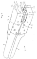
- FIG. 2 shows the pliers according to the invention with the first removed Working jaws 9.
- the attachment can be done, for example, that through the openings 26, 27 in FIG. 1, screws are passed through the side walls 9a, 9b and screwed into threaded holes 28, 29 which are in the guide plates 24, 25 are.
- Each of the guide plates 24, 25 also has a guide groove 30, in which a guide axis 31 engages, which is perpendicular to the plane of the pliers stands and is attached to the first handle 2 or penetrates it.
- the guide groove 30 runs in Figure 2 backwards and obliquely above and allows the work jaw 9 to close itself when the handles are closed 2, 3 due to the movement of the bearing axis 8 also forward to move forward. Since at the same time the bearing axis 8 also moves downwards is, due to the inclination of the groove 30, the rear part of the Work jaws 9 down so that it is always parallel to the second Work jaw 10 remains, in which this guiding principle also is applied.
- the dashed representation of a referenced corresponding guide plate 32 with guide groove 33 which opens towards the rear end of the pliers towards the bottom left in Figure 2.
- a guide axis 34 which is on the second Handle 3 is attached or penetrates it.
- the attachment of the guide plate 32 on the inside of the side wall 10a takes place in the same Way as the attachment of the guide plate 24.
- a corresponding and here not recognizable guide plate is on the opposite inside of the side wall 10b of the second work jaw 10th
- Figure 2 also allows the structure of the upper part of the stripping station 11 in detail.
- the two holding blocks 12, 13 and the ones assigned to them can be seen Tilt axes 20, 21.
- the holding block 12 is about the tilt axis 21 pivotable, for which purpose it has two brackets 37, 38 spaced apart from one another has that protrude laterally beyond it and encompass the tilt axis 21.
- the brackets 37, 38 are integral with the holding block on the upper edge 12 connected and angled so that it over the second holding block 13 run away.
- the tilt axis 21 lies on the holding block 12 opposite side of the holding block 13.
- the holding block 13 also has two brackets 39 and 40 connected to it on its upper side, which are angled to the left in the present case and the tilt axis 20 reach around.
- the brackets 39 and 40 run over the holding block 12.
- the tilt axis 20 lies on the side facing away from the holding block 13 of the holding block 12.
- Both the upper assembly and the lower assembly of the stripping station 11 can be identical, what shape or geometry concerns. Of these, only those carried by the holding blocks can be used Elements make an exception, in this case the stripping knife 16 to 19. They are made with the help of pins or screws Push through the holding blocks, attached to them. The pins or screws bear the common reference number 41 here.
- the pliers are in the position shown in FIG. 2, that is it Pliers mouth open, so the upper holding blocks 12, 13 are spaced to the lower holding blocks 14, 15.
- the holding blocks are located 12, 13 close to each other and also the holding blocks 14 and 15, which means that the stripping knives 16 and 17 lie close together and also the stripping knife 18 and 19, each around a common cutting edge to build. So that the holding blocks 12, 13 on the one hand and the holding blocks 14, 15, on the other hand, can lie closely against one another or against one another are pressed, there are blind holes in the brackets 38 and 39 45, 44 for receiving compression springs, which are not shown here.
- the respective Stripping knives 16 to 19 can also be adjusted to adjust about an axis or to be able to twist, which is perpendicular to the plane of the pliers. Thereby could result in incorrect parallelization of the work jaws due to material elasticity be balanced when operating the pliers.
- each of the holding blocks is a stripping knife must record.
- the holding blocks 12 and 14 it would be possible to use only the holding blocks 12 and 14 to be equipped with stripping knives, while in the Holding blocks 13 and 15 clamping bars (not shown) are positioned, the only for holding or clamping a conductor in the pliers mouth serve. Cutting a conductor insulation would then be the stripping knives 16 and 18 are adopted.
- FIG. 3 shows the pliers 1 according to the invention in the closed position.
- handles 2 and 3 are pressed together and the work jaws 9 and 10 so far parallel to each other that the holding blocks 12, 13, 14 and 15 are pivoted out of their rest position.
- the holding blocks 12, 14 on the one hand and 13, 15 on the other hand respectively with their end edges facing each other and as a result have tilted.
- Figure 4 shows the pliers 1 in the closed state with the removed first work jaws 9.
- the bearing axis moves 8 counterclockwise around the common axis 4 while the bearing axis 7 rotates clockwise around the common axis 4.
- the work jaws 9, 10 are thereby moved towards the end of the tongs and separated from each other, due to the movement of the bearing axes 7, 8 and due to the leadership of the guide axis 31 in the Guide groove 30 and the guide of the guide axis 34 in the guide groove 33.
- FIG. 5 shows a flat cable lying inside the stripping station 11 46, with the remaining parts of the pliers omitted for the sake of clarity are.
- the pliers mouth is closed here and it is the stripping knife 16, 17 and 18, 19 tilted about their respective axes 20, 21, 22 and 23.
- This tipping process can result in a severed insulation end Not only can they be deported, but they also cannot be completely severed smaller areas of the conductor insulation.
- the pliers are therefore particularly simple and inexpensive to manufacture.
Landscapes
- Gripping Jigs, Holding Jigs, And Positioning Jigs (AREA)
Applications Claiming Priority (2)
| Application Number | Priority Date | Filing Date | Title |
|---|---|---|---|
| DE29906890U DE29906890U1 (de) | 1999-04-16 | 1999-04-16 | Zange |
| DE29906890U | 1999-04-16 |
Publications (1)
| Publication Number | Publication Date |
|---|---|
| EP1045499A1 true EP1045499A1 (fr) | 2000-10-18 |
Family
ID=8072372
Family Applications (1)
| Application Number | Title | Priority Date | Filing Date |
|---|---|---|---|
| EP00108282A Withdrawn EP1045499A1 (fr) | 1999-04-16 | 2000-04-14 | Pince |
Country Status (2)
| Country | Link |
|---|---|
| EP (1) | EP1045499A1 (fr) |
| DE (1) | DE29906890U1 (fr) |
Cited By (4)
| Publication number | Priority date | Publication date | Assignee | Title |
|---|---|---|---|---|
| WO2003100934A1 (fr) * | 2002-05-28 | 2003-12-04 | Krampe Kg | Outil de denudage |
| EP1630918A1 (fr) * | 2004-08-27 | 2006-03-01 | Nexans | Appareil pour le montage d'un câble de transmission de données sur une pièce d'équipement |
| US7104815B2 (en) | 2003-04-29 | 2006-09-12 | Wing Hok Ng | Receptacle for booster cable with clamp |
| GB2602820A (en) * | 2021-01-15 | 2022-07-20 | Michael Agnew David | An accessory for a cable dismantling tool |
Families Citing this family (2)
| Publication number | Priority date | Publication date | Assignee | Title |
|---|---|---|---|---|
| DE50006085D1 (de) * | 2000-10-16 | 2004-05-19 | Weidmueller Interface | Abisolierwerkzeug |
| DE202004014801U1 (de) * | 2004-02-02 | 2005-06-09 | Weidmüller Interface GmbH & Co. KG | Abisolierzange |
Citations (3)
| Publication number | Priority date | Publication date | Assignee | Title |
|---|---|---|---|---|
| US649039A (en) * | 1899-08-04 | 1900-05-08 | William Schollhorn Co | Pliers. |
| US4112791A (en) * | 1975-11-11 | 1978-09-12 | C. A. Weidmuller Kg | Cable-stripping tool |
| EP0303889A2 (fr) * | 1987-08-15 | 1989-02-22 | Weitkowitz Elektro Gmbh | Pince à entailler pour sertir des embouts d'extrémité, des souliers de câble et des connecteurs aux conducteurs électriques |
-
1999
- 1999-04-16 DE DE29906890U patent/DE29906890U1/de not_active Expired - Lifetime
-
2000
- 2000-04-14 EP EP00108282A patent/EP1045499A1/fr not_active Withdrawn
Patent Citations (3)
| Publication number | Priority date | Publication date | Assignee | Title |
|---|---|---|---|---|
| US649039A (en) * | 1899-08-04 | 1900-05-08 | William Schollhorn Co | Pliers. |
| US4112791A (en) * | 1975-11-11 | 1978-09-12 | C. A. Weidmuller Kg | Cable-stripping tool |
| EP0303889A2 (fr) * | 1987-08-15 | 1989-02-22 | Weitkowitz Elektro Gmbh | Pince à entailler pour sertir des embouts d'extrémité, des souliers de câble et des connecteurs aux conducteurs électriques |
Cited By (5)
| Publication number | Priority date | Publication date | Assignee | Title |
|---|---|---|---|---|
| WO2003100934A1 (fr) * | 2002-05-28 | 2003-12-04 | Krampe Kg | Outil de denudage |
| US7104815B2 (en) | 2003-04-29 | 2006-09-12 | Wing Hok Ng | Receptacle for booster cable with clamp |
| EP1630918A1 (fr) * | 2004-08-27 | 2006-03-01 | Nexans | Appareil pour le montage d'un câble de transmission de données sur une pièce d'équipement |
| FR2874755A1 (fr) * | 2004-08-27 | 2006-03-03 | Nexans Sa | Appareil pour le montage d'un cable de transmission de donnees sur une piece d'equipement |
| GB2602820A (en) * | 2021-01-15 | 2022-07-20 | Michael Agnew David | An accessory for a cable dismantling tool |
Also Published As
| Publication number | Publication date |
|---|---|
| DE29906890U1 (de) | 1999-07-15 |
Similar Documents
| Publication | Publication Date | Title |
|---|---|---|
| DE3109289C2 (fr) | ||
| DE1777348C3 (de) | Wechselvorrichtung für eine das obere bewegbare Stanzwerkzeug aufnehmende Werkzeugunterstützung einer Stanzpresse | |
| EP0468335B1 (fr) | Outil pour le sertissage d'un connecteur à un conducteur et une isolation | |
| EP0540880B1 (fr) | Pince de sertissage pour extrémités de fils | |
| EP1557920B1 (fr) | Pince à dénuder avec adaptation automatique à des sections transversales différentes. | |
| DE2018901B2 (de) | Werkzeug zum Andrücken eines im Querschnitt im wesentlichen U-förmigen elektrischen Verbinders an einen Leiter | |
| DE2548771B2 (de) | Vorschub- und Spanneinrichtung für eine Trennmaschine | |
| EP0445406B1 (fr) | Dispositif de serrage horizontal des pièces sur une table d'une scie verticale | |
| DE19818482C1 (de) | Handpreßzange zum Verpressen von Aderendhülsen | |
| EP0562229B1 (fr) | Pince de sertissage pour extrémités des fils | |
| EP0687049A2 (fr) | Dispositif à dénuder | |
| DE2416781C3 (de) | Abisolierzange | |
| DE2432670A1 (de) | Vorrichtung zum trennen von elektrischen verbindern von tragstreifen und zum andruecken derselben an draehte | |
| DE2411744A1 (de) | Presse zum pressverbinden eines mindestens teilweise drahtfoermigen teiles mit einem abschlussteil | |
| EP0735638B1 (fr) | Pince à dénuder | |
| EP1045499A1 (fr) | Pince | |
| EP1080844B1 (fr) | Pince | |
| EP1055487A1 (fr) | Pince avec machoires paralleles | |
| DE2113107A1 (de) | Vorrichtung zum Durchschneiden und teilweisen Abisolieren elektrischer Draehte oder Kabel | |
| DE3347920C2 (de) | Sägeeinrichtung | |
| EP1199780B1 (fr) | Outil de dénudage | |
| DE1925695C3 (de) | Manuell betätigbares Werkzeug zum Biegen und Schneiden von Stäben und Drähten | |
| DE19511372A1 (de) | Kombinierte Abisolier-/Crimpvorrichtung | |
| EP0058349A2 (fr) | Outil pour déformer, presser ou pour exécuter d'autres opérations sous l'application de pression | |
| EP1377395B1 (fr) | Machine de pliage, en particulier presse a estamper ou a plier, pourvue d'un outil inferieur reglable |
Legal Events
| Date | Code | Title | Description |
|---|---|---|---|
| PUAI | Public reference made under article 153(3) epc to a published international application that has entered the european phase |
Free format text: ORIGINAL CODE: 0009012 |
|
| AK | Designated contracting states |
Kind code of ref document: A1 Designated state(s): AT BE CH CY DE DK ES FI FR GB GR IE IT LI LU MC NL PT SE |
|
| AX | Request for extension of the european patent |
Free format text: AL;LT;LV;MK;RO;SI |
|
| 17P | Request for examination filed |
Effective date: 20000921 |
|
| AKX | Designation fees paid |
Free format text: AT BE CH CY DE DK ES FI FR GB GR IE IT LI LU MC NL PT SE |
|
| RAP1 | Party data changed (applicant data changed or rights of an application transferred) |
Owner name: WEIDMUELLER INTERFACE GMBH & CO. |
|
| 17Q | First examination report despatched |
Effective date: 20030905 |
|
| STAA | Information on the status of an ep patent application or granted ep patent |
Free format text: STATUS: THE APPLICATION IS DEEMED TO BE WITHDRAWN |
|
| 18D | Application deemed to be withdrawn |
Effective date: 20040316 |