EP1044762A2 - Verfahren zum Abführen von Zerspanungsprodukten eines zerspanenden Bearbeitungsverfahrens - Google Patents
Verfahren zum Abführen von Zerspanungsprodukten eines zerspanenden Bearbeitungsverfahrens Download PDFInfo
- Publication number
- EP1044762A2 EP1044762A2 EP00105826A EP00105826A EP1044762A2 EP 1044762 A2 EP1044762 A2 EP 1044762A2 EP 00105826 A EP00105826 A EP 00105826A EP 00105826 A EP00105826 A EP 00105826A EP 1044762 A2 EP1044762 A2 EP 1044762A2
- Authority
- EP
- European Patent Office
- Prior art keywords
- machining
- particles
- workpiece
- products
- tool
- Prior art date
- Legal status (The legal status is an assumption and is not a legal conclusion. Google has not performed a legal analysis and makes no representation as to the accuracy of the status listed.)
- Withdrawn
Links
- 238000003754 machining Methods 0.000 title claims abstract description 60
- 238000000034 method Methods 0.000 title claims abstract description 30
- 239000002245 particle Substances 0.000 claims abstract description 63
- 238000005520 cutting process Methods 0.000 claims abstract description 27
- 238000012545 processing Methods 0.000 claims abstract description 13
- 239000007787 solid Substances 0.000 claims abstract description 10
- 239000007789 gas Substances 0.000 claims description 37
- 238000001816 cooling Methods 0.000 claims description 11
- 238000005461 lubrication Methods 0.000 claims description 9
- 239000000314 lubricant Substances 0.000 claims description 7
- IJGRMHOSHXDMSA-UHFFFAOYSA-N Atomic nitrogen Chemical compound N#N IJGRMHOSHXDMSA-UHFFFAOYSA-N 0.000 claims description 6
- 239000000428 dust Substances 0.000 claims description 5
- XAGFODPZIPBFFR-UHFFFAOYSA-N aluminium Chemical compound [Al] XAGFODPZIPBFFR-UHFFFAOYSA-N 0.000 claims description 3
- 239000011261 inert gas Substances 0.000 claims description 3
- 238000003801 milling Methods 0.000 claims description 3
- 229910052757 nitrogen Inorganic materials 0.000 claims description 3
- FYYHWMGAXLPEAU-UHFFFAOYSA-N Magnesium Chemical compound [Mg] FYYHWMGAXLPEAU-UHFFFAOYSA-N 0.000 claims description 2
- 229910052782 aluminium Inorganic materials 0.000 claims description 2
- 238000005553 drilling Methods 0.000 claims description 2
- 229910052749 magnesium Inorganic materials 0.000 claims description 2
- 239000011777 magnesium Substances 0.000 claims description 2
- 238000007514 turning Methods 0.000 claims description 2
- 229910000838 Al alloy Inorganic materials 0.000 claims 1
- 229910000861 Mg alloy Inorganic materials 0.000 claims 1
- 238000003672 processing method Methods 0.000 claims 1
- CURLTUGMZLYLDI-UHFFFAOYSA-N Carbon dioxide Chemical compound O=C=O CURLTUGMZLYLDI-UHFFFAOYSA-N 0.000 description 48
- 229910002092 carbon dioxide Inorganic materials 0.000 description 23
- 239000001569 carbon dioxide Substances 0.000 description 23
- 239000007788 liquid Substances 0.000 description 7
- 239000002826 coolant Substances 0.000 description 6
- 230000000694 effects Effects 0.000 description 3
- 239000000463 material Substances 0.000 description 3
- 235000011089 carbon dioxide Nutrition 0.000 description 2
- 238000004140 cleaning Methods 0.000 description 2
- 239000005068 cooling lubricant Substances 0.000 description 2
- 238000009826 distribution Methods 0.000 description 2
- 238000001704 evaporation Methods 0.000 description 2
- 239000002360 explosive Substances 0.000 description 2
- 238000000605 extraction Methods 0.000 description 2
- 238000004519 manufacturing process Methods 0.000 description 2
- 238000012958 reprocessing Methods 0.000 description 2
- 241000589614 Pseudomonas stutzeri Species 0.000 description 1
- 239000000956 alloy Substances 0.000 description 1
- 229910045601 alloy Inorganic materials 0.000 description 1
- 230000015572 biosynthetic process Effects 0.000 description 1
- 239000000356 contaminant Substances 0.000 description 1
- 238000005516 engineering process Methods 0.000 description 1
- 230000008020 evaporation Effects 0.000 description 1
- 238000004880 explosion Methods 0.000 description 1
- 239000000284 extract Substances 0.000 description 1
- 230000005484 gravity Effects 0.000 description 1
- 239000004519 grease Substances 0.000 description 1
- 239000012535 impurity Substances 0.000 description 1
- 239000000203 mixture Substances 0.000 description 1
- 238000013021 overheating Methods 0.000 description 1
- 230000035939 shock Effects 0.000 description 1
- 238000000859 sublimation Methods 0.000 description 1
- 230000008022 sublimation Effects 0.000 description 1
Images
Classifications
-
- B—PERFORMING OPERATIONS; TRANSPORTING
- B23—MACHINE TOOLS; METAL-WORKING NOT OTHERWISE PROVIDED FOR
- B23Q—DETAILS, COMPONENTS, OR ACCESSORIES FOR MACHINE TOOLS, e.g. ARRANGEMENTS FOR COPYING OR CONTROLLING; MACHINE TOOLS IN GENERAL CHARACTERISED BY THE CONSTRUCTION OF PARTICULAR DETAILS OR COMPONENTS; COMBINATIONS OR ASSOCIATIONS OF METAL-WORKING MACHINES, NOT DIRECTED TO A PARTICULAR RESULT
- B23Q11/00—Accessories fitted to machine tools for keeping tools or parts of the machine in good working condition or for cooling work; Safety devices specially combined with or arranged in, or specially adapted for use in connection with, machine tools
- B23Q11/10—Arrangements for cooling or lubricating tools or work
- B23Q11/1038—Arrangements for cooling or lubricating tools or work using cutting liquids with special characteristics, e.g. flow rate, quality
- B23Q11/1053—Arrangements for cooling or lubricating tools or work using cutting liquids with special characteristics, e.g. flow rate, quality using the cutting liquid at specially selected temperatures
-
- B—PERFORMING OPERATIONS; TRANSPORTING
- B23—MACHINE TOOLS; METAL-WORKING NOT OTHERWISE PROVIDED FOR
- B23Q—DETAILS, COMPONENTS, OR ACCESSORIES FOR MACHINE TOOLS, e.g. ARRANGEMENTS FOR COPYING OR CONTROLLING; MACHINE TOOLS IN GENERAL CHARACTERISED BY THE CONSTRUCTION OF PARTICULAR DETAILS OR COMPONENTS; COMBINATIONS OR ASSOCIATIONS OF METAL-WORKING MACHINES, NOT DIRECTED TO A PARTICULAR RESULT
- B23Q11/00—Accessories fitted to machine tools for keeping tools or parts of the machine in good working condition or for cooling work; Safety devices specially combined with or arranged in, or specially adapted for use in connection with, machine tools
- B23Q11/0042—Devices for removing chips
- B23Q11/006—Devices for removing chips by sucking and blowing simultaneously
-
- B—PERFORMING OPERATIONS; TRANSPORTING
- B23—MACHINE TOOLS; METAL-WORKING NOT OTHERWISE PROVIDED FOR
- B23Q—DETAILS, COMPONENTS, OR ACCESSORIES FOR MACHINE TOOLS, e.g. ARRANGEMENTS FOR COPYING OR CONTROLLING; MACHINE TOOLS IN GENERAL CHARACTERISED BY THE CONSTRUCTION OF PARTICULAR DETAILS OR COMPONENTS; COMBINATIONS OR ASSOCIATIONS OF METAL-WORKING MACHINES, NOT DIRECTED TO A PARTICULAR RESULT
- B23Q11/00—Accessories fitted to machine tools for keeping tools or parts of the machine in good working condition or for cooling work; Safety devices specially combined with or arranged in, or specially adapted for use in connection with, machine tools
- B23Q11/0042—Devices for removing chips
- B23Q11/0075—Devices for removing chips for removing chips or coolant from the workpiece after machining
-
- Y—GENERAL TAGGING OF NEW TECHNOLOGICAL DEVELOPMENTS; GENERAL TAGGING OF CROSS-SECTIONAL TECHNOLOGIES SPANNING OVER SEVERAL SECTIONS OF THE IPC; TECHNICAL SUBJECTS COVERED BY FORMER USPC CROSS-REFERENCE ART COLLECTIONS [XRACs] AND DIGESTS
- Y10—TECHNICAL SUBJECTS COVERED BY FORMER USPC
- Y10T—TECHNICAL SUBJECTS COVERED BY FORMER US CLASSIFICATION
- Y10T408/00—Cutting by use of rotating axially moving tool
- Y10T408/03—Processes
-
- Y—GENERAL TAGGING OF NEW TECHNOLOGICAL DEVELOPMENTS; GENERAL TAGGING OF CROSS-SECTIONAL TECHNOLOGIES SPANNING OVER SEVERAL SECTIONS OF THE IPC; TECHNICAL SUBJECTS COVERED BY FORMER USPC CROSS-REFERENCE ART COLLECTIONS [XRACs] AND DIGESTS
- Y10—TECHNICAL SUBJECTS COVERED BY FORMER USPC
- Y10T—TECHNICAL SUBJECTS COVERED BY FORMER US CLASSIFICATION
- Y10T409/00—Gear cutting, milling, or planing
- Y10T409/30—Milling
- Y10T409/303752—Process
-
- Y—GENERAL TAGGING OF NEW TECHNOLOGICAL DEVELOPMENTS; GENERAL TAGGING OF CROSS-SECTIONAL TECHNOLOGIES SPANNING OVER SEVERAL SECTIONS OF THE IPC; TECHNICAL SUBJECTS COVERED BY FORMER USPC CROSS-REFERENCE ART COLLECTIONS [XRACs] AND DIGESTS
- Y10—TECHNICAL SUBJECTS COVERED BY FORMER USPC
- Y10T—TECHNICAL SUBJECTS COVERED BY FORMER US CLASSIFICATION
- Y10T82/00—Turning
- Y10T82/10—Process of turning
Definitions
- the invention relates to a method for removing Machining products from a machining process as well as a machining process in which producing a workpiece from a tool Machining products is processed and the machining products be dissipated.
- coolant lubrication can be carried out on the one hand, with the large amounts of liquid directed towards the cutting surface become a workpiece and tool cool down and on the other hand bring about the lubrication. So can generally achieved good cooling and lubrication are, however, large, fall with the cutting products amounts of liquid added, which in turn are subsequently discharged Need to become. This must be incurred for processing Liquid quantities first removed the cutting products and are subsequently cleaned of liquid residues, so that it is then reused, e.g. B. melted down can be. Corresponding is an elaborate and costly supply and discharge of the cooling lubricant as well a reprocessing of coolant and cutting products necessary.
- Machining products can also be used Liquid droplets in the processing room, e.g. B. on the machine tool, so that generally after extensive cleaning of the same over a longer period of operation necessary is. Furthermore, the workplace is generally heavily oiled despite a closed processing machine, so that there may also be a burden on the operating personnel can.
- DE 43 26 517 A1 shows a method for machining metallic workpieces with cooling, in which liquid CO 2 emerges from a nozzle and relaxes, as a result of which a mixture of gaseous, cold carbon dioxide and dry snow is formed, which on a machining point of a machining Machining a metallic workpiece is directed. In this way, a desired cooling of the processing point is achieved.
- the object of the invention is based on the prior art to make improvements in technology and in particular a process for removing cutting products and a cutting To create machining processes with which at relative low effort and low costs ensure high purity can be.
- This object is achieved in a method for removing machining products of a machining process, in which solid CO 2 particles are fed to a gas stream via a conveying device, the gas stream with incorporated solid CO 2 particles is fed to a processing space in which the machining process is carried out, and is directed to an area in the processing space in which a workpiece is machined by a tool, and at least a large part of the machining products generated is captured by the gas stream in such a way that the machining products are hit by the CO 2 particles.
- the object is further achieved in the machining process mentioned at the outset, in that the gas flow with captured CO 2 particles detects the workpiece and the tool at least in the area of the cut surface and furthermore at least a large part of the machining products produced are hit by the CO 2 particles, and a lubricant is fed to the cutting surface via the tool.
- the machining products are thus hit by carbon dioxide particles or dry ice particles in a gas stream.
- a kinetic energy is correspondingly transferred to the solid carbon dioxide particles or the kinetic energy of the carbon dioxide particle is released on impact.
- solid carbon dioxide or dry ice sublimates immediately when energy is supplied, ie changes to the gaseous state, no contaminants or residual amounts of a coolant remain on the machining products.
- the cutting products are deliberately influenced in their trajectory by the collision with the CO 2 particles and receive a shock in the direction of flight of the CO 2 particles, which sublimes in the impact.
- the trajectory of the cutting products can be directed in a desired direction, which corresponds approximately to the direction of the gas flow, so that they to a discharge device, for. B. a chip conveyor, can be selectively deflected.
- the supplied minimal amounts of lubricant with any sticking in them Machining products are also cooled and with the gas flow be carried away so that they are not in the processing room be distributed.
- the cooling of the tool and the workpiece can advantageously be carried out directly by controlling the amount of carbon dioxide particles added and / or the strength of the gas flow can be achieved.
- control of the amount of supplied carbon dioxide particles and / or the strength of the gas flow can advantageously also be set in such a way that a large part of the resulting machining products (in flight) are hit by the CO 2 particles.
- This setting can be made before the respective machining process or during the machining process itself.
- particles of pressed carbon dioxide can be used as carbon dioxide particles
- Carbon dioxide snow can be used.
- There can be air or Gas with a pressure of e.g. B. 2 to 7 bar can be used.
- the machining of Materials possible with which explosive dusts are created include aluminum and magnesium in particular and their alloys. Due to the appearance of the carbon dioxide particles on the one hand, the chips and dust particles generated a direct risk of explosion is reduced. Furthermore, for the gas stream is an inert gas, such as. B. nitrogen are used so that the machining products generated only with this Inert gas as well as gaseous carbon dioxide, which consists of the carbon dioxide particles has come into contact. For editing of materials that are not highly explosive The formation of particles is generally the use of compressed air cheaper.
- the workpiece can be cleaned immediately after completion by removing the tool and the workpiece in the gas stream with CO Particles are cleaned of chip residues and grease or lubricants, whereby it is advantageously turned in the gas flow.
- the machine tool and the machining area can also be cleaned with CO 2 particles by the gas flow before, after or during machining.
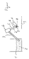
- Carbon dioxide particles 2 are separated from a collecting container 1 with solid carbon dioxide particles 2 via a screw conveyor 3 and fed to a Venturi nozzle 4. In the Venturi nozzle 4, the carbon dioxide particles 2 are taken up by a generated gas stream 5.
- the gas stream 5 with the absorbed carbon dioxide particles 2 is directed to an area in which a tool 6, for example a spindle with a drill bit, processes a workpiece 7.
- the tool can also be a lathe or milling machine or generally a machining center. Machining products particles 8, ie chips and dust particles, are produced in a known manner during machining. Since the machining products are generated in the area covered by the workpiece 5, they are largely hit by CO 2 particles 2.
- This impingement releases the kinetic energy of the CO 2 particles and, if applicable, the cutting product particles when braking.
- This released kinetic energy leads to evaporation or sublimation of the solid carbon dioxide particles into gaseous carbon dioxide.
- the evaporating particle extracts heat from the surroundings, as a result of which, in particular, the machining product particle 8 is cooled.
- these machining product particles 8 are braked by the impact with the CO 2 particles 2 or directed in the direction of flight of the CO 2 particles 2 and the gas stream 5.
- the particles 8 are subsequently carried along by the gas stream 5, which reaches a suction device 9.
- the suction device By using the suction device, the gas flow from the Venturi nozzle 4 to this suction device can be maintained, so that a distribution of the particles 8 in the processing space is thereby further restricted.
- a chip conveyor can be provided, which continuously removes the machining products generated.
- the cutting surface of the workpiece 7 on which this is from the tool 6 is processed by minimal quantity lubrication, which is advantageously carried out via the tool 6, lubricated. Because the gas flow with carbon dioxide particles into one Cooling of the tool and workpiece, especially the Cutting surface is the use of additional coolant unnecessary.
- a temperature sensor z. B. provided on the tool become excessively heated, the cooling effect can be increased by either increasing the gas flow or the amount of particles conveyed by the screw conveyor 3 is increased becomes.
- the strength of the gas stream can e.g. B. via a setting of Pressure of the compressed air used or under pressure Nitrogen.
- the CO 2 particles are, for example, elongated and have, for example, a length of a few millimeters and a diameter of 0.5-2 mm.
Landscapes
- Engineering & Computer Science (AREA)
- Mechanical Engineering (AREA)
- Physics & Mathematics (AREA)
- Fluid Mechanics (AREA)
- Auxiliary Devices For Machine Tools (AREA)
- Turning (AREA)
Abstract
Description
Claims (13)
- Verfahren zum Abführen von Zerspanungsprodukten eines zerspanenden Bearbeitungsverfahrens, bei dem feste CO2-Teilchen (2) über eine Fördereinrichtung (3) einem Gasstrom (5) zugeführt werden,der Gasstrom mit aufgenommenen festen CO2-Teilchen (2) einem Bearbeitungsraum zugeführt wird, in dem das Bearbeitungsverfahren durchgeführt wird, und auf einen Bereich in dem Bearbeitungsraum gerichtet wird, in dem ein Werkstück (7) von einem Werkzeug (6) zerspanend bearbeitet wird, undzumindest ein Großteil der erzeugten Zerspanungsprodukte (8) von dem Gasstrom derartig erfaßt wird, dass die Zerspanungsprodukte von den CO2-Teilchen getroffen werden.
- Verfahren nach Anspruch 1, dadurch gekennzeichnet, daß die CO2-Teilchen (2) über die Fördereinrichtung, vorzugsweise eine Förderschnecke (3), vereinzelt und nachfolgend einer Venturidüse (4) zugeführt werden, in der sie von dem Gasstrom (5) erfaßt werden.
- Verfahren nach Anspruch 1 oder 2, dadurch gekennzeichnet, daß ein Gasstrom (5) aus Druckluft oder unter Druck stehendem Stickstoff verwendet wird.
- Verfahren nach einem der Ansprüche 1 bis 3, dadurch gekennzeichnet, dass die Zufuhrmenge von CO2-Teilchen und/oder der Gasstrom variiert werden.
- Verfahren nach Anspruch 4, dadurch gekennzeichnet, dass die Zufuhrmenge von CO2-Teilchen und/oder der Gasstrom derartig eingestellt werden, dass ein Großteil der erzeugten Zerspanungsprodukte von den CO2-Teilchen getroffen wird.
- Verfahren nach einem der Ansprüche 1 bis 5, dadurch gekennzeichnet, daß der Gasstrom und gasförmiges CO2 aus dem Bearbeitungsraum abgesaugt werden, vorzugsweise durch eine Absaugung unterhalb des Bereichs des Werkstücks (7) und Werkzeugs (6), wobei insbesondere gleichzeitig Zerspanungsprodukte abtransportiert werden.
- Verfahren nach einem der Ansprüche 1 bis 6, dadurch gekennzeichnet, dass die CO2-Teilchen aus gepresstem CO2-Schnee bestehen.
- Zerspanendes Bearbeitungsverfahren, bei dem ein Werkstück von einem Werkzeug (6) unter Erzeugung von Zerspanungsprodukten (8), insbesondere Spänen oder Staub, bearbeitet wird und die Zerspanungsprodukte abgeführt werden, dadurch gekennzeichnet, daß ein Verfahren zum Abführen der Zerspanungsprodukte nach einem der Ansprüche 1 bis 7 angewendet wird, wobei der Gasstrom mit aufgenommenen CO2-Teilchen das Werkstück und das Werkzeug zumindest im Bereich der Schnittfläche erfaßt und weiterhin zumindest einen Großteil der erzeugten Zerspanungsprodukte von den CO2-Teilchen getroffen werden, und ein Schmiermittel über das Werkzeug der Schnittfläche zugeführt wird.
- Bearbeitungsverfahren nach Anspruch 8, dadurch gekennzeichnet, daß eine Minimalmengenschmierung vorgenommen wird und eine Kühlung von Werkzeug und Werkstück durch Variation des Gasstroms und/oder der Menge von zugeführten CO2-Teilchen eingestellt wird.
- Bearbeitungsverfahren nach Anspruch 8 oder 9, dadurch gekennzeichnet, daß ein Werkstück aus Aluminium oder Magnesium bzw. einer Aluminium- oder Magnesiumlegierung bearbeitet wird, wobei vorteilhafterweise ein Inertgas wie z.B. Stickstoff für den Gasstrom verwendet wird.
- Berarbeitungsverfahren nach einem der Ansprüche 8 bis 10, dadurch gekennzeichnet, daß es ein Dreh-, Fräs-, Hohn- oder Bohrverfahren ist.
- Bearbeitungsverfahren nach einem der Ansprüche 8 bis 11, dadurch gekennzeichnet, daß nach Fertigstellung des Werkstücks dieses durch den Gasstrom mit CO2-Teilchen gereinigt wird, wobei das Werkstück vorzugsweise gewendet wird.
- Bearbeitungsverfahren nach einem der Ansprüche 8 bis 12, dadurch gekennzeichnet, daß während der Bearbeitung des Werkstücks oder vor oder nach Fertigstellung des Werkstücks die Werkzeugmaschine und vorteilhafterweise auch der Bearbeitungsraum durch den Gasstrom mit CO2-Teilchen gesäubert wird.
Applications Claiming Priority (2)
| Application Number | Priority Date | Filing Date | Title |
|---|---|---|---|
| DE19915619A DE19915619A1 (de) | 1999-04-07 | 1999-04-07 | Verfahren zum Abführen von Zerspanungsprodukten eines zerspanenden Bearbeitungsverfahrens |
| DE19915619 | 1999-04-07 |
Publications (2)
| Publication Number | Publication Date |
|---|---|
| EP1044762A2 true EP1044762A2 (de) | 2000-10-18 |
| EP1044762A3 EP1044762A3 (de) | 2002-09-04 |
Family
ID=7903743
Family Applications (1)
| Application Number | Title | Priority Date | Filing Date |
|---|---|---|---|
| EP00105826A Withdrawn EP1044762A3 (de) | 1999-04-07 | 2000-03-20 | Verfahren zum Abführen von Zerspanungsprodukten eines zerspanenden Bearbeitungsverfahrens |
Country Status (3)
| Country | Link |
|---|---|
| US (1) | US6382886B1 (de) |
| EP (1) | EP1044762A3 (de) |
| DE (1) | DE19915619A1 (de) |
Cited By (8)
| Publication number | Priority date | Publication date | Assignee | Title |
|---|---|---|---|---|
| EP1356890A1 (de) * | 2002-04-24 | 2003-10-29 | The BOC Group plc | Verfahren zum Bearbeiten/Schweissen von Metall mit der Hilfe von Kryogendurchfluss |
| WO2008104341A1 (de) * | 2007-02-28 | 2008-09-04 | Raimund Rerucha | Verfahren zur bearbeitung von werkstücken mit stickstoffzufuhr |
| WO2012052650A1 (fr) | 2010-10-22 | 2012-04-26 | L'air Liquide,Societe Anonyme Pour L'etude Et L'exploitation Des Procedes Georges Claude | Procédé et installation d'usinage avec refroidissement cryogénique |
| CN103801979A (zh) * | 2014-02-10 | 2014-05-21 | 常州大学 | 一种干冰冷却的干式切削方法 |
| WO2014090813A1 (en) * | 2012-12-12 | 2014-06-19 | Sandvik Materials Technology Deutschland Gmbh | Processing machine and method for working the end of a pipe |
| US9808844B2 (en) | 2013-03-18 | 2017-11-07 | Sandvik Materials Technology Deutschland Gmbh | Method for producing a steel tube including cleaning of the outer tube wall |
| US9839949B2 (en) | 2013-03-18 | 2017-12-12 | Sandvik Materials Technology Deutschland Gmbh | Method for producing a steel tube including cleaning of the inner tube wall |
| WO2018046543A1 (de) * | 2016-09-08 | 2018-03-15 | Thielenhaus Technologies Gmbh | Maschine mit reinigungseinrichtung und optischer messeinrichtung |
Families Citing this family (12)
| Publication number | Priority date | Publication date | Assignee | Title |
|---|---|---|---|---|
| ATE445479T1 (de) * | 2001-04-25 | 2009-10-15 | Tornos Sa Fabrique De Machine | Optimierungsverfahren zum betrieb einer werkzeugmaschine durch einstellung der temperatur |
| DE10140718A1 (de) | 2001-08-27 | 2003-04-03 | Walter Jaeger | Verfahren und Werkzeug zur Bearbeitung von Werkstücken mit Kühlung |
| JP3949504B2 (ja) * | 2002-04-25 | 2007-07-25 | 英夫 吉田 | 母材表面の活性化処理方法および活性化処理装置 |
| DE10222040A1 (de) * | 2002-05-17 | 2003-12-04 | Kennametal Inc | Fräswerkzeug |
| US7073244B2 (en) * | 2002-09-20 | 2006-07-11 | Lear Corporation | Process for machining a flexible foam |
| DE102004001475B4 (de) * | 2004-01-08 | 2006-02-02 | Leica Mikrosysteme Gmbh | Verfahren zum Trimmen von Proben |
| DE102004024979B3 (de) * | 2004-05-21 | 2006-01-12 | Alexander Binzel Schweisstechnik Gmbh & Co. Kg | Verfahren und Vorrichtung zum Reinigen einer beim Widerstandspunktschweißen eingesetzten Elektrode oder Kappe sowie Vorrichtung zum Widerstandspunktschweißen |
| US20060123801A1 (en) * | 2004-12-13 | 2006-06-15 | Cool Clean Technologies, Inc. | Device for applying cryogenic composition and method of using same |
| DE102006011392B4 (de) * | 2006-03-09 | 2008-04-24 | Grob-Werke Gmbh & Co. Kg | Vorrichtung zum Reinigen des Spannbereiches eines Bearbeitungswerkzeuges |
| DE102008021049B3 (de) * | 2008-04-26 | 2009-12-10 | Ex-Cell-O Gmbh | Verfahren zum Kühlen und Schmieren eines Werkzeugs und zum Reinigen der bearbeiteten Fläche |
| DE102013206143A1 (de) | 2013-04-08 | 2014-10-09 | Gühring KG | Werkzeughalter |
| DE102024112834B3 (de) * | 2024-05-07 | 2025-06-18 | P&L Gmbh & Co. Kg | Werkzeugmaschine und Verfahren mit verbesserter Kühlung |
Family Cites Families (19)
| Publication number | Priority date | Publication date | Assignee | Title |
|---|---|---|---|---|
| US4389820A (en) * | 1980-12-29 | 1983-06-28 | Lockheed Corporation | Blasting machine utilizing sublimable particles |
| FR2576821B1 (fr) * | 1985-02-04 | 1987-03-27 | Carboxyque Francaise | Installation pour la projection de particules de glace carbonique |
| US4829859A (en) * | 1986-08-29 | 1989-05-16 | Ulticon Systems, Inc. | Method of high speed machining |
| US5129190A (en) * | 1990-10-31 | 1992-07-14 | Eaton Corporation | Machining and apparatus |
| US5108512A (en) * | 1991-09-16 | 1992-04-28 | Hemlock Semiconductor Corporation | Cleaning of CVD reactor used in the production of polycrystalline silicon by impacting with carbon dioxide pellets |
| DE4230625A1 (de) * | 1992-09-12 | 1994-03-17 | Wuerth Elektronik Gmbh & Co Kg | Verfahren und Vorrichtung zum Bohren von Leiterplatten |
| DE4326517C2 (de) * | 1993-08-06 | 1998-06-10 | Linde Ag | Verfahren zur spanenden Bearbeitung von metallischen Werkstücken mit Kühlung |
| US5733174A (en) * | 1994-01-07 | 1998-03-31 | Lockheed Idaho Technologies Company | Method and apparatus for cutting, abrading, and drilling with sublimable particles and vaporous liquids |
| FR2724337A1 (fr) * | 1994-09-09 | 1996-03-15 | Anhydride Carbonique Ind | Procede et equipement pour le refroidissement de la zone de travail d'un materiau a usiner |
| US5503198A (en) * | 1994-10-14 | 1996-04-02 | Becker; James R. | Method and apparatus for filling containers with dry ice pellets |
| US5632150A (en) * | 1995-06-07 | 1997-05-27 | Liquid Carbonic Corporation | Carbon dioxide pellet blast and carrier gas system |
| US5651834A (en) * | 1995-08-30 | 1997-07-29 | Lucent Technologies Inc. | Method and apparatus for CO2 cleaning with mitigated ESD |
| US5645382A (en) * | 1995-09-13 | 1997-07-08 | Cargill Detroit Corporation | Controlled atmosphere machining |
| US5592863A (en) * | 1995-09-25 | 1997-01-14 | Xerox Corporation | Cryogenic machining of soft/ductile materials |
| EP0786311B1 (de) * | 1995-10-30 | 2000-06-14 | Birgit Papcke | Verfahren zur Oberflächenbehandlung, insbesondere Reinigung von Oberflächen mit CO2-Trockeneisgranulat und eine Vorrichtung zur Durchführung dieses Verfahrens |
| DE19725345C2 (de) * | 1997-06-16 | 2002-11-07 | Bielomatik Leuze & Co | Schmiervorrichtung |
| DE19734628A1 (de) * | 1997-08-09 | 1999-02-11 | Bernhard Ringler | Verfahren zum Beseitigen von an der Bearbeitungsstelle im Arbeitsraum einer Bearbeitungsmaschine anfallenden Bearbeitungsrückständen sowie Vorrichtung zur Durchführung dieses Verfahrens |
| US6200198B1 (en) * | 1997-10-20 | 2001-03-13 | Enshu Limited | Method of cutting of metal materials and non-metal materials in a non-combustible gas atmosphere |
| US6174225B1 (en) * | 1997-11-13 | 2001-01-16 | Waste Minimization And Containment Inc. | Dry ice pellet surface removal apparatus and method |
-
1999
- 1999-04-07 DE DE19915619A patent/DE19915619A1/de not_active Withdrawn
-
2000
- 2000-03-20 EP EP00105826A patent/EP1044762A3/de not_active Withdrawn
- 2000-04-07 US US09/545,511 patent/US6382886B1/en not_active Expired - Fee Related
Cited By (14)
| Publication number | Priority date | Publication date | Assignee | Title |
|---|---|---|---|---|
| EP1356890A1 (de) * | 2002-04-24 | 2003-10-29 | The BOC Group plc | Verfahren zum Bearbeiten/Schweissen von Metall mit der Hilfe von Kryogendurchfluss |
| US7067759B2 (en) | 2002-04-24 | 2006-06-27 | The Boc Group Plc | Metal working |
| WO2008104341A1 (de) * | 2007-02-28 | 2008-09-04 | Raimund Rerucha | Verfahren zur bearbeitung von werkstücken mit stickstoffzufuhr |
| WO2012052650A1 (fr) | 2010-10-22 | 2012-04-26 | L'air Liquide,Societe Anonyme Pour L'etude Et L'exploitation Des Procedes Georges Claude | Procédé et installation d'usinage avec refroidissement cryogénique |
| FR2966371A1 (fr) * | 2010-10-22 | 2012-04-27 | Air Liquide | Procede et installation d'usinage avec refroidissement cryogenique |
| WO2014090813A1 (en) * | 2012-12-12 | 2014-06-19 | Sandvik Materials Technology Deutschland Gmbh | Processing machine and method for working the end of a pipe |
| CN104903047A (zh) * | 2012-12-12 | 2015-09-09 | 山特维克原料技术德国公开股份有限公司 | 用于加工管子的端部的加工机器和方法 |
| US10092958B2 (en) | 2012-12-12 | 2018-10-09 | Sandvik Materials Technology Deutschland Gmbh | Processing machine and method for working the end of a pipe |
| CN104903047B (zh) * | 2012-12-12 | 2019-02-15 | 山特维克原料技术德国公开股份有限公司 | 用于加工管子的端部的加工机器和方法 |
| US9808844B2 (en) | 2013-03-18 | 2017-11-07 | Sandvik Materials Technology Deutschland Gmbh | Method for producing a steel tube including cleaning of the outer tube wall |
| US9839949B2 (en) | 2013-03-18 | 2017-12-12 | Sandvik Materials Technology Deutschland Gmbh | Method for producing a steel tube including cleaning of the inner tube wall |
| CN103801979A (zh) * | 2014-02-10 | 2014-05-21 | 常州大学 | 一种干冰冷却的干式切削方法 |
| WO2018046543A1 (de) * | 2016-09-08 | 2018-03-15 | Thielenhaus Technologies Gmbh | Maschine mit reinigungseinrichtung und optischer messeinrichtung |
| US20190184512A1 (en) * | 2016-09-08 | 2019-06-20 | Thielenhaus Technologies Gmbh | A machine having a cleaning device and optical measuring device |
Also Published As
| Publication number | Publication date |
|---|---|
| DE19915619A1 (de) | 2000-10-19 |
| EP1044762A3 (de) | 2002-09-04 |
| US6382886B1 (en) | 2002-05-07 |
Similar Documents
| Publication | Publication Date | Title |
|---|---|---|
| EP1044762A2 (de) | Verfahren zum Abführen von Zerspanungsprodukten eines zerspanenden Bearbeitungsverfahrens | |
| DE4326253C2 (de) | Kühl- und Staubabsaugvorrichtung für eine Werkzeugmaschine | |
| DE69527293T2 (de) | Kryogenarbeiten | |
| DE69218846T2 (de) | Verfahren und Vorrichtung zur Herstellung von Pulver, insbesondere Metallpulver durch Atomisierung | |
| DE112017000093B4 (de) | Flüssigkeitsversorgungsdüsenstruktur zur Minimalmengenschmierung beim Hochgeschwindigkeitsfräsen und System | |
| EP1420918A1 (de) | Verfahren und werkzeug zur bearbeitung von werkstücken mit kühlung | |
| EP3725439B1 (de) | Herstellung eines metall-pulvers einer aluminiumlegierung zur verwendung als werkstoff in der additiven fertigung | |
| DE7729871U1 (de) | Vorrichtung zum Schneiden eines metallischen Werkstücks | |
| DE10256460A1 (de) | Herstellungsverfahren für ein Produkt mit einem aufgesprühten Beschichtungsfilm | |
| DE2254491A1 (de) | Verfahren zum beschichten von oberflaechen an werkstuecken durch aufspritzen von schichtstoffen, vorzugsweise durch plasmaspritzen sowie anordnung zur durchfuehrung des verfahrens | |
| WO2018033618A1 (de) | Verfahren zum betrieb einer spanenden werkzeugmaschine und werkzeugmaschine für die spanende bearbeitung von werkstücken | |
| EP0458180A2 (de) | Verfahren und Vorrichtung zum Laserstrahlschneiden | |
| EP0156760A2 (de) | Verfahren und Vorrichtung zur Herstellung eines warmarbeitswerkzeuges | |
| DE4326517C2 (de) | Verfahren zur spanenden Bearbeitung von metallischen Werkstücken mit Kühlung | |
| DE4439114A1 (de) | Verfahren und Vorrichtung zur trockenen, spanabhebenden Bearbeitung eines Werkstücks | |
| DE2622603A1 (de) | Verfahren zur herstellung von metallpulver | |
| DE19525989A1 (de) | Lochformverfahren und Lochvorrichtung | |
| WO2008104341A1 (de) | Verfahren zur bearbeitung von werkstücken mit stickstoffzufuhr | |
| DE69826772T2 (de) | Zahnradwälzstoss-Verfahren und -Maschine | |
| EP0471048A1 (de) | Halbzeug aus kupfer oder einer kupferlegierung mit kohlenstoffzusatz | |
| EP0007536B1 (de) | Verfahren und Vorrichtung zur Granulierung einer Metallschmelze zwecks Pulverherstellung | |
| EP3544768B1 (de) | Verfahren zur oberflächenbearbeitung und verwendung eines additivs | |
| DE4326518A1 (de) | Verfahren zur spanenden Bearbeitung von kunststofflichen Werkstücken | |
| DE3939374A1 (de) | Verfahren zur spanenden bearbeitung von thermoplastischen kunststoffen | |
| EP0256449B1 (de) | Pulvermetallurgische Herstellung eines Werkstücks aus einer warmfesten Aluminiumlegierung |
Legal Events
| Date | Code | Title | Description |
|---|---|---|---|
| PUAI | Public reference made under article 153(3) epc to a published international application that has entered the european phase |
Free format text: ORIGINAL CODE: 0009012 |
|
| AK | Designated contracting states |
Kind code of ref document: A2 Designated state(s): AT BE CH CY DE DK ES FI FR GB GR IE IT LI LU MC NL PT SE |
|
| AX | Request for extension of the european patent |
Free format text: AL;LT;LV;MK;RO;SI |
|
| PUAL | Search report despatched |
Free format text: ORIGINAL CODE: 0009013 |
|
| AK | Designated contracting states |
Kind code of ref document: A3 Designated state(s): AT BE CH CY DE DK ES FI FR GB GR IE IT LI LU MC NL PT SE |
|
| AX | Request for extension of the european patent |
Free format text: AL;LT;LV;MK;RO;SI |
|
| RIC1 | Information provided on ipc code assigned before grant |
Free format text: 7B 23Q 11/00 A, 7B 23Q 11/10 B |
|
| 17P | Request for examination filed |
Effective date: 20030116 |
|
| AKX | Designation fees paid |
Designated state(s): AT BE CH CY DE DK ES FI FR GB GR IE IT LI LU MC NL PT SE |
|
| 17Q | First examination report despatched |
Effective date: 20040413 |
|
| 19U | Interruption of proceedings before grant |
Effective date: 20040831 |
|
| 19W | Proceedings resumed before grant after interruption of proceedings |
Effective date: 20050301 |
|
| STAA | Information on the status of an ep patent application or granted ep patent |
Free format text: STATUS: THE APPLICATION IS DEEMED TO BE WITHDRAWN |
|
| 18D | Application deemed to be withdrawn |
Effective date: 20040820 |