EP1044761B1 - Fräsvorrichtung, insbesondere für Anwendungen im Dental-Bereich - Google Patents
Fräsvorrichtung, insbesondere für Anwendungen im Dental-Bereich Download PDFInfo
- Publication number
- EP1044761B1 EP1044761B1 EP00107853A EP00107853A EP1044761B1 EP 1044761 B1 EP1044761 B1 EP 1044761B1 EP 00107853 A EP00107853 A EP 00107853A EP 00107853 A EP00107853 A EP 00107853A EP 1044761 B1 EP1044761 B1 EP 1044761B1
- Authority
- EP
- European Patent Office
- Prior art keywords
- milling
- arm
- milling apparatus
- tool
- pillar
- Prior art date
- Legal status (The legal status is an assumption and is not a legal conclusion. Google has not performed a legal analysis and makes no representation as to the accuracy of the status listed.)
- Expired - Lifetime
Links
- 238000003801 milling Methods 0.000 title claims abstract description 63
- 230000006870 function Effects 0.000 claims description 5
- 238000000034 method Methods 0.000 description 4
- 239000000523 sample Substances 0.000 description 3
- 230000006978 adaptation Effects 0.000 description 2
- 230000008901 benefit Effects 0.000 description 2
- 230000015572 biosynthetic process Effects 0.000 description 2
- 238000005286 illumination Methods 0.000 description 2
- 238000003754 machining Methods 0.000 description 2
- 238000010792 warming Methods 0.000 description 2
- 244000261422 Lysimachia clethroides Species 0.000 description 1
- 230000009286 beneficial effect Effects 0.000 description 1
- 230000008859 change Effects 0.000 description 1
- 230000002996 emotional effect Effects 0.000 description 1
- 238000004519 manufacturing process Methods 0.000 description 1
- 239000011505 plaster Substances 0.000 description 1
- 230000008569 process Effects 0.000 description 1
Images


Classifications
-
- B—PERFORMING OPERATIONS; TRANSPORTING
- B25—HAND TOOLS; PORTABLE POWER-DRIVEN TOOLS; MANIPULATORS
- B25H—WORKSHOP EQUIPMENT, e.g. FOR MARKING-OUT WORK; STORAGE MEANS FOR WORKSHOPS
- B25H1/00—Work benches; Portable stands or supports for positioning portable tools or work to be operated on thereby
- B25H1/0021—Stands, supports or guiding devices for positioning portable tools or for securing them to the work
-
- A—HUMAN NECESSITIES
- A61—MEDICAL OR VETERINARY SCIENCE; HYGIENE
- A61C—DENTISTRY; APPARATUS OR METHODS FOR ORAL OR DENTAL HYGIENE
- A61C13/00—Dental prostheses; Making same
- A61C13/12—Tools for fastening artificial teeth; Holders, clamps, or stands for artificial teeth
-
- B—PERFORMING OPERATIONS; TRANSPORTING
- B23—MACHINE TOOLS; METAL-WORKING NOT OTHERWISE PROVIDED FOR
- B23Q—DETAILS, COMPONENTS, OR ACCESSORIES FOR MACHINE TOOLS, e.g. ARRANGEMENTS FOR COPYING OR CONTROLLING; MACHINE TOOLS IN GENERAL CHARACTERISED BY THE CONSTRUCTION OF PARTICULAR DETAILS OR COMPONENTS; COMBINATIONS OR ASSOCIATIONS OF METAL-WORKING MACHINES, NOT DIRECTED TO A PARTICULAR RESULT
- B23Q17/00—Arrangements for observing, indicating or measuring on machine tools
- B23Q17/24—Arrangements for observing, indicating or measuring on machine tools using optics or electromagnetic waves
- B23Q17/2404—Arrangements for improving direct observation of the working space, e.g. using mirrors or lamps
-
- B—PERFORMING OPERATIONS; TRANSPORTING
- B25—HAND TOOLS; PORTABLE POWER-DRIVEN TOOLS; MANIPULATORS
- B25H—WORKSHOP EQUIPMENT, e.g. FOR MARKING-OUT WORK; STORAGE MEANS FOR WORKSHOPS
- B25H1/00—Work benches; Portable stands or supports for positioning portable tools or work to be operated on thereby
- B25H1/02—Work benches; Portable stands or supports for positioning portable tools or work to be operated on thereby of table type
Definitions
- the invention relates to a milling device, in particular for applications in the dental field, consisting of a Device foot with a tool column, further from one Milling head, which has an extension arm on the tool column is connected, as well as a support for the Workpiece serving cutter, the milling head in fixed height connected to the tool column and the Height adjustable milling cutter on the tool column is arranged.
- Such milling devices are in many Known in practice and serve to Dental models using milling cutters, drills or to work with such rotating tools.
- US-A-4 411 626 describes a method as well a device for producing a crown part, wherein a numerically controlled processing machine with a Clamping device for the model to be machined Group of teeth or a tooth stump is used.
- a probe and a guide device for Provided along the probe on the tooth stump being carried along the probe on the tooth stump
- Position data recorded and stored in a memory become.
- a contour tool is then used on the basis of this data under the control of a computer relative to the tooth stump emotional.
- the DE-A-33 28 917 a to be attached to a work table Armrest, one armrest next to each side a work block to be attached to the table is provided.
- the one for attachment during the Editing a model serving work block on the one hand and the armrests that make working on the model easier on the other hand, there is no fixed relationship with it to each other, so they depend on the chosen one Place of attachment to the table. Otherwise, this arrangement obviously only for manual work on the Model provided. Therefore, probably only used hand-held tools, including those that are fixed Milling devices are not to be expected.
- DE-A-36 04 531 also describes a Method and an apparatus for the production of Tooth replacement parts, in which a 3-axis milling machine for Machining one arranged on a coordinate table Plaster model is used.
- a 3-axis milling machine for Machining one arranged on a coordinate table Plaster model is used.
- a fully automatic milling process is programmable.
- the invention has for its object a To design the milling device of the type mentioned at the beginning that the operation and handling, even with the respective Change of model, simplified and adjustments and settings made quickly and easily and can be maintained.
- a support column is provided on the device base, which runs axially parallel to the tool column and at least carries a cantilever arm with an arm / hand rest.
- the advantage achieved by the invention is essential in that because of its height fixed milling head, with which also the milling tool and so that the processing location remains at the same level, as well the arm / handrests that can be determined in contrast unchanged working posture is guaranteed. A Adaptation to different height models or substructures these settings do not affect the model.
- each arm / hand rest is one Articulation with a vertical articulation axis on the extension arm stored, which increases the distance between the arm / hand rest from the milling table light - according to the needs - can be adjusted.
- each arm / hand rest on a horizontal drive shaft is arranged, one end of which is connected to the joint. This is also the Tilt the arm / hand rest towards the milling cutter individually adaptable. For this it is then necessary that the arm / hand rest using a locking screw can be locked in a rotationally fixed manner on the drive shaft.
- the support column advantageously extends through a hole in the milling plate.
- Another advantageous embodiment of the invention is characterized in that an operating element for Control the main functions during the Milling process is provided, the control element in its position is freely adjustable. This has the Advantage that during the milling process Operating functions can be carried out without the selected direction of view must be changed, what with handheld milling is extremely important. In particular optimal milling results are achieved.
- Control element is arranged on a flexible arm that is connected to the device base. Then it can Control element in every required position, i.e. left, right, top, bottom, front or back and is also left-handed or right-handed operable. This gives the dental technician full freedom of movement Operating freedom when using this Milling device.
- a on the milling head Light attachment is arranged on the milling spindle concentrically encloses and on the milling cutter facing end face with several lighting elements is provided. This ensures optimal illumination of the Working area reached without shadow formation. Moreover the light attachment does not disturb or hinder the work.
- the lighting elements are expediently uniformly above arranged around the circumference and formed by LEDs, whereby no warming occurs.
- the Power supply of the light attachment by means of a integrated plug connection via the milling head.
- the milling device shown in the drawing is especially intended for applications in the dental field and consists of a device foot 1 with a Tool column 2, further from a milling head 3, the a cantilever arm 4 connected to the tool column 2 is, as well as from a as a support for the workpiece serving milling cutter 5.
- the milling head 3 is easy to use connected to tool column 2 at a fixed height. This means that the machining height always remains the same. Therefore the milling cutter 5 is height adjustable on the Tool column 2 arranged.
- a support column 6 is provided, which axially parallel to the tool column 2 and two Extension arms 7, each with an arm / hand rest 8 wearing.
- Each arm / hand rest 8 is about one Joint 9 with a vertical joint axis on the extension arm 7 stored.
- the joint 9 is not shown in FIG Provide way with several locking positions.
- the Arm / hand rest 8 by means of a locking screw 11 lockable on the PTO shaft 10. Also are the two extension arms 7 are adjustable in height and / or rotatably arranged on the support column 6 and by a additional locking screw 12 lockable.
- the support column 6 itself extends through a Bore 13 in the cutter 5, so that its height adjustment is possible undisturbed.
- the control element 14 is in his Position freely adjustable.
- the control element 14 is on a flexible arm 15, in particular a gooseneck arranged on Device foot 1 is connected. This can do that Control element 14 in any required position, that is left, right, up, down, front or back be and is equally from left or right Right-handed operable.
- the dental technician thus has full Freedom of movement and operation when using this Milling device.
- the lighting elements 17 are uniform over the circumference distributed and formed by LEDs, which means none Warming occurs.
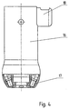
- the light attachment 16 is powered by an integrated plug connection 18 via the milling head 3, as indicated in Fig. 4, thereby disturbing Cable connections can be avoided.
Landscapes
- Health & Medical Sciences (AREA)
- Mechanical Engineering (AREA)
- Engineering & Computer Science (AREA)
- Epidemiology (AREA)
- Life Sciences & Earth Sciences (AREA)
- Animal Behavior & Ethology (AREA)
- General Health & Medical Sciences (AREA)
- Public Health (AREA)
- Veterinary Medicine (AREA)
- Dentistry (AREA)
- Oral & Maxillofacial Surgery (AREA)
- Physics & Mathematics (AREA)
- Optics & Photonics (AREA)
- Dental Tools And Instruments Or Auxiliary Dental Instruments (AREA)
Description
- Fig. 1
- die Fräsvorrichtung in perspektivischer Darstellung,
- Fig. 2
- den Gegenstand nach Fig. 1 in geänderter Ansicht,
- Fig. 3
- eine weitere Ansicht des Gegenstands nach Fig. 1,
- Fig. 4
- eine Detailansicht des Lichtaufsatzes.
Claims (12)
- Fräsvorrichtung, insbesondere für Anwendungen im Dental-Bereich, bestehend aus einem Vorrichtungsfuß (1) mit einer Werkzeugsäule (2), ferner aus einem Fräskopf (3), der über einen Auslegerarm (4) an der Werkzeugsäule (2) angeschlossen ist, sowie einem als Auflage für das Werkstück dienenden Frästeller (5), wobei der Fräskopf (3) in fester Höhe an der Werkzeugsäule (2) angeschlossen und der Frästeller (5) höhenverstellbar an der Werkzeugsäule (2) angeordnet ist, dadurch gekennzeichnet, daß am Vorrichtungsfuß (1) eine Haltesäule (6) vorgesehen ist, die achsparallel zur Werkzeugsäule (2) verläuft und wenigstens einen Auslegerarm (7) mit einer Arm-/ Handauflage (8) trägt.
- Fräsvorrichtung nach Anspruch 1, dadurch gekennzeichnet, daß jede Arm-/ Handauflage (8) über ein Gelenk (9) mit senkrechter Gelenkachse an dem Auslegerarm (7) gelagert ist.
- Fräsvorrichtung nach Anspruch 2, dadurch gekennzeichnet, daß das Gelenk (9) mit mehreren Raststellungen versehen ist.
- Fräsvorrichtung nach Anspruch 2 oder 3, dadurch gekennzeichnet, daß jede Arm-/Handauflage (8) auf einer horizontalen Gelenkwelle (10) angeordnet ist, deren eines Ende an dem Gelenk (9) angeschlossen ist.
- Fräsvorrichtung nach Anspruch 4, dadurch gekennzeichnet, daß die Arm-/ Handauflage (8) mittels einer Feststellschraube (11) drehfest auf der Gelenkwelle (10) arretierbar ist.
- Fräsvorrichtung nach einem der Ansprüche 1 bis 5, dadurch gekennzeichnet, daß der Auslegerarm (7) bzw. die Auslegerarme höhenverstellbar und/oder drehbar auf der Haltesäule (6) angeordnet und durch eine Arretierschraube (12) feststellbar ist.
- Fräsvorrichtung nach einem der Ansprüche 1 bis 3, dadurch gekennzeichnet, daß die Haltesäule (6) sich durch eine Bohrung (13) im Frästeller (5) erstreckt.
- Fräsvorrichtung nach einem der Ansprüche 1 bis 7, dadurch gekennzeichnet, daß ein Bedienelement (14) zur Steuerung der wichtigsten Funktionen während des Fräsvorganges vorgesehen ist, wobei das Bedienelement (14) in seiner Position frei verstellbar ist.
- Fräsvorrichtung nach Anspruch 8, dadurch gekennzeichnet, daß das Bedienelement (14) an einem flexiblen Arm (15) angeordnet ist, der am Vorrichtungsfuß (1) angeschlossen ist.
- Fräsvorrichtung nach einem der Ansprüche 1 bis 9, dadurch gekennzeichnet, daß am Fräskopf (3) ein Lichtaufsatz (16) angeordnet ist, der die Frässpindel konzentrisch umschließt und an seiner dem Fräser zugewandten Stirnseite mit mehreren Leuchtelementen (17) versehen ist.
- Fräsvorrichtung nach Anspruch 10, dadurch gekennzeichnet, daß die Leuchtelemente (17) gleichmäßig über den Umfang verteilt angeordnet und von LED's gebildet sind.
- Fräsvorrichtung nach Anspruch 10 oder 11, dadurch gekennzeichnet, daß die Stromversorgung des Lichtaufsatzes (16) mittels einer integrierten Steckverbindung (18) über den Fräskopf erfolgt.
Applications Claiming Priority (2)
| Application Number | Priority Date | Filing Date | Title |
|---|---|---|---|
| DE19916449 | 1999-04-12 | ||
| DE19916449A DE19916449A1 (de) | 1999-04-12 | 1999-04-12 | Fräsvorrichtung, insbesondere für Anwendungen im Dental-Bereich |
Publications (3)
| Publication Number | Publication Date |
|---|---|
| EP1044761A2 EP1044761A2 (de) | 2000-10-18 |
| EP1044761A3 EP1044761A3 (de) | 2002-05-02 |
| EP1044761B1 true EP1044761B1 (de) | 2003-08-20 |
Family
ID=7904269
Family Applications (1)
| Application Number | Title | Priority Date | Filing Date |
|---|---|---|---|
| EP00107853A Expired - Lifetime EP1044761B1 (de) | 1999-04-12 | 2000-04-12 | Fräsvorrichtung, insbesondere für Anwendungen im Dental-Bereich |
Country Status (3)
| Country | Link |
|---|---|
| EP (1) | EP1044761B1 (de) |
| AT (1) | ATE247540T1 (de) |
| DE (2) | DE19916449A1 (de) |
Families Citing this family (3)
| Publication number | Priority date | Publication date | Assignee | Title |
|---|---|---|---|---|
| DE102007037453A1 (de) * | 2007-08-08 | 2009-02-12 | Renfert Gmbh | Dentalgerät |
| DE102007057949A1 (de) * | 2007-12-01 | 2009-06-04 | Plappert Industrieanlagen Gmbh | Abstützvorrichtung, insbesondere an einer Bearbeitungsmaschine |
| DE102013005871A1 (de) | 2013-04-08 | 2014-10-09 | Dental Conceptworks UG | Bearbeitungszentrum |
Family Cites Families (3)
| Publication number | Priority date | Publication date | Assignee | Title |
|---|---|---|---|---|
| DE3003435A1 (de) * | 1980-01-31 | 1981-08-06 | Becker Dental-Labor Gmbh, 5100 Aachen | Verfahren und vorrichtung zur herstellung eines kronenteiles |
| DE3328917A1 (de) * | 1983-08-10 | 1985-02-28 | Kaltenbach & Voigt Gmbh & Co, 7950 Biberach | Armauflage fuer einen arbeitstisch |
| DE3604531A1 (de) * | 1986-02-13 | 1987-08-20 | Kurt Kern Gmbh & Co Kg | Verfahren zur herstellung von zahnersatzteilen und vorrichtung zur durchfuehrung dieses verfahrens |
-
1999
- 1999-04-12 DE DE19916449A patent/DE19916449A1/de not_active Withdrawn
-
2000
- 2000-04-12 EP EP00107853A patent/EP1044761B1/de not_active Expired - Lifetime
- 2000-04-12 AT AT00107853T patent/ATE247540T1/de active
- 2000-04-12 DE DE50003330T patent/DE50003330D1/de not_active Expired - Lifetime
Also Published As
| Publication number | Publication date |
|---|---|
| DE19916449A1 (de) | 2000-10-26 |
| EP1044761A3 (de) | 2002-05-02 |
| DE50003330D1 (de) | 2003-09-25 |
| EP1044761A2 (de) | 2000-10-18 |
| ATE247540T1 (de) | 2003-09-15 |
Similar Documents
| Publication | Publication Date | Title |
|---|---|---|
| EP1841382B1 (de) | Kopierfräseinrichtung zur herstellung von insbesondere zahntechnischen werkstücken | |
| DE3133488A1 (de) | "programmgesteuerte werkzeugschleifmaschine" | |
| EP2247405A2 (de) | Aufspannvorrichtung für eine rechnergesteuerte, spanabhebende bearbeitungsmaschine | |
| DE3729162A1 (de) | Werkzeugmaschine zur bearbeitung von werkstuecken mittels rundlaufender werkzeuge | |
| EP2303177A1 (de) | Bearbeitungsvorrichtung zum anfertigen einer bohrschablone für zahnimplantate | |
| DE10335272A1 (de) | Anordnung zur Führung eines Dentalimplantatbohrers, Bohrschablone sowie Bohrschablonenaufnahmeimplantat für die Anordnung und Verfahren zur Herstellung dieser Bohrschablone | |
| EP0589086A1 (de) | Zahnärztlicher Patientenstuhl | |
| DE9105600U1 (de) | Aufnahmevorrichtung für Werkstücke | |
| DE19736192C2 (de) | Bestrahlungsanlage mit mehreren auf ein Zentrum ausgerichteten Strahlenquellen | |
| EP0504691A2 (de) | Mess- und Bearbeitungsstation für grosse Werkstücke | |
| DE102008063695A1 (de) | Bohrmaschine zur Fertigung von Schablonen für die Dentalmedizin | |
| DE19709215A1 (de) | Vorrichtung und System zur Herstellung einer Bohrschablone für Implantatzähne | |
| EP1044761A2 (de) | Fräsvorrichtung, insbesondere für Anwendungen im Dental-Bereich | |
| DE3522999A1 (de) | Vorrichtung zur hornhauttransplantation am menschlichen auge | |
| DE2905579A1 (de) | Einrichtung zum gerichteten leiten von fertigungshilfsstoff | |
| DE3817833C2 (de) | ||
| DE69202732T2 (de) | Vorrichtung zum Heben einer Pflanze. | |
| DE3940797C2 (de) | ||
| DE10020811B4 (de) | Vorrichtung zum Positionieren von wenigstens einem Schablonenteil an einer Schablone für den menschlichen oder tierischen Körper, insbesondere an einer Implantatschablone | |
| EP0742075A1 (de) | Aufsatzgerät für eine Werkzeugschleifmaschine | |
| WO2008145690A2 (de) | Stützelement und behandlungsstuhl | |
| DE102005016396A1 (de) | Arbeitstisch für Zahntechniker | |
| DE4204327C2 (de) | Verfahren und Vorrichtung zum Herstellen eines medizinischen oder zahntechnischen Restaurationskörpers | |
| EP1520551A2 (de) | Arbeitstisch für Zahntechniker und Zahnärzte | |
| DE19709346A1 (de) | Vorrichtung zum Aufnehmen wenigstens eines zahnärztlichen Behandlungshilfsmittels |
Legal Events
| Date | Code | Title | Description |
|---|---|---|---|
| PUAI | Public reference made under article 153(3) epc to a published international application that has entered the european phase |
Free format text: ORIGINAL CODE: 0009012 |
|
| AK | Designated contracting states |
Kind code of ref document: A2 Designated state(s): AT BE CH CY DE DK ES FI FR GB GR IE IT LI LU MC NL PT SE |
|
| AX | Request for extension of the european patent |
Free format text: AL;LT;LV;MK;RO;SI |
|
| PUAL | Search report despatched |
Free format text: ORIGINAL CODE: 0009013 |
|
| AK | Designated contracting states |
Kind code of ref document: A3 Designated state(s): AT BE CH CY DE DK ES FI FR GB GR IE IT LI LU MC NL PT SE |
|
| AX | Request for extension of the european patent |
Free format text: AL;LT;LV;MK;RO;SI |
|
| RIC1 | Information provided on ipc code assigned before grant |
Free format text: 7B 23Q 9/00 A, 7B 25H 1/00 B, 7B 23C 1/06 B, 7A 61C 3/02 B, 7B 65H 1/00 B, 7A 61C 13/00 B |
|
| 17P | Request for examination filed |
Effective date: 20020404 |
|
| 17Q | First examination report despatched |
Effective date: 20020702 |
|
| AKX | Designation fees paid |
Free format text: AT BE CH CY DE DK ES FI FR GB GR IE IT LI LU MC NL PT SE |
|
| GRAH | Despatch of communication of intention to grant a patent |
Free format text: ORIGINAL CODE: EPIDOS IGRA |
|
| GRAS | Grant fee paid |
Free format text: ORIGINAL CODE: EPIDOSNIGR3 |
|
| GRAA | (expected) grant |
Free format text: ORIGINAL CODE: 0009210 |
|
| AK | Designated contracting states |
Designated state(s): AT BE CH CY DE DK ES FI FR GB GR IE IT LI LU MC NL PT SE |
|
| PG25 | Lapsed in a contracting state [announced via postgrant information from national office to epo] |
Ref country code: GB Free format text: LAPSE BECAUSE OF FAILURE TO SUBMIT A TRANSLATION OF THE DESCRIPTION OR TO PAY THE FEE WITHIN THE PRESCRIBED TIME-LIMIT Effective date: 20030820 Ref country code: FI Free format text: LAPSE BECAUSE OF FAILURE TO SUBMIT A TRANSLATION OF THE DESCRIPTION OR TO PAY THE FEE WITHIN THE PRESCRIBED TIME-LIMIT Effective date: 20030820 Ref country code: CY Free format text: LAPSE BECAUSE OF FAILURE TO SUBMIT A TRANSLATION OF THE DESCRIPTION OR TO PAY THE FEE WITHIN THE PRESCRIBED TIME-LIMIT Effective date: 20030820 Ref country code: NL Free format text: LAPSE BECAUSE OF FAILURE TO SUBMIT A TRANSLATION OF THE DESCRIPTION OR TO PAY THE FEE WITHIN THE PRESCRIBED TIME-LIMIT Effective date: 20030820 Ref country code: IE Free format text: LAPSE BECAUSE OF FAILURE TO SUBMIT A TRANSLATION OF THE DESCRIPTION OR TO PAY THE FEE WITHIN THE PRESCRIBED TIME-LIMIT Effective date: 20030820 |
|
| REG | Reference to a national code |
Ref country code: GB Ref legal event code: FG4D Free format text: NOT ENGLISH |
|
| REG | Reference to a national code |
Ref country code: CH Ref legal event code: EP |
|
| REG | Reference to a national code |
Ref country code: CH Ref legal event code: NV Representative=s name: ISLER & PEDRAZZINI AG |
|
| REG | Reference to a national code |
Ref country code: IE Ref legal event code: FG4D Free format text: GERMAN |
|
| REF | Corresponds to: |
Ref document number: 50003330 Country of ref document: DE Date of ref document: 20030925 Kind code of ref document: P |
|
| PG25 | Lapsed in a contracting state [announced via postgrant information from national office to epo] |
Ref country code: GR Free format text: LAPSE BECAUSE OF FAILURE TO SUBMIT A TRANSLATION OF THE DESCRIPTION OR TO PAY THE FEE WITHIN THE PRESCRIBED TIME-LIMIT Effective date: 20031120 Ref country code: SE Free format text: LAPSE BECAUSE OF FAILURE TO SUBMIT A TRANSLATION OF THE DESCRIPTION OR TO PAY THE FEE WITHIN THE PRESCRIBED TIME-LIMIT Effective date: 20031120 Ref country code: DK Free format text: LAPSE BECAUSE OF FAILURE TO SUBMIT A TRANSLATION OF THE DESCRIPTION OR TO PAY THE FEE WITHIN THE PRESCRIBED TIME-LIMIT Effective date: 20031120 |
|
| PG25 | Lapsed in a contracting state [announced via postgrant information from national office to epo] |
Ref country code: ES Free format text: LAPSE BECAUSE OF FAILURE TO SUBMIT A TRANSLATION OF THE DESCRIPTION OR TO PAY THE FEE WITHIN THE PRESCRIBED TIME-LIMIT Effective date: 20031201 |
|
| PG25 | Lapsed in a contracting state [announced via postgrant information from national office to epo] |
Ref country code: PT Free format text: LAPSE BECAUSE OF FAILURE TO SUBMIT A TRANSLATION OF THE DESCRIPTION OR TO PAY THE FEE WITHIN THE PRESCRIBED TIME-LIMIT Effective date: 20040120 |
|
| NLV1 | Nl: lapsed or annulled due to failure to fulfill the requirements of art. 29p and 29m of the patents act | ||
| GBV | Gb: ep patent (uk) treated as always having been void in accordance with gb section 77(7)/1977 [no translation filed] |
Effective date: 20030820 |
|
| REG | Reference to a national code |
Ref country code: IE Ref legal event code: FD4D |
|
| PG25 | Lapsed in a contracting state [announced via postgrant information from national office to epo] |
Ref country code: LU Free format text: LAPSE BECAUSE OF NON-PAYMENT OF DUE FEES Effective date: 20040412 |
|
| PG25 | Lapsed in a contracting state [announced via postgrant information from national office to epo] |
Ref country code: BE Free format text: LAPSE BECAUSE OF NON-PAYMENT OF DUE FEES Effective date: 20040430 Ref country code: MC Free format text: LAPSE BECAUSE OF NON-PAYMENT OF DUE FEES Effective date: 20040430 |
|
| ET | Fr: translation filed | ||
| PLBE | No opposition filed within time limit |
Free format text: ORIGINAL CODE: 0009261 |
|
| STAA | Information on the status of an ep patent application or granted ep patent |
Free format text: STATUS: NO OPPOSITION FILED WITHIN TIME LIMIT |
|
| 26N | No opposition filed |
Effective date: 20040524 |
|
| BERE | Be: lapsed |
Owner name: GEORG *SCHICK DENTAL G.M.B.H. Effective date: 20040430 |
|
| REG | Reference to a national code |
Ref country code: CH Ref legal event code: PCAR Free format text: ISLER & PEDRAZZINI AG;POSTFACH 1772;8027 ZUERICH (CH) |
|
| PGFP | Annual fee paid to national office [announced via postgrant information from national office to epo] |
Ref country code: FR Payment date: 20120210 Year of fee payment: 13 |
|
| PGFP | Annual fee paid to national office [announced via postgrant information from national office to epo] |
Ref country code: CH Payment date: 20120419 Year of fee payment: 13 |
|
| PGFP | Annual fee paid to national office [announced via postgrant information from national office to epo] |
Ref country code: IT Payment date: 20120426 Year of fee payment: 13 |
|
| PGFP | Annual fee paid to national office [announced via postgrant information from national office to epo] |
Ref country code: AT Payment date: 20120502 Year of fee payment: 13 |
|
| REG | Reference to a national code |
Ref country code: CH Ref legal event code: PL |
|
| REG | Reference to a national code |
Ref country code: AT Ref legal event code: MM01 Ref document number: 247540 Country of ref document: AT Kind code of ref document: T Effective date: 20130430 |
|
| PG25 | Lapsed in a contracting state [announced via postgrant information from national office to epo] |
Ref country code: CH Free format text: LAPSE BECAUSE OF NON-PAYMENT OF DUE FEES Effective date: 20130430 Ref country code: AT Free format text: LAPSE BECAUSE OF NON-PAYMENT OF DUE FEES Effective date: 20130430 Ref country code: LI Free format text: LAPSE BECAUSE OF NON-PAYMENT OF DUE FEES Effective date: 20130430 |
|
| REG | Reference to a national code |
Ref country code: FR Ref legal event code: ST Effective date: 20131231 |
|
| PG25 | Lapsed in a contracting state [announced via postgrant information from national office to epo] |
Ref country code: IT Free format text: LAPSE BECAUSE OF NON-PAYMENT OF DUE FEES Effective date: 20130412 Ref country code: FR Free format text: LAPSE BECAUSE OF NON-PAYMENT OF DUE FEES Effective date: 20130430 |
|
| PGFP | Annual fee paid to national office [announced via postgrant information from national office to epo] |
Ref country code: DE Payment date: 20140614 Year of fee payment: 15 |
|
| REG | Reference to a national code |
Ref country code: DE Ref legal event code: R119 Ref document number: 50003330 Country of ref document: DE |
|
| PG25 | Lapsed in a contracting state [announced via postgrant information from national office to epo] |
Ref country code: DE Free format text: LAPSE BECAUSE OF NON-PAYMENT OF DUE FEES Effective date: 20151103 |