EP1042850B1 - Abisoliervorrichtung - Google Patents
Abisoliervorrichtung Download PDFInfo
- Publication number
- EP1042850B1 EP1042850B1 EP98963643A EP98963643A EP1042850B1 EP 1042850 B1 EP1042850 B1 EP 1042850B1 EP 98963643 A EP98963643 A EP 98963643A EP 98963643 A EP98963643 A EP 98963643A EP 1042850 B1 EP1042850 B1 EP 1042850B1
- Authority
- EP
- European Patent Office
- Prior art keywords
- template
- insulation
- stripper according
- insulation stripper
- stripping
- Prior art date
- Legal status (The legal status is an assumption and is not a legal conclusion. Google has not performed a legal analysis and makes no representation as to the accuracy of the status listed.)
- Expired - Lifetime
Links
Images




Classifications
-
- H—ELECTRICITY
- H02—GENERATION; CONVERSION OR DISTRIBUTION OF ELECTRIC POWER
- H02G—INSTALLATION OF ELECTRIC CABLES OR LINES, OR OF COMBINED OPTICAL AND ELECTRIC CABLES OR LINES
- H02G1/00—Methods or apparatus specially adapted for installing, maintaining, repairing or dismantling electric cables or lines
- H02G1/12—Methods or apparatus specially adapted for installing, maintaining, repairing or dismantling electric cables or lines for removing insulation or armouring from cables, e.g. from the end thereof
- H02G1/1202—Methods or apparatus specially adapted for installing, maintaining, repairing or dismantling electric cables or lines for removing insulation or armouring from cables, e.g. from the end thereof by cutting and withdrawing insulation
- H02G1/1248—Machines
- H02G1/1265—Machines the cutting element rotating about the wire or cable
Definitions
- the invention relates to a stripping device for stripping of cables with at least one, preferably multilayer Structure, e.g. B. coaxial cables. Stripping length or cutting depth settings were previously by adjusting screws by hand or by motor drives (solenoids or pneumatic or electric motors).
- Hand set Adjustment screws require human effort when changing the Settings
- motor drives require external energy supply, precise controls and especially sensor systems for Measure positions.
- the invention has for its object a semi-automatic Create system where electronic or pneumatic controls can be dispensed with and still Multi-stage stripping processes with great repeatability can be carried out.
- As a further task should changes in the stripping process - e.g. for different Cable - be easily adjustable.
- the task is solved by using a for the first time mechanical template that can be moved relative to touch probes is and several different - or different adjustable - points of attack (for different Lengths and / or depths in connection with a stripping process a multi-stage stripped cable), the Touch sensor directly with the drive elements for the knife and / or Centering and / or clamping jaws cooperate.
- the Carpenter concept mentioned is not a semi-automatic one
- the stripping length setting can be selected.
- a conventional, electronic control of electrical Drives are used there. 1985 the inventor developed such electronic controls and thereby one Standard created for today's coaxial stripping machines.
- the Carpenter concept mentioned is against this standard a regression without sacrificing the application of electronic Controls related to stripping lengths and To be able to do without cutting depth adjustment.
- This is, however, solved by the present invention without thereby on the quasi-automatic sequence of the cutting depth changes and stripping length settings for the multi-stage To do without stripping.
- the template can be rigid and interchangeable or movable and adjustable, especially adjustable on the cable by the Drive elements for knife, clamping and / or centering jaws as Touch sensors are used on the cable and the mechanical chip set by the touch probe between the organs and the chip becomes (movable or adjustable template pieces).
- Stencils in which setting levels are set in pairs are particularly preferred are arranged for length and depth adjustment.
- the invention is based on the pairwise adjustability not restricted, but rather for example for the Setting the collets to certain, in the course of stripping optionally varying, a third outside diameter Enable or be provided a number of setting levels.
- Advantageous is also with the template solution that with certain Embodiments the templates are exchanged can, so for example with a certain cable set a specific template may be supplied and applied and when changing the cable to be stripped Stencil is changed to another stencil.
- solutions are provided in which both Length and depth settings on a single template are integrated, but in certain applications it can also make sense to keep the length and depth information separate to integrate mechanical chips or stencils. So are e.g. a cable type a template for the different Assigned to depths while a changeable stencil for different trigger lengths are used.
- the Example is just to illustrate a simple, manually operated stripping device.
- the structure of the centering jaws and knife is exemplary. Also within the scope of the invention instead of rotating knives, stationary knives and stationary centering jaws instead of rotating centering jaws be provided.
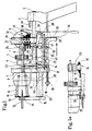
- a front wall 1 two parallel guide rods 2 are fixed placed, at the ends of a handle 3 is attached on the right.
- the one rotatable stripping head 5 stores.
- the stripping head will via a shaft 6 and a toothed disk 7 and one, not shown Engine - e.g. via a toothed pinion or a toothed belt - driven.
- Wedge 8 controls knife levers 10 in the stripping head via rollers 5 are pivoted. It is from a push rod 9 displaceable against a compression spring, not shown. In order to are knives 11 which are attached to the free end of the knife lever 10 are adjustable in the radial direction to the cable 13.
- Centering jaws 12 are placed directly next to the knives 11 and can be brought to the cable surface with a second wedge (see EP-A1-195932).
- the carriage 4 is provided with a guide 33 for a storage module 34 trained template equipped and carries a fixed Guide for a pivot pin 28.
- a control lever 30 On the pivot pin 28 is a control lever 30 on the one hand and on the other hand a feed lever 29 attached.
- the feed lever 29 carries a feed blade 27, which by means of, not shown Spring pressed against feed teeth 49 of the memory module 34 is held (Fig. 3).
- a locking lever 25 is by means of a bearing pin 26 attached to the carriage 4 and like the feed blade 27 held in feed teeth 49 by means of a spring (not shown).
- a stop lever 24 pivotably mounted in the front plate 1 limits the path of the memory module in its pivoted-in position 34 and thus the slide 4. If it is swung out, it releases the path of the memory module as it moves in the basic position.
- the Values for diameter and length are provided by setting scales Setting spirals 32 (diameter), 37 (stripping length).
- Fig. 1 shows the stripping device at the moment when the finished stripped conductor is removable.
- the handle 22 is pressed by the user, the jaws 14 opened and the memory module 34 in its lowermost position because of one Driver pin 55 on the handle 22 of the locking lever 25 and the feed blade 27 from the feed teeth 49 of the memory module 34 is lifted off.
- Fig. 1a shows the simultaneous pivoting of the stop lever 24 by means of pin 23, which is connected to the jaw shaft 15 is. This gives the way for the memory module 34 in his Basic position free.
- the memory module 34 can be spring-loaded in its basic position not shown. For a user however, it is also possible to press the memory module 34 to slide into its basic position.
- the adjusting spiral 37 can also be used for setting the diameter be operated.
- Fig. 2 shows the stripping device at the moment when it was fitted with a new cable to be stripped.
- the Memory module 34 is in its lowest position, the control lever 30 pressed against the handle 3.
- a stop pin 38 for the limitation of the basic length is against a counterstop 39 created, and the knife 11 and centering jaws 12 are closed.
- the centering jaws 12 serve as a stop for the end of the cable ..
- By releasing the handle 22 the cable 13 is clamped by means of clamping jaws 14.
- 2a shows the setting process of the diameter stop 63 or the adjusting spiral with scale 32 for diameter adjustment for the first step.
- centering jaws and knives are arranged as shown. It could be appropriate Devices also without centering jaws or with centering jaws on the other side of the knife or on both sides arranged centering jaws may be provided.
- the illustrated Embodiment is just a good standard for conventional ones Coaxial cable.
- the invention is also not based on radially acting even limited rigid knives, but could also be rotatable, e.g. Use disc-shaped knives. In the case of non-rotating knives, especially form knives apply. Otherwise, EP-A1-297484 referenced in which a special knife variant is shown is also used in the context of the present invention could be.
- Fig. 3 shows the stripping device at the moment before the first Cut.
- the memory module 34 is supported with its longitudinal stop 44 against the stop lever 24 and thus limits the stripping length of the first section.
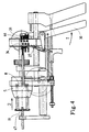
- Fig. 4 shows the stripping device at the moment when the knife 11 made the first cut.
- the stop edge 31 sits on the diameter stop 46 for the first depth of cut on (see Fig. 1a)
- FIG. 5 shows a special embodiment of the memory module 34 with adjustable stops. They are by grub screws 43 clampable.
- a memory module according to the invention is created, that flexible to the appropriate needs of the appropriate Cable can be adjusted.
- the invention is not restricted to adjustable memory modules, but also includes fixed (e.g. manufactured in plastic injection) memory modules, if necessary already supplied by the cable industry can. There are minor adjustment possibilities, apart from that from the memory module itself, still through - if available but not shown - setting options for the feelers between the tools and the memory module. Likewise, if necessary - to compensate for manufacturing tolerances - The stripping knife and centering jaws adjustable in their position.
- FIG. 6 Another special embodiment of the memory module is shown in Fig. 6 shown.
- the stop pins 54 push through one or two clamping plates 57, which e.g. out Spring steel are made.
- the hole in the clamping plate has practically no game.
- a compression spring 50 is supported against the body 51 of the memory module 34 and the spring-loaded Stop pin 54 in the stop direction. His stop face is widened and serves as a counterstop for the compression spring 50.
- Clamping springs 56 spring-loaded at one end the pressure plate 57, so that this with its bore the stop pin 54 misjudged, slightly bent inwards.
- the clamping plates are cylindrical Pin held spread in position.
- the left one Figure part refers to a cut along the line BB through the right part of the figure, which in turn is a cut through the left part of the figure along the section line AA.
Landscapes
- Removal Of Insulation Or Armoring From Wires Or Cables (AREA)
Description
- 1.
- Frontwand
- 2.
- Führungsstangen
- 3.
- Handgriff
- 4.
- Schlitten
- 5.
- Abisolierkopf
- 6.
- Welle
- 7.
- Zahnscheibe
- 8.
- Keil
- 9.
- Schubstange
- 10.
- Messerhebel
- 11.
- Messer
- 12.
- Zentrierbacken
- 13.
- Leiter zum Abisolieren
- 14.
- Spannbacken
- 15.
- Spannbackenwelle
- 16.
- Rollen
- 17.
- Rollenhebel
- 18.
- Spindel
- 19.
- Stellmutter
- 20.
- Druckfeder
- 21.
- Spreizkegel
- 22.
- Griffstück
- 23.
- Stift
- 24.
- Anschlaghebel
- 25.
- Riegelhebel
- 26.
- Lagerstift
- 27.
- Vorschubklinge
- 28.
- Drehbolzen
- 29.
- Vorschubhebel
- 30.
- Steuerhebel
- 31.
- Anschlagkante
- 32.
- Stellspirale für Länge
- 33.
- Führung
- 34.
- Speichermodul
- 35.
- Anschlagstift für Länge
Claims (16)
- Abisoliervorrichtung für mehrlagige Kabel (13), mit auf mehrere Schnitttiefen einstellbare Abisoliermesser (11) und einer Folgesteuerung (8) für die Schnitttiefenverstellung, dadurch gekennzeichnet, dass der Folgesteuerung (8) ein erster Tastfühler (9,24,39) zugeordnet ist, der anderenends direkt oder indirekt an einer Schablone (34) abstützbar ist, die wenigstens zwei unterschiedliche Abstützstufen (35,36,38;44) aufweist, wobei die Schablone (34) relativ zum Tastfühler (9,24,39) so verstellbar ist, dass in Abfolge die eine und dann die andere Abstützstufe (35,36,38;44) zum Eingriff kommt.
- Abisoliervorrichtung für mehrlagige Kabel (13), mit auf mehrere Abzugslängen einstellbare Abisoliermesser (11) und einer Folgesteuerung (8) für die Abzugslängenverstellung, dadurch gekennzeichnet, dass der Folgesteuerung (4,28,30) ein zweiter Tastfühler (24,39) zugeordnet ist, der anderenends direkt oder indirekt an einer Schablone (34) abstützbar ist, die wenigstens zwei unterschiedliche Abstützstufen (35,36,38;44) aufweist, wobei die Schablone (34) relativ zum Tastfühler (24,39) so verstellbar ist, dass in Abfolge die eine und dann die andere Abstützstufe (35,36,38;44) zum Eingriff kommt.
- Abisoliervorrichtung nach Anspruch 1 und 2.
- Abisoliervorrichtung nach Anspruch 3, dadurch gekennzeichnet, dass die Abstützstufen (35,36,38;44) für Schnitttiefe und Abzugslänge in einer gemeinsamen Schablone (34) integriert sind.
- Abisoliervorrichtung nach Anspruch 3, dadurch gekennzeichnet, dass die Abstützstufen (35,36,38;44) für Schnitttiefe und Abzugslänge an je einer getrennten Schablone (34) ausgebildet sind.
- Abisoliervorrichtung nach einem der vorhergehenden Ansprüche, dadurch gekennzeichnet, dass die Schablone einstückig ausgebildet ist, z.B. aus Metall gefräst und/oder in Kunststoffspritzguss gefertigt ist.
- Abisoliervorrichtung nach einem der vorhergehenden Ansprüche, dadurch gekennzeichnet, dass die Abstützstufen (35,36,38;44)an - relativ zueinander verstellbaren - Anschlagelementen, insbesondere Anschlagstiften (54) ausgebildet sind.
- Abisoliervorrichtung nach Anspruch 7, dadurch gekennzeichnet, dass die Anschlagstifte (54) gegenüber dem Schablonenkörper (51) mittels Schrauben (43) arretierbar sind.
- Abisoliervorrichtung nach Anspruch 7, dadurch gekennzeichnet, dass die Anschlagstifte (54) durch zur Einstellung lösbare Federklemmelemente (57) arretierbar sind.
- Abisoliervorrichtung nach einem der Ansprüche 7-9, dadurch gekennzeichnet, dass die Anschlagstifte 54 gegenüber dem Schablonenkörper in Anschlagrichtung federbelastet sind.
- Abisoliervorrichtung nach einem der vorhergehenden Ansprüche, dadurch gekennzeichnet, dass die Relativverschiebung der Schablone (34) klinkengesteuert ist.
- Abisoliervorrichtung nach einem der vorhergehenden Ansprüche, dadurch gekennzeichnet, dass wenigstens ein Tastfühler (24,39) ausschwenkbar ist, um die Wirkung der Schablone (34) aufzuheben und die Schablone rückzusetzen.
- Abisoliervorrichtung nach einem der vorhergehenden Ansprüche, dadurch gekennzeichnet, dass Spannzangen für das radiale Fixieren des Kabels (13) vorgesehen sind, die kurvengesteuert gegen eine Zugfeder (61) mittels Griffstück (22) nach Art eines Abzughahns gesteuert sind und vorzugsweise mit dem ausschwenkbaren Tastfühler (24,39) gekoppelt sind.
- Abisoliervorrichtung nach einem der vorhergehenden Ansprüche, dadurch gekennzeichnet, dass der Wirkungsbereich der Tastfühler über eine Spiralkurvensteuerung (32,37) mit Anzeige wählbar ist.
- Abisoliervorrichtung nach einem der vorhergehenden Ansprüche, dadurch gekennzeichnet, dass sie in einem einhändig tragbaren Gehäuse mit Handgriff (3) integriert ist.
- Abisoliervorrichtung nach einem der vorhergehenden Ansprüche, dadurch gekennzeichnet, dass die Abisoliermesser (11) an einem drehbaren Abisolierkopf (5) gehalten sind und durch einem Antrieb während des Einschneidens rotierbar sind.
Applications Claiming Priority (3)
| Application Number | Priority Date | Filing Date | Title |
|---|---|---|---|
| CH294697 | 1997-12-23 | ||
| CH294697 | 1997-12-23 | ||
| PCT/IB1998/002125 WO1999034493A1 (de) | 1997-12-23 | 1998-12-23 | Abisoliervorrichtung |
Publications (2)
| Publication Number | Publication Date |
|---|---|
| EP1042850A1 EP1042850A1 (de) | 2000-10-11 |
| EP1042850B1 true EP1042850B1 (de) | 2001-11-14 |
Family
ID=4245199
Family Applications (1)
| Application Number | Title | Priority Date | Filing Date |
|---|---|---|---|
| EP98963643A Expired - Lifetime EP1042850B1 (de) | 1997-12-23 | 1998-12-23 | Abisoliervorrichtung |
Country Status (5)
| Country | Link |
|---|---|
| EP (1) | EP1042850B1 (de) |
| JP (1) | JP2002500498A (de) |
| AU (1) | AU1885099A (de) |
| DE (1) | DE59802178D1 (de) |
| WO (1) | WO1999034493A1 (de) |
Cited By (1)
| Publication number | Priority date | Publication date | Assignee | Title |
|---|---|---|---|---|
| DE20310377U1 (de) * | 2003-07-05 | 2004-11-18 | Weidmüller Interface Gmbh & Co. | Zange mit einer Abisolierstation |
Families Citing this family (3)
| Publication number | Priority date | Publication date | Assignee | Title |
|---|---|---|---|---|
| CN1222296C (zh) | 1998-08-24 | 2005-10-12 | 村松乔 | 动脉硬化和ptca术后再狭窄的预防剂/治疗剂 |
| CN103346507B (zh) * | 2013-06-28 | 2018-02-02 | 浙江广为电器工具有限公司 | 一种旋转式电线剥皮机 |
| CN116799711B (zh) * | 2023-03-22 | 2025-10-17 | 西安领克数通信息技术有限公司 | 一种便携式手动剥线装置 |
Family Cites Families (2)
| Publication number | Priority date | Publication date | Assignee | Title |
|---|---|---|---|---|
| EP0195932B1 (de) * | 1985-02-22 | 1988-11-09 | Jiri Stepan | Abisoliervorrichtung |
| US4999910A (en) * | 1990-05-10 | 1991-03-19 | The Boeing Company | Rotary wire stripper and method of using |
-
1998
- 1998-12-23 WO PCT/IB1998/002125 patent/WO1999034493A1/de not_active Ceased
- 1998-12-23 DE DE59802178T patent/DE59802178D1/de not_active Expired - Fee Related
- 1998-12-23 EP EP98963643A patent/EP1042850B1/de not_active Expired - Lifetime
- 1998-12-23 JP JP2000527011A patent/JP2002500498A/ja active Pending
- 1998-12-23 AU AU18850/99A patent/AU1885099A/en not_active Abandoned
Cited By (2)
| Publication number | Priority date | Publication date | Assignee | Title |
|---|---|---|---|---|
| DE20310377U1 (de) * | 2003-07-05 | 2004-11-18 | Weidmüller Interface Gmbh & Co. | Zange mit einer Abisolierstation |
| US6895836B2 (en) | 2003-07-05 | 2005-05-24 | Weidmueller Interface Gmbh & Co. Kg | Pliers-type handtool having insulation removing means |
Also Published As
| Publication number | Publication date |
|---|---|
| DE59802178D1 (de) | 2001-12-20 |
| WO1999034493A1 (de) | 1999-07-08 |
| EP1042850A1 (de) | 2000-10-11 |
| AU1885099A (en) | 1999-07-19 |
| JP2002500498A (ja) | 2002-01-08 |
Similar Documents
| Publication | Publication Date | Title |
|---|---|---|
| DE69008411T2 (de) | Entmantelungsapparat für Koaxialkabel. | |
| DE68920497T3 (de) | Apparat zum stufenweisen Abisolieren von Draht. | |
| DE69500530T2 (de) | Dupliciermaschine,insbesonderes für flach und läserschlüsseln | |
| EP3093080B1 (de) | Matrizenwechsler mit daran angepasster wechselmatrize und matrizendom sowie verfahren zum entfernen und einsetzen der wechselmatrize | |
| CH683645A5 (de) | Abisoliervorrichtung für Glasfaserkabel. | |
| DE2929932A1 (de) | Drehtischvorrichtung zum schneiden von platten, profilen und aehnlichem mit einer kreissaege | |
| DE2416781C3 (de) | Abisolierzange | |
| DE2355339B2 (de) | Präzisionshaltevorrichtung für zylindrische Werkstücke | |
| DE1907803A1 (de) | Bohrer-Schleifgeraet | |
| EP0761029B1 (de) | Verfahren zum abisolieren eines isolierten drahtes oder kabels mit möglicherweise unrundem querschnitt und abisoliervorrichtung für das ausführen des verfahrens | |
| DE60001337T2 (de) | Bohrfutter | |
| DE10261968B4 (de) | Verfahren zur Herstellung eines Mitnehmerelements für einen Spanndorn | |
| EP1042850A1 (de) | Abisoliervorrichtung | |
| DE2113107A1 (de) | Vorrichtung zum Durchschneiden und teilweisen Abisolieren elektrischer Draehte oder Kabel | |
| EP0222112B1 (de) | Vorrichtung zum Abisolieren von Kabeln | |
| DE1925695B2 (de) | Manuell betätigbares Werkzeug zum Biegen und Schneiden von Stäben und Drähten | |
| DE2718973A1 (de) | Einstellvorrichtung fuer das musterstueck bei einer reproduktionsmaschine | |
| DE616771C (de) | Kegeldrehvorrichtung fuer den Querschlitten selbsttaetiger Drehbaenke | |
| DE2525896A1 (de) | Verstellbarer anschlag zum aufstellen eines zu bearbeitenden werkstuecks auf einer werkzeugmaschine | |
| DE2438854C2 (de) | Vorrichtung zum Abisolieren elektrischer Leiter | |
| DE2622566A1 (de) | Rohrabschneider zum ablaengen und gleichzeitigen anschraegen von rohren, insbesondere kunststoffrohren | |
| DE622350C (de) | Verfahren zur Herstellung von Gaufrierwalzen fuer Filme durch ein Raendelrad | |
| DE8814057U1 (de) | Abmantelungswerkzeug | |
| DE80425C (de) | ||
| DE2447263C3 (de) | Schlüsselfräsmaschiiie |
Legal Events
| Date | Code | Title | Description |
|---|---|---|---|
| PUAI | Public reference made under article 153(3) epc to a published international application that has entered the european phase |
Free format text: ORIGINAL CODE: 0009012 |
|
| 17P | Request for examination filed |
Effective date: 20000724 |
|
| AK | Designated contracting states |
Kind code of ref document: A1 Designated state(s): CH DE IT LI |
|
| RAP1 | Party data changed (applicant data changed or rights of an application transferred) |
Owner name: SCHLEUNIGER HOLDING AG |
|
| RIN1 | Information on inventor provided before grant (corrected) |
Inventor name: JIRI, STEPAN |
|
| GRAG | Despatch of communication of intention to grant |
Free format text: ORIGINAL CODE: EPIDOS AGRA |
|
| 17Q | First examination report despatched |
Effective date: 20001130 |
|
| GRAG | Despatch of communication of intention to grant |
Free format text: ORIGINAL CODE: EPIDOS AGRA |
|
| GRAG | Despatch of communication of intention to grant |
Free format text: ORIGINAL CODE: EPIDOS AGRA |
|
| GRAH | Despatch of communication of intention to grant a patent |
Free format text: ORIGINAL CODE: EPIDOS IGRA |
|
| GRAH | Despatch of communication of intention to grant a patent |
Free format text: ORIGINAL CODE: EPIDOS IGRA |
|
| GRAA | (expected) grant |
Free format text: ORIGINAL CODE: 0009210 |
|
| AK | Designated contracting states |
Kind code of ref document: B1 Designated state(s): CH DE IT LI |
|
| REG | Reference to a national code |
Ref country code: CH Ref legal event code: EP |
|
| REF | Corresponds to: |
Ref document number: 59802178 Country of ref document: DE Date of ref document: 20011220 |
|
| PLBE | No opposition filed within time limit |
Free format text: ORIGINAL CODE: 0009261 |
|
| STAA | Information on the status of an ep patent application or granted ep patent |
Free format text: STATUS: NO OPPOSITION FILED WITHIN TIME LIMIT |
|
| 26N | No opposition filed | ||
| PGFP | Annual fee paid to national office [announced via postgrant information from national office to epo] |
Ref country code: CH Payment date: 20021230 Year of fee payment: 5 |
|
| PGFP | Annual fee paid to national office [announced via postgrant information from national office to epo] |
Ref country code: DE Payment date: 20030106 Year of fee payment: 5 |
|
| PG25 | Lapsed in a contracting state [announced via postgrant information from national office to epo] |
Ref country code: LI Free format text: LAPSE BECAUSE OF NON-PAYMENT OF DUE FEES Effective date: 20031231 Ref country code: CH Free format text: LAPSE BECAUSE OF NON-PAYMENT OF DUE FEES Effective date: 20031231 |
|
| PG25 | Lapsed in a contracting state [announced via postgrant information from national office to epo] |
Ref country code: DE Free format text: LAPSE BECAUSE OF NON-PAYMENT OF DUE FEES Effective date: 20040701 |
|
| REG | Reference to a national code |
Ref country code: CH Ref legal event code: PL |
|
| PG25 | Lapsed in a contracting state [announced via postgrant information from national office to epo] |
Ref country code: IT Free format text: LAPSE BECAUSE OF NON-PAYMENT OF DUE FEES Effective date: 20051223 |