EP1040550B1 - Bürstenloser, elektronisch kommutierter motor - Google Patents
Bürstenloser, elektronisch kommutierter motor Download PDFInfo
- Publication number
- EP1040550B1 EP1040550B1 EP98965771A EP98965771A EP1040550B1 EP 1040550 B1 EP1040550 B1 EP 1040550B1 EP 98965771 A EP98965771 A EP 98965771A EP 98965771 A EP98965771 A EP 98965771A EP 1040550 B1 EP1040550 B1 EP 1040550B1
- Authority
- EP
- European Patent Office
- Prior art keywords
- motor
- accordance
- stator
- winding
- coil
- Prior art date
- Legal status (The legal status is an assumption and is not a legal conclusion. Google has not performed a legal analysis and makes no representation as to the accuracy of the status listed.)
- Revoked
Links
- 238000004804 winding Methods 0.000 claims abstract description 82
- 238000003825 pressing Methods 0.000 claims description 4
- 239000002184 metal Substances 0.000 claims description 2
- 238000001746 injection moulding Methods 0.000 claims 2
- 238000000034 method Methods 0.000 claims 2
- 230000007935 neutral effect Effects 0.000 claims 1
- 239000004020 conductor Substances 0.000 abstract description 5
- 238000004519 manufacturing process Methods 0.000 description 5
- 238000006073 displacement reaction Methods 0.000 description 4
- 238000003780 insertion Methods 0.000 description 4
- 230000037431 insertion Effects 0.000 description 4
- 238000005304 joining Methods 0.000 description 3
- 230000004323 axial length Effects 0.000 description 2
- 238000010586 diagram Methods 0.000 description 2
- 238000002485 combustion reaction Methods 0.000 description 1
- 238000001816 cooling Methods 0.000 description 1
- 238000011161 development Methods 0.000 description 1
- 230000018109 developmental process Effects 0.000 description 1
- 230000006698 induction Effects 0.000 description 1
- 238000002347 injection Methods 0.000 description 1
- 239000007924 injection Substances 0.000 description 1
- 238000009434 installation Methods 0.000 description 1
- 239000011810 insulating material Substances 0.000 description 1
- 238000003475 lamination Methods 0.000 description 1
- 239000002991 molded plastic Substances 0.000 description 1
- 230000005405 multipole Effects 0.000 description 1
- 238000004806 packaging method and process Methods 0.000 description 1
- 230000000737 periodic effect Effects 0.000 description 1
- 230000002093 peripheral effect Effects 0.000 description 1
- 125000006850 spacer group Chemical group 0.000 description 1
- 238000003860 storage Methods 0.000 description 1
- 238000005406 washing Methods 0.000 description 1
Images


Classifications
-
- H—ELECTRICITY
- H02—GENERATION; CONVERSION OR DISTRIBUTION OF ELECTRIC POWER
- H02K—DYNAMO-ELECTRIC MACHINES
- H02K29/00—Motors or generators having non-mechanical commutating devices, e.g. discharge tubes or semiconductor devices
-
- H—ELECTRICITY
- H02—GENERATION; CONVERSION OR DISTRIBUTION OF ELECTRIC POWER
- H02K—DYNAMO-ELECTRIC MACHINES
- H02K21/00—Synchronous motors having permanent magnets; Synchronous generators having permanent magnets
- H02K21/12—Synchronous motors having permanent magnets; Synchronous generators having permanent magnets with stationary armatures and rotating magnets
- H02K21/22—Synchronous motors having permanent magnets; Synchronous generators having permanent magnets with stationary armatures and rotating magnets with magnets rotating around the armatures, e.g. flywheel magnetos
-
- H—ELECTRICITY
- H02—GENERATION; CONVERSION OR DISTRIBUTION OF ELECTRIC POWER
- H02K—DYNAMO-ELECTRIC MACHINES
- H02K1/00—Details of the magnetic circuit
- H02K1/06—Details of the magnetic circuit characterised by the shape, form or construction
- H02K1/12—Stationary parts of the magnetic circuit
- H02K1/14—Stator cores with salient poles
- H02K1/146—Stator cores with salient poles consisting of a generally annular yoke with salient poles
- H02K1/148—Sectional cores
-
- H—ELECTRICITY
- H02—GENERATION; CONVERSION OR DISTRIBUTION OF ELECTRIC POWER
- H02K—DYNAMO-ELECTRIC MACHINES
- H02K3/00—Details of windings
- H02K3/04—Windings characterised by the conductor shape, form or construction, e.g. with bar conductors
- H02K3/12—Windings characterised by the conductor shape, form or construction, e.g. with bar conductors arranged in slots
-
- H—ELECTRICITY
- H02—GENERATION; CONVERSION OR DISTRIBUTION OF ELECTRIC POWER
- H02K—DYNAMO-ELECTRIC MACHINES
- H02K3/00—Details of windings
- H02K3/04—Windings characterised by the conductor shape, form or construction, e.g. with bar conductors
- H02K3/28—Layout of windings or of connections between windings
-
- H—ELECTRICITY
- H02—GENERATION; CONVERSION OR DISTRIBUTION OF ELECTRIC POWER
- H02K—DYNAMO-ELECTRIC MACHINES
- H02K3/00—Details of windings
- H02K3/46—Fastening of windings on the stator or rotor structure
- H02K3/52—Fastening salient pole windings or connections thereto
- H02K3/521—Fastening salient pole windings or connections thereto applicable to stators only
- H02K3/522—Fastening salient pole windings or connections thereto applicable to stators only for generally annular cores with salient poles
-
- H—ELECTRICITY
- H02—GENERATION; CONVERSION OR DISTRIBUTION OF ELECTRIC POWER
- H02K—DYNAMO-ELECTRIC MACHINES
- H02K2203/00—Specific aspects not provided for in the other groups of this subclass relating to the windings
- H02K2203/03—Machines characterised by the wiring boards, i.e. printed circuit boards or similar structures for connecting the winding terminations
-
- H—ELECTRICITY
- H02—GENERATION; CONVERSION OR DISTRIBUTION OF ELECTRIC POWER
- H02K—DYNAMO-ELECTRIC MACHINES
- H02K2203/00—Specific aspects not provided for in the other groups of this subclass relating to the windings
- H02K2203/09—Machines characterised by wiring elements other than wires, e.g. bus rings, for connecting the winding terminations
-
- H—ELECTRICITY
- H02—GENERATION; CONVERSION OR DISTRIBUTION OF ELECTRIC POWER
- H02K—DYNAMO-ELECTRIC MACHINES
- H02K2203/00—Specific aspects not provided for in the other groups of this subclass relating to the windings
- H02K2203/12—Machines characterised by the bobbins for supporting the windings
-
- Y—GENERAL TAGGING OF NEW TECHNOLOGICAL DEVELOPMENTS; GENERAL TAGGING OF CROSS-SECTIONAL TECHNOLOGIES SPANNING OVER SEVERAL SECTIONS OF THE IPC; TECHNICAL SUBJECTS COVERED BY FORMER USPC CROSS-REFERENCE ART COLLECTIONS [XRACs] AND DIGESTS
- Y10—TECHNICAL SUBJECTS COVERED BY FORMER USPC
- Y10S—TECHNICAL SUBJECTS COVERED BY FORMER USPC CROSS-REFERENCE ART COLLECTIONS [XRACs] AND DIGESTS
- Y10S310/00—Electrical generator or motor structure
- Y10S310/06—Printed-circuit motors and components
Definitions
- the invention relates to a brushless, electronically commutated motor specified in the preamble of claim 1.
- Electric motors increasingly in the foreground.
- This is Electric motors, which require the periodic switching of coils no longer by a commutator, but by electronic ones Switching devices is made.
- To the electronic Switching devices can, for. B. include appropriate sensors that determine when the stator and the rotor for the coils to be switched are in a circuit-favorable or circuit-requiring relative position. It goes without saying that the electronic switching devices also ensure this must that the power supply to the or the respective coils in the just matching current direction.
- Permanent magnets are used either for the stator poles or for the rotor poles have been.
- Permanent magnets offer a number of advantages, such as lack of power consumption, small size and easy manufacture and Assembly.
- Such electric motors are used today on many technical Areas used, such. B. also in the automotive industry as a drive motor for Radiator fan or servo devices. Especially along the direction of travel built-in internal combustion engines in motor vehicles is the installation space for an electrically operated fan for cooling the cooler very limited.
- Conventional permanent magnet motors can be used because of their large axial Do not use length.
- DE 35 42 542 A1 is a disk storage drive with a brushless drive motor known, the one provided with a winding Stator and a coaxially encompassing the stator to form an air gap Has outer rotor with a permanent magnetic motor magnet. There the winding coils are connected in series in each winding strand, a higher current also flows through the winding coils. This in turn causes a current displacement, which leads to poorer efficiency. Furthermore, this prior art has only two pairs of poles, whereby due to the higher cogging torque, higher noises are also generated.
- DE-AS 1 613 005 shows a collectorless DC motor with a single or multi-pole pair permanent magnet rotor and with several stationary winding strands, one after the other by means of a control circuit can be connected to a constant direct current source.
- This is advantageous Motor shaft formed directly as a sound source of a tape recorder, this Tonwelle on different speeds to achieve different Belt speeds can be switched.
- the winding coils are with this Motor not in the slots of the stator and are therefore not subject to Current displacement.
- German patent application DE 36 38 228 A1 discloses a Leg plate package for a dynamoelectric machine and in particular a Method of manufacturing a salient pole motor with an electronically commutated motor to drive a washing machine. hereby is known a circuit board with the ends of concentrated windings connected is. These windings are preselected in at least one Sequence electronically commutated to excite the electric motor cause. In particular, a circuit board with conductor tracks for Connection of the individual coils used.
- EP-A-777312 discloses a stator for electric motors which from a stator laminated core, stator windings and one on one end of the Stator lamination stack arranged circuit arrangement for the stator windings consists.
- a brushless electric motor is known from EP-A-777312, in which a circuit board with busbars is provided for connecting the individual winding coils, and each winding strand consists of a plurality of winding coils connected in parallel
- no busbar is provided for connecting the star point of a star connection to the ends of all winding coils.
- the invention has for its object a brushless, electronic commutated motor in such a way that it improves at an axial Flat design, simple manufacture and low weight and one has high efficiency. This object is achieved by the in claim 1 marked features solved.
- the EC motor according to the invention has the desired windings Advantage that an overlap of the winding heads is avoided, which is affects in particular on a small axial length.
- Figure 1 shows a partial section through a brushless, electronic commutated motor, also called EC motor 1, which in particular as Drive motor for a motor vehicle fan drive with a permanent magnet 3 having outer rotor 5, in which a stator 7 with three by 120 ° offset winding strands 9, 11, 13 is arranged. Every winding strand 9, 11, 13 has z. B. 4 connected in parallel Winding coils 15, 17, 19, 21, 23, 25, 27, 29, 31, 33, 35, 37, which in 12 Winding slots 39, 41, 43, 45, 47, 49, 51, 53, 55, 57, 59, 61 of the stator 7 are wrapped. Since the outer rotor 5 has four pole pairs, the coil width is each winding coil 15 - 37 smaller than the pole pitch.
- the coil width of the winding coils 15 - According to FIG. 7, 37 is in particular 2/3 of the pole pitch. This shows that any overlap of winding heads of the winding coils 15 - 37 avoided becomes. Due to the low height of the winding heads, the axial length of the EC motor 1 reduced.
- FIG. 8 shows that each winding strand 9, 11, 13 from z. B. four in parallel switched winding coils 15 - 37.
- the phase current is distributed over several parallel current branches, whereby the Conductor cross section of a winding strand 9, 11, 13 can be reduced so far can that no longer several parallel layers in a winding slot 39 - 61 become necessary. This causes a current displacement in the Winding slots 39 - 61, as is known from asynchronous rotors, is reduced.
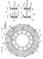
- winding strands 9, 11, 13 is a circuit board 63 provided from an insulating material, in the surface 65 four Busbars 67, 69, 71, 73 are embedded.
- the fourth busbar 73 is used to connect the star point 75 with the Ends 77 of all winding coils 15 - 37 of the three winding strands 9, 11, 13.
- the circuit board 63 with the four busbars 67, 69, 71, 73 is according to FIG. 1 together with the stator 7 connected to a motor bracket 79 and enables automation of production.
- the stator 7 advantageously consists of a hollow cylindrical yoke 81 with its outer peripheral surface 83 longitudinal stator poles 85, 87, 89, 91, 93, 95, 97, 99, 101, 103, 105, 107, which by means of a press connection with the yoke part 81 are firmly connected.
- This stator poles 85-107 and the yoke 81 consist of punched sheet metal parts, which are punched by packaging be held together.
- stator poles 85 - 107 The fixed connection of the stator poles 85 - 107 with the rear part 81 achieved in the simplest way that the stator poles 85-107 at their Pole teeth 109, 111, 113, 115, 117, 119, 121, 123, 125, 127, 129, 131 opposite ends with insert shoes 133, 135, 137, 139, 141, 143, 145, 147, 149, 151, 153, 155 are provided, which in guide grooves 157 in the Surface 83 of the yoke 81 can be pressed. To this end have the insertion shoes 133-155 of the stator poles 85-107 and the Guide grooves 157 in the yoke 81 a dovetail-like Shape up.
- Pressing the insert shoes 133-155 into the guide grooves 157 of the Inference part 81 is facilitated in that the joining line 159 according to 4 between the insert shoes 133-155 and the guide grooves 157 partially has an air gap. This makes a press fit Insert shoes 133 - 155 in the guide grooves 157 only in some areas achieved. This reduces press-in forces and deformations.
- the joining line 159 is between the stator poles 85-107 and the Inference part 81 arranged asymmetrically to the stator pole axes 161, whereby the insertion of the stator poles 85 - 107 into the guide grooves 157 of the Inference part 81 is only ever possible from one side. This is related on any existing burrs on the stator poles 85 - 107 and / or the inference part 81 advantageous.
- the asymmetrical arrangement of the joining line 159 is very simple achieved in that the insertion shoes 133-155 of the stator poles 85-107 the stator pole axes 161 have eccentrically arranged recesses 163.
- the recesses 163 are axially aligned Elevations 169 in the guide grooves 157 can be pushed on in a form-fitting manner.
- the stator poles 85-107 are advantageously in the guide grooves 157 of the Inference part 81 is only pressed in when the pole core 171 with a Provide coil former 173 and the associated one on it Stator winding coil 15 - 37 is wound. This has the advantage that layer winding with a high slot filling factor is possible. Furthermore is hereby a smaller slot slot can be used than this when winding through the Slot slots would be possible.
- the coil former 173 can be made of Injection molded plastic parts, which are on the insertion shoes 133 - 155 the pole cores 171 of the stator poles 85-107 are arranged in a fixed manner.
- the EC motor according to the invention is characterized by a flat axial Design and a low-noise run and enables automatic Production.
- the invention is not restricted to the exemplary embodiment described. So can the outer rotor 5 a different number of pole pairs and the stator 7 a accordingly changed number of winding coils connected in parallel per Have winding strand. Furthermore, the EC motor can be used as Drive motor also in blowers or in other technical devices be used.
Landscapes
- Engineering & Computer Science (AREA)
- Power Engineering (AREA)
- Insulation, Fastening Of Motor, Generator Windings (AREA)
- Windings For Motors And Generators (AREA)
- Iron Core Of Rotating Electric Machines (AREA)
- Permanent Magnet Type Synchronous Machine (AREA)
- Brushless Motors (AREA)
- Permanent Field Magnets Of Synchronous Machinery (AREA)
Abstract
Description
Auch hierbei ist keine Stromschiene zum Verbinden des Sternpunktes einer Sternschaltung mit den Enden aller Wicklungsspulen vorgesehen.
Es zeigen:
- Figur 1
- einen Schnitt durch einen EC-Motor,
- Figur 2
- eine Draufsicht auf einen Statorpol,
- Figur 3
- eine Draufsicht auf einen Spulenkörper,
- Figur 4
- einen Statorpol mit einem Spulkörper und einer Wicklung,
- Figur 5
- eine Draufsicht auf ein Rückschlußteil des Stators,
- Figur 6
- eine Draufsicht auf den Stator und Läufer,
- Figur 7
- ein Wicklungsschema eines EC-Motors mit 12 Wicklungsnuten,
- Figur 8
- ein Wicklungsschema für einen 12-nutigen Stator mit vier Stromschienen,
- Figur 9
- eine Draufsicht auf eine Schaltplatte mit vier Stromschienen und
- Figur 10 - 13
- Einzelheiten aus Figur 9
Claims (16)
- Bürstenloser, elektronisch kommutierter Motor, insbesondere als Antriebsmotor für einen Kfz- Lüfterantrieb mit einem permanentmagnetischen Außenrotor, in dem ein Stator mit drei um 120°el versetzten Wickhmgssttängen angeordnet ist, wobei 0,5 Spulen je Pol und Strang gewickelt sind und jeder Wickhmgsstrang aus mehreren Wicklungsspulen besteht, deren Spulenweite kleiner als die Polteilung ist und die in Wicklungsnuten des Stators eingelegt sind, wobei jeder Wicklungsstrang aus mehreren parallel geschalteten Wicklungsspulen (15, 17, 19, 21, 23, 25, 27, 29, 31, 33, 35, 37) besteht und wobei eine Schaltplatte (63) mit Stromschienen (67, 69, 71, 73) zur Verbindung der einzelnen Wicklungsspulen (15, 17, 19, 21, 23, 25, 27, 29, 31, 33, 35, 37) vorgesehen ist, dadurch gekennzeichnet, daß die Schaltplatte (63) vier Stromschienen (67, 69, 71, 73) aufweist, von denen jedem der drei Wicklungsstränge (9, 11, 13) je eine Stromschiene (67,69, 71) zum Verbinden der Anfänge der parallel geschalteten Wicklungsspulen (15 - 37) zugeordnet ist, und daß die vierte Stromschiene (73) zum Verbinden des Sternpunktes (75) mit den Enden (77) aller Wicklungsspulen (15 - 37) der drei Wicklungsstränge (9, 11, 13) dient und daß der Außenrotor (5) mindestens p = 3 Polpaare aufweist.
- Motor nach Anspruch 1, dadurch gekennzeichnet, daß jeder Wicklungsstrang (9, 11, 13) aus vier parallel geschalteten Wicklungsspulen (15, 17,19, 21, 23, 25, 27, 29, 31, 33, 35, 37) besteht
- Motor nach Anspruch 1 oder 2, dadurch gekennzeichnet, daß die Spulenweite jeder Wicklungsspule (15, 17, 19, 21, 23, 25, 27, 29, 31, 33, 35, 37) 2/3 der Polteilung beträgt.
- Motor nach Anspruch 1, 2, oder 3, dadurch gekennzeichnet, daß in jeder Wicklungsnut (39, 41, 43, 45, 47, 49, 51, 53, 55, 57, 59, 61) je eine Spulenseite von zwei unterschiedlichen Wicklungssträngen (9, 11, 13) angeordnet ist.
- Motor nach einem der vorhergehenden Ansprüche, dadurch gekennzeichnet, daß der Stator (7) aus einem hohlzylinderförmigen Rückschlußteil (81) mit auf dessen Außemmfangsfläche (83) in Längsrichtung angeordneten Statorpolen (85, 87, 89, 91, 93, 95, 97, 99, 101, 103, 105, 107) besteht, welche mittels einer Preßverbindung mit dem Rückschlußteil (81) fest verbunden sind.
- Motor nach Anspruch 5, dadurch gekennzeichnet, daß die Statorpole (85 - 107) und das Rückschlußteil (81) aus gestanzten Blechteilen bestehen.
- Motor nach Anspruch 5 oder 6, dadurch gekennzeichnet, daß die Statorpole (85 - 107) an ihren Polzähnen (109 - 131) abgewandten Enden mit Einsteckschuhen (133 - 155) versehen sind, welche in Führungsmiten (157) in der Oberfläche (83) des Rückschlußteiles (81) einpreßbar sind.
- Motor nach Anspruch 7, dadurch gekennzeichnet, daß die Einsteckschuhe (133 - 155) der Statorpole (85 - 107) und die Führungsnuten (157) eine schwalbenschwanzähnliche Form aufweisen.
- Motor nach Anspruch 8, dadurch gekennzeichnet, daß die Fügelinie 8159) zwischen den Einsteckschuhen (133 - 155) und den Führungsnuten (157) teilweise einen Luftspalt aufweisen, derart, daß ein Preßsitz der Einsteckschuhe (133 - 155) in den Führungsnuten (157) nur in Teilbereichen erfolgt.
- Motor nach Anspruch 7,8 oder 9, dadurch gekennzeichnet, daß die Fügelinie (159) zwischen den Statorpolen (85 - 107) und dem Rückschlußteil (81) unsymetrisch zu der Statorpolachse (161) ist
- Motor nach Anspruch 10, dadurch gekennzeichnet, daß die Einsteckschuhe (133 - 155) der Statorpole (85 -107) zu den Statorpolachsen (161) exzentrisch angeordnete Vertiefungen (163) aufweisen, die beim Einpressen der Statorpole (85 - 107) in die Führungsnuten (167) des Rückschlußteiles (81) auf axial ausgerichtete Erhöhungen (169) in den Führungsnuten aufschiebbar sind.
- Motor nach einem der vorhergehenden Ansprüche, dadurch gekennzeichnet, daß auf den Polkernen (171) der Statorpole (85 - 107) Spulenkörper (173) für die Statorwicklungen (15 - 37) angeordnet sind, wobei die Statorwickhmgen (15 - 37) vor dem Zusammenfügen der Statorpole (85 - 107) mit dem Rückschlußteil (81) auf die Spulenkörper (173) aufwickelbar sind.
- Motor nach Anspruch 12, dadurch gekennzeichnet, daß die Spulenkörper (173) aus Kunststoffspritzteilen bestehen, welche über die Einsteckschuhe (133 - 155) auf die Polkerne (171) der Statorpole (85 - 107) aufschiebbar sind.
- Motor nach Anspruch 12, dadurch gekennzeichnet, daß die Spulenkörper (173) durch Umspritzen der Polkerne (171) auf den Statorpolen (85 - 107) fest angeordnet sind.
- Motor nach einem der vorhergehenden Ansprüche, dadurch gekennzeichnet, daß der Rotor (5) 4 Polpaare und jeder Wicklungsstrang (9, 11, 13, ) 4 parallel geschaltete Wicklungsspulen (15 -37) für einen 12-nutigen Stator aufweist.
- Motor nach einem der vorhergehenden Ansprüche, dadurch gekennzeichnet, daß der Motorflansch (79) in Strömungsrichtung der Luft vornliegend angeordnet ist, so daß Befestigungsstrebe und Luftführung (Zarge) aus einem Teil bestehen und platzsparend ausgebildet sind.
Applications Claiming Priority (3)
| Application Number | Priority Date | Filing Date | Title |
|---|---|---|---|
| DE19757136 | 1997-12-20 | ||
| DE19757136A DE19757136A1 (de) | 1997-12-20 | 1997-12-20 | Bürstenloser, elektrisch kommutierter Motor |
| PCT/EP1998/007917 WO1999033157A1 (de) | 1997-12-20 | 1998-12-05 | Bürstenloser, elektronisch kommutierter motor |
Publications (2)
| Publication Number | Publication Date |
|---|---|
| EP1040550A1 EP1040550A1 (de) | 2000-10-04 |
| EP1040550B1 true EP1040550B1 (de) | 2004-02-11 |
Family
ID=7852917
Family Applications (1)
| Application Number | Title | Priority Date | Filing Date |
|---|---|---|---|
| EP98965771A Revoked EP1040550B1 (de) | 1997-12-20 | 1998-12-05 | Bürstenloser, elektronisch kommutierter motor |
Country Status (10)
| Country | Link |
|---|---|
| US (1) | US6472783B1 (de) |
| EP (1) | EP1040550B1 (de) |
| JP (1) | JP2001527376A (de) |
| KR (1) | KR20010015887A (de) |
| CN (1) | CN1282457A (de) |
| BR (1) | BR9813725A (de) |
| CA (1) | CA2315755A1 (de) |
| DE (2) | DE19757136A1 (de) |
| ES (1) | ES2216347T3 (de) |
| WO (1) | WO1999033157A1 (de) |
Cited By (2)
| Publication number | Priority date | Publication date | Assignee | Title |
|---|---|---|---|---|
| US11837926B2 (en) | 2020-12-23 | 2023-12-05 | Black & Decker, Inc. | Brushless DC motor with stator teeth having multiple parallel sets of windings |
| US11984771B2 (en) | 2018-03-02 | 2024-05-14 | Black & Decker Inc. | Circuit board for connecting motor windings |
Families Citing this family (28)
| Publication number | Priority date | Publication date | Assignee | Title |
|---|---|---|---|---|
| DE19953291A1 (de) * | 1999-11-05 | 2001-07-19 | Mannesmann Sachs Ag | Wickelzahn zur Aufnahme einer Wicklung für den Magnetkreis eines elektro-magneto-mechanischen Wandlers, Blechpaket sowie elektro-magneto-mechanischer Wandler |
| DE20002284U1 (de) * | 2000-02-09 | 2001-06-13 | ebm Werke GmbH & Co., 74673 Mulfingen | Wechselstrom-Synchronmotor |
| JP2001275325A (ja) * | 2000-03-27 | 2001-10-05 | Honda Motor Co Ltd | 電動パワーステアリング装置 |
| DE10063619B4 (de) | 2000-12-20 | 2010-02-18 | Trw Automotive Electronics & Components Gmbh & Co. Kg | Antriebseinheit für Gebläse in Fahrzeugen |
| US6583530B2 (en) * | 2001-02-20 | 2003-06-24 | Chun-Pu Hsu | Composite stator structure having corresponding concave embedding receiving grooves and arc-shaped teeth surfaces |
| DE50214040D1 (de) * | 2001-03-09 | 2010-01-14 | Temic Auto Electr Motors Gmbh | Wicklungsaufbau für elektrische maschine sowie verfahren zur herstellung derselben |
| JP2003018773A (ja) * | 2001-06-28 | 2003-01-17 | Sankyo Seiki Mfg Co Ltd | コア付きモータ |
| JP2003079079A (ja) * | 2001-09-03 | 2003-03-14 | Honda Motor Co Ltd | 回転電機の集配電リング |
| KR100439199B1 (ko) * | 2001-11-29 | 2004-07-07 | (주)지엔더블유테크놀러지 | 병렬결선 구조를 가진 무브러시 직류 전동기 및 그 제어회로 |
| AU2002361019A1 (en) * | 2002-01-22 | 2003-09-02 | Ebm-Papst St. Georgen Gmbh & Co. Kg | Stator assembly |
| DE10257579B4 (de) * | 2002-12-09 | 2008-06-12 | Dorma Gmbh + Co. Kg | Linearantrieb, insbesondere für eine Schiebetür oder dergleichen |
| JP3733120B2 (ja) * | 2002-12-27 | 2006-01-11 | 穩正企業股▲ふん▼有限公司 | モータの組合せ式固定子構造 |
| EP1810388B1 (de) * | 2004-11-10 | 2014-04-23 | ebm-papst St. Georgen GmbH & Co. KG | Elektromotor |
| JP4993883B2 (ja) * | 2005-07-20 | 2012-08-08 | ヤマハ発動機株式会社 | 回転電機及び電動車椅子 |
| JP4712465B2 (ja) * | 2005-07-20 | 2011-06-29 | ヤマハ発動機株式会社 | 回転電機及び電動車椅子 |
| JP4726564B2 (ja) * | 2005-07-20 | 2011-07-20 | ヤマハ発動機株式会社 | 回転電機及び電動車椅子 |
| GB0616162D0 (en) | 2006-08-15 | 2006-09-20 | Whiteley Graham | Compact rotary actuator |
| US7671495B2 (en) * | 2006-11-20 | 2010-03-02 | Asmo Co., Ltd. | Armature and motor |
| DE102006061699A1 (de) * | 2006-12-28 | 2008-07-03 | Robert Bosch Gmbh | Statorwicklungsanordnung für einen Synchronmotor mit reduziertem Bremsmoment im Fehlerfall |
| DE202008012191U1 (de) * | 2008-09-15 | 2008-11-27 | Geiger Engineering | Elektrisches Antriebssystem |
| JP5478117B2 (ja) | 2009-05-21 | 2014-04-23 | アスモ株式会社 | モータ |
| EP2476189A1 (de) * | 2009-09-08 | 2012-07-18 | Green Ray Technologies LLC | Busschienenmodul für eine elektrische maschine |
| CN102647033A (zh) * | 2011-02-16 | 2012-08-22 | 苏州工业园区泰格电子科技有限公司 | 一种定子和由其构成的无刷电机及其绕线方法 |
| CN105298878B (zh) * | 2015-11-23 | 2019-03-29 | 赵国鹏 | 磁悬浮变频机扇一体机 |
| DE102018106461A1 (de) * | 2018-03-20 | 2019-09-26 | Schaeffler Technologies AG & Co. KG | Verschaltung von "n"-Stromschienen in einem Elektromotor |
| WO2019246604A1 (en) * | 2018-06-23 | 2019-12-26 | Gabrys Christopher W | High efficiency electronically commutated motor |
| CN110971016A (zh) * | 2018-09-29 | 2020-04-07 | 上海电驱动股份有限公司 | 一种外转子型轮毂电机的定子 |
| CN115378154B (zh) * | 2022-09-02 | 2025-11-25 | 航天科工智能机器人有限责任公司 | 一种定子结构、外转子电机及定子绕组的固定方法 |
Family Cites Families (13)
| Publication number | Priority date | Publication date | Assignee | Title |
|---|---|---|---|---|
| DE1613005B2 (de) * | 1967-03-18 | 1971-09-02 | Gebr Buhler Nachfolger GmbH, 8500 Nürnberg | Kollektorloser gleichstrommotor |
| CA1109916A (en) * | 1977-09-21 | 1981-09-29 | Yoshio Kishi | Stator yoke for electrical apparatus |
| SE428088B (sv) | 1981-10-14 | 1983-06-06 | Meteve Ab | Troakar |
| DE3331194A1 (de) * | 1983-08-30 | 1985-03-07 | Ebm Elektrobau Mulfingen Gmbh & Co, 7119 Mulfingen | Kollektorloser gleichstrommotor mit dreistraengiger, ungesehnter statorwicklung |
| JPH0782699B2 (ja) * | 1984-06-01 | 1995-09-06 | パプスト ライセンシング ゲーエムベーハー | デイスク駆動装置 |
| US4847526A (en) | 1985-07-11 | 1989-07-11 | Nippon Ferrofluidics Corporation | Variant-pole electric motor |
| US4712035A (en) * | 1985-11-12 | 1987-12-08 | General Electric Company | Salient pole core and salient pole electronically commutated motor |
| JPS62165393A (ja) * | 1986-01-16 | 1987-07-21 | 三洋電機株式会社 | 混成集積回路基板 |
| KR940001176B1 (ko) * | 1990-07-19 | 1994-02-16 | 가부시끼가이샤 도시바 | 3상 전기자 권선 |
| WO1993001644A1 (fr) * | 1991-07-11 | 1993-01-21 | Secoh Giken, Inc. | Moteur a courant alternatif sans noyau plat |
| JP2742183B2 (ja) * | 1992-09-10 | 1998-04-22 | 株式会社リコー | ブラシレスモータ |
| JP3616406B2 (ja) | 1994-04-22 | 2005-02-02 | 日本電産株式会社 | スピンドルモータ |
| DE19544830A1 (de) * | 1995-12-01 | 1997-06-05 | Mulfingen Elektrobau Ebm | Stator für Elektromotoren |
-
1997
- 1997-12-20 DE DE19757136A patent/DE19757136A1/de not_active Ceased
-
1998
- 1998-12-05 ES ES98965771T patent/ES2216347T3/es not_active Expired - Lifetime
- 1998-12-05 WO PCT/EP1998/007917 patent/WO1999033157A1/de not_active Ceased
- 1998-12-05 EP EP98965771A patent/EP1040550B1/de not_active Revoked
- 1998-12-05 KR KR1020007006806A patent/KR20010015887A/ko not_active Withdrawn
- 1998-12-05 CA CA002315755A patent/CA2315755A1/en not_active Abandoned
- 1998-12-05 BR BR9813725-5A patent/BR9813725A/pt not_active Application Discontinuation
- 1998-12-05 US US09/581,900 patent/US6472783B1/en not_active Expired - Fee Related
- 1998-12-05 DE DE59810764T patent/DE59810764D1/de not_active Revoked
- 1998-12-05 CN CN98812447A patent/CN1282457A/zh active Pending
- 1998-12-05 JP JP2000525961A patent/JP2001527376A/ja active Pending
Cited By (5)
| Publication number | Priority date | Publication date | Assignee | Title |
|---|---|---|---|---|
| US11984771B2 (en) | 2018-03-02 | 2024-05-14 | Black & Decker Inc. | Circuit board for connecting motor windings |
| US12413119B2 (en) | 2018-03-02 | 2025-09-09 | Black & Decker Inc. | Power tool |
| US11837926B2 (en) | 2020-12-23 | 2023-12-05 | Black & Decker, Inc. | Brushless DC motor with stator teeth having multiple parallel sets of windings |
| US12088160B2 (en) | 2020-12-23 | 2024-09-10 | Black & Decker Inc. | Brushless DC motor with circuit board for winding interconnections |
| US12107468B2 (en) | 2020-12-23 | 2024-10-01 | Black & Decker Inc. | Brushless DC motor having high power density for power tool |
Also Published As
| Publication number | Publication date |
|---|---|
| CN1282457A (zh) | 2001-01-31 |
| CA2315755A1 (en) | 1999-07-01 |
| DE19757136A1 (de) | 1999-06-24 |
| US6472783B1 (en) | 2002-10-29 |
| BR9813725A (pt) | 2000-10-10 |
| ES2216347T3 (es) | 2004-10-16 |
| JP2001527376A (ja) | 2001-12-25 |
| WO1999033157A1 (de) | 1999-07-01 |
| DE59810764D1 (de) | 2004-03-18 |
| EP1040550A1 (de) | 2000-10-04 |
| KR20010015887A (ko) | 2001-02-26 |
Similar Documents
| Publication | Publication Date | Title |
|---|---|---|
| EP1040550A1 (de) | Bürstenloser, elektronisch kommutierter motor | |
| EP0962041B1 (de) | Elektrische maschine mit einer einzelpolwicklung | |
| DE10128769B4 (de) | Elektrischer Motor | |
| DE69834685T2 (de) | Elektrodynamische drehende Permanentmagnetmaschine mit konzentrierter Statorwicklung | |
| EP1062720B1 (de) | Schaltungsanordnung zum verschalten von statorwicklungen eines bürstenlosen, elektronisch kommutierten motors | |
| DE102008023923B4 (de) | Stator, Verfahren zur Herstellung von Statorsegmenten, Verfahren zur Herstellung von einem Stator | |
| EP0394527B1 (de) | Heteropolar erregte Synchronmaschine | |
| DE10213743A1 (de) | Stator für Elektromotoren mit Wicklungs-Verschaltungsanordnung | |
| DE19818433A1 (de) | Gleichstrommotor und Verfahren zur Herstellung desselben | |
| EP2162971B1 (de) | Stator mit isolierung für einen elektromotor und isolierung für einen stator sowie elektrowerkzeugmaschine | |
| WO2008071147A2 (de) | Elektrische maschine und verfahren zum herstellen einer solchen | |
| DE102010030877A1 (de) | Steckbarer Polzahn | |
| DE102011053609A1 (de) | Drehende elektrische Maschine | |
| EP2026450B1 (de) | Elektrische Maschine mit einer Wicklung zur Erzeugung eines Drehfeldes und Verfahren zur Herstellung der Wicklung | |
| WO2005034308A1 (de) | Ständer für eine elektrische maschine | |
| DE102021122979A1 (de) | Wicklung für ein Aktivteil einer elektrischen Maschine, Aktivteil sowie elektrische Maschine | |
| DE4124425B4 (de) | Kollektorloser Gleichstrommotor mit verbesserter Drehmomentwelligkeit | |
| DE102006048967A1 (de) | Stator für eine elektrische Maschine | |
| WO2006103144A1 (de) | Elektrische maschine mit symmetrischen teilspulen | |
| DE102021127073A1 (de) | Rotor mit Querverbindern, elektrische Maschine sowie Verfahren zum Herstellen eines Rotors | |
| DE2855987A1 (de) | Gleichstrommotor mit zwei verschieden grossen arbeitsdrehzahlen | |
| DE9010895U1 (de) | Kollektorloser Gleichstrommotor mit verbesserter Drehmomentwelligkeit | |
| WO2016162128A1 (de) | Herstellungsverfahren einer wicklung um einen ausspringenden pol für eine synchronmaschine | |
| DE102021003736A1 (de) | Elektronisch kommutierter Elektromotor | |
| DE102016221595A1 (de) | Stator eines Elektromotors und Elektromotor |
Legal Events
| Date | Code | Title | Description |
|---|---|---|---|
| PUAI | Public reference made under article 153(3) epc to a published international application that has entered the european phase |
Free format text: ORIGINAL CODE: 0009012 |
|
| 17P | Request for examination filed |
Effective date: 20000520 |
|
| AK | Designated contracting states |
Kind code of ref document: A1 Designated state(s): DE ES FR GB IT SE |
|
| 17Q | First examination report despatched |
Effective date: 20030129 |
|
| GRAP | Despatch of communication of intention to grant a patent |
Free format text: ORIGINAL CODE: EPIDOSNIGR1 |
|
| GRAS | Grant fee paid |
Free format text: ORIGINAL CODE: EPIDOSNIGR3 |
|
| GRAA | (expected) grant |
Free format text: ORIGINAL CODE: 0009210 |
|
| AK | Designated contracting states |
Kind code of ref document: B1 Designated state(s): DE ES FR GB IT SE |
|
| REG | Reference to a national code |
Ref country code: GB Ref legal event code: FG4D Free format text: NOT ENGLISH |
|
| GBT | Gb: translation of ep patent filed (gb section 77(6)(a)/1977) |
Effective date: 20040211 |
|
| REF | Corresponds to: |
Ref document number: 59810764 Country of ref document: DE Date of ref document: 20040318 Kind code of ref document: P |
|
| REG | Reference to a national code |
Ref country code: SE Ref legal event code: TRGR |
|
| RAP2 | Party data changed (patent owner data changed or rights of a patent transferred) |
Owner name: TEMIC AUTOMOTIVE ELECTRIC MOTORS GMBH |
|
| REG | Reference to a national code |
Ref country code: ES Ref legal event code: FG2A Ref document number: 2216347 Country of ref document: ES Kind code of ref document: T3 |
|
| ET | Fr: translation filed | ||
| PLBQ | Unpublished change to opponent data |
Free format text: ORIGINAL CODE: EPIDOS OPPO |
|
| PLBI | Opposition filed |
Free format text: ORIGINAL CODE: 0009260 |
|
| PLAX | Notice of opposition and request to file observation + time limit sent |
Free format text: ORIGINAL CODE: EPIDOSNOBS2 |
|
| 26 | Opposition filed |
Opponent name: WILO AG Effective date: 20041111 |
|
| PLBB | Reply of patent proprietor to notice(s) of opposition received |
Free format text: ORIGINAL CODE: EPIDOSNOBS3 |
|
| PLAB | Opposition data, opponent's data or that of the opponent's representative modified |
Free format text: ORIGINAL CODE: 0009299OPPO |
|
| R26 | Opposition filed (corrected) |
Opponent name: WILO AG/PIERBURG GMBH Effective date: 20041111 |
|
| PGFP | Annual fee paid to national office [announced via postgrant information from national office to epo] |
Ref country code: SE Payment date: 20061213 Year of fee payment: 9 |
|
| PGFP | Annual fee paid to national office [announced via postgrant information from national office to epo] |
Ref country code: DE Payment date: 20061218 Year of fee payment: 9 |
|
| PGFP | Annual fee paid to national office [announced via postgrant information from national office to epo] |
Ref country code: GB Payment date: 20061221 Year of fee payment: 9 |
|
| PGFP | Annual fee paid to national office [announced via postgrant information from national office to epo] |
Ref country code: ES Payment date: 20061228 Year of fee payment: 9 |
|
| PGFP | Annual fee paid to national office [announced via postgrant information from national office to epo] |
Ref country code: IT Payment date: 20061231 Year of fee payment: 9 |
|
| RDAF | Communication despatched that patent is revoked |
Free format text: ORIGINAL CODE: EPIDOSNREV1 |
|
| RDAG | Patent revoked |
Free format text: ORIGINAL CODE: 0009271 |
|
| STAA | Information on the status of an ep patent application or granted ep patent |
Free format text: STATUS: PATENT REVOKED |
|
| 27W | Patent revoked |
Effective date: 20061010 |
|
| GBPR | Gb: patent revoked under art. 102 of the ep convention designating the uk as contracting state |
Free format text: 20061010 |
|
| REG | Reference to a national code |
Ref country code: SE Ref legal event code: ECNC |
|
| PGFP | Annual fee paid to national office [announced via postgrant information from national office to epo] |
Ref country code: FR Payment date: 20061212 Year of fee payment: 9 |