EP1037242A2 - Thermische Auslöseeinrichtung - Google Patents
Thermische Auslöseeinrichtung Download PDFInfo
- Publication number
- EP1037242A2 EP1037242A2 EP00104871A EP00104871A EP1037242A2 EP 1037242 A2 EP1037242 A2 EP 1037242A2 EP 00104871 A EP00104871 A EP 00104871A EP 00104871 A EP00104871 A EP 00104871A EP 1037242 A2 EP1037242 A2 EP 1037242A2
- Authority
- EP
- European Patent Office
- Prior art keywords
- fixed
- contact piece
- movable contact
- thermomechanical
- stranded conductor
- Prior art date
- Legal status (The legal status is an assumption and is not a legal conclusion. Google has not performed a legal analysis and makes no representation as to the accuracy of the status listed.)
- Granted
Links
Images
Classifications
-
- H—ELECTRICITY
- H01—ELECTRIC ELEMENTS
- H01H—ELECTRIC SWITCHES; RELAYS; SELECTORS; EMERGENCY PROTECTIVE DEVICES
- H01H71/00—Details of the protective switches or relays covered by groups H01H73/00 - H01H83/00
- H01H71/10—Operating or release mechanisms
- H01H71/12—Automatic release mechanisms with or without manual release
- H01H71/14—Electrothermal mechanisms
- H01H71/16—Electrothermal mechanisms with bimetal element
-
- H—ELECTRICITY
- H01—ELECTRIC ELEMENTS
- H01H—ELECTRIC SWITCHES; RELAYS; SELECTORS; EMERGENCY PROTECTIVE DEVICES
- H01H1/00—Contacts
- H01H1/58—Electric connections to or between contacts; Terminals
- H01H1/5822—Flexible connections between movable contact and terminal
-
- H—ELECTRICITY
- H01—ELECTRIC ELEMENTS
- H01H—ELECTRIC SWITCHES; RELAYS; SELECTORS; EMERGENCY PROTECTIVE DEVICES
- H01H71/00—Details of the protective switches or relays covered by groups H01H73/00 - H01H83/00
- H01H71/10—Operating or release mechanisms
- H01H71/12—Automatic release mechanisms with or without manual release
- H01H71/14—Electrothermal mechanisms
- H01H71/16—Electrothermal mechanisms with bimetal element
- H01H71/164—Heating elements
Definitions
- the invention relates to a thermal release device for an electrical switching device according to the preamble of claim 1.
- a circuit breaker for example, can only be made using stranded wires so that the movement of the movable contact piece or the bimetal is not hindered.
- some electrical switching devices in particular Miniature circuit breakers, closes a stranded wire, for example at a connection terminal and is welded on there; there is another welding point on Thermobimetal, so that the current from the connection terminal to the thermobimetal two welds flows.
- Another stranded wire is required so that the movable contact piece, as mentioned, does not move is hindered. This means that there are a total of within this circuit breaker four current-carrying welding points, which is why the power loss at high currents also gets high.
- the object of the invention is a thermal tripping device for an electrical To create switching device in which the power loss is significantly reduced.
- thermomechanical converter For example, a bimetallic metal is heated by the fact that the current in the Area of the junction along the bimetal flows and the heat that is in the Stranded wire is present in the thermobimetal, so that this is bent becomes.
- thermobimetal as well as the connection points and fixing points of the bimetallic strip do not have electricity flowing through them become.
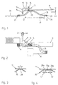
- the thermal tripping device for example in a circuit breaker can be installed, has a connection contact 20, which is stationary in the circuit breaker is housed and belongs, for example, to a connecting terminal.
- a holding part 10 for is fixedly accommodated within the line switch a bimetal 11, which bracket part 10 is L-shaped with a Leg 12 and a further leg 13.
- On the leg 13 is a bimetallic support 15 attached, which is also L-shaped and the leg 13 on both sides includes what is of little importance for the invention.
- the thermobimetal 11 is attached so that the thermobimetal 11th together with the other leg 16 approximately parallel to the leg 12 of the L-shaped Bracket part 10 of the bimetal 11 extends.
- an adjustment screw 14 screwed which bears against the thermal bimetal 11 and with which is the distance from the free end of the bimetal to one of the latching points in a switch lock of the circuit breaker associated lever 45 set becomes.
- a contact lever 25 on which a movable Contact piece 30 is attached, which cooperates with a fixed contact piece.
- the contact lever 25 can be pivoted, for example, about an axis of rotation D.
- a line connection between the fixed connection contact 20 and a starting point 26 on the contact lever 25 is achieved by means of a stranded wire 35, on the one hand at the connection contact 20 via a first welded connection 27, at the bimetal 11 via a weld 28 and at the starting point 26 via a weld 29 with the Contact lever 25 is connected.
- the current thus flows through the welding point 27 from the fixed connection contact 20 in the stranded conductor 35 and continues to flow through the welding point 29, the connection point between the stranded conductor 35 and the Contact lever 25, so that in this arrangement two welds flowed through by the current are.
- the weld connection 28 between the stranded conductor 35 and the bimetal 11 does not flow through the current in this sense;
- the power is on quasi parallel to the bimetal 11 through the stranded conductor 35 fixed there, so that both the bimetal holder 10, the carrier 15 and the thermobimetal 11 itself are without power.
- Fig. 2 shows the fixation of the bimetallic mounting part 10 in a recess 41 of the Housing 40 of the circuit breaker.
- the stranded conductor 35 is over a length L welded to the bimetal 11, the length L being chosen so that a sufficient heat transfer from the stranded conductor 35 to the bimetal 11 is achieved.
- an embodiment according to FIG. 4 can also be used become.
- the stranded conductor 35 is on the thermobimetal 11 via two welding spots 28a and 28b, the direct contact length consisting of two sections with the Part lengths L1 and L2 is composed.
- this will also be between the two fastening points 28a and 28b section 35a of the stranded conductor 35 contribute to the heat transfer and heating of the thermal bimetal 11; the The contribution of the direct contact points 28a and 28b is, however, significantly larger.
- the invention is chosen based on an exemplary representation; there are also Variants of the arrangement, for example, as far as the movable contact piece Can be double contact piece with which two fixed spaced apart Contact piece are bridged.
- the stranded wire 35 can also be fixed to the thermobimetal 11 at more points than shown in FIG. 4.
Landscapes
- Physics & Mathematics (AREA)
- Electromagnetism (AREA)
- Thermally Actuated Switches (AREA)
- Breakers (AREA)
- Protection Of Generators And Motors (AREA)
- Vending Machines For Individual Products (AREA)
- Pharmaceuticals Containing Other Organic And Inorganic Compounds (AREA)
- Medicinal Preparation (AREA)
Abstract
Description
- Fig. 1
- eine Seitenansicht einer thermischen Auslöseeinrichtung,
- Fig. 2
- eine Aufsicht auf die thermische Auslösevorrichtung, und
- Fig. 3 und 4
- zwei Varianten der Befestigungsstelle des Litzenleiters am Thermobimetall.
Claims (4)
- Thermische Auslöseeinrichtung mit einem thermomechanischen Wandler, z. B. einem Thermobimetall, für ein elektriches Schaltgerät mit einem feststehenden und beweglichen kontaktstück und einer Fixierungsstelle für den thermomechanischen Wandler, dadurch gekennzeichnet, daß zwischen einem ortsfesten Anschlußkontakt (20) beispielsweise an einer Anschlußklemme und dem feststehenden oder beweglichen Kontaktstück (30) ein Litzenleiter (35) vorgesehen ist, der einerseits an dem ortsfesten Anschlußkontakt (20), dem feststehenden oder beweglichen Kontaktstück (30) und andererseits an dem thermomechanischen Wandler (11) befestigt ist.
- Thermische Auslöseeinrichtung nach Anspruch 1, dadurch gekennzeichnet, daß der Litzenleiter (35) mittels Schweißverbindungen an dem ortsfesten Anschlußkontakt (20), dem thermomechanischen Wandler (11) und dem feststehenden oder beweglichen Kontaktstück (30) fixiert ist.
- Thermische Auslöseeinrichtung für ein Schaltgerät, dessen bewegliches Kontaktstück an einem beweglichen bzw. schwenkbaren Kontakthebel befestigt ist, dadurch gekennzeichnet, daß der Litzenleiter (35) an dem beweglichen Kontakthebel (25) befestigt ist.
- Thermomechanischer Wandler nach einem der vorherigen Ansprüche, dadurch gekennzeichnet, daß der Litzenleiter (35) mittels wenigstens zweier Schweißpunkte am thermomechanischen Wandler (11) fixiert ist.
Applications Claiming Priority (2)
| Application Number | Priority Date | Filing Date | Title |
|---|---|---|---|
| DE19912124A DE19912124B4 (de) | 1999-03-18 | 1999-03-18 | Thermische Auslöseeinrichtung |
| DE19912124 | 1999-03-18 |
Publications (3)
| Publication Number | Publication Date |
|---|---|
| EP1037242A2 true EP1037242A2 (de) | 2000-09-20 |
| EP1037242A3 EP1037242A3 (de) | 2002-04-10 |
| EP1037242B1 EP1037242B1 (de) | 2009-01-07 |
Family
ID=7901450
Family Applications (1)
| Application Number | Title | Priority Date | Filing Date |
|---|---|---|---|
| EP00104871A Expired - Lifetime EP1037242B1 (de) | 1999-03-18 | 2000-03-07 | Thermische Auslöseeinrichtung |
Country Status (4)
| Country | Link |
|---|---|
| EP (1) | EP1037242B1 (de) |
| AT (1) | ATE420450T1 (de) |
| DE (2) | DE19912124B4 (de) |
| PL (1) | PL339050A1 (de) |
Families Citing this family (1)
| Publication number | Priority date | Publication date | Assignee | Title |
|---|---|---|---|---|
| DE102006016648A1 (de) * | 2006-04-08 | 2007-10-11 | Hella Kgaa Hueck & Co. | Fernbedienbarer Hochstromschalter |
Family Cites Families (8)
| Publication number | Priority date | Publication date | Assignee | Title |
|---|---|---|---|---|
| US2043306A (en) * | 1932-10-29 | 1936-06-09 | Westinghouse Electric & Mfg Co | Circuit interrupter |
| US2884501A (en) * | 1956-05-31 | 1959-04-28 | Tung Sol Electric Inc | Circuit protective device |
| ZA698654B (en) * | 1969-12-12 | 1971-05-27 | Fuchs Electrical Ind Ltd | Improvements in or relating to overload protection for electric motors |
| DE7828060U1 (de) * | 1978-09-21 | 1979-11-29 | Licentia Patent-Verwaltungs-Gmbh, 6000 Frankfurt | Bimetallauslöser |
| DE3734396A1 (de) * | 1987-10-10 | 1989-04-27 | Asea Brown Boveri | Elektrisches schaltgeraet |
| FR2722331B1 (fr) * | 1994-07-08 | 1996-09-27 | Legrand Sa | Sous-ensemble thermique pour disjoncteur |
| DE4445170C2 (de) * | 1994-12-17 | 1997-02-13 | Abb Patent Gmbh | Thermischer Auslöser |
| DE19838417B4 (de) * | 1998-08-24 | 2004-04-29 | Aeg Niederspannungstechnik Gmbh & Co Kg | Thermische Auslösevorrichtung |
-
1999
- 1999-03-18 DE DE19912124A patent/DE19912124B4/de not_active Expired - Fee Related
-
2000
- 2000-03-07 DE DE50015508T patent/DE50015508D1/de not_active Expired - Lifetime
- 2000-03-07 EP EP00104871A patent/EP1037242B1/de not_active Expired - Lifetime
- 2000-03-07 AT AT00104871T patent/ATE420450T1/de not_active IP Right Cessation
- 2000-03-16 PL PL00339050A patent/PL339050A1/xx not_active Application Discontinuation
Also Published As
| Publication number | Publication date |
|---|---|
| DE19912124B4 (de) | 2007-10-11 |
| EP1037242B1 (de) | 2009-01-07 |
| EP1037242A3 (de) | 2002-04-10 |
| PL339050A1 (en) | 2000-09-25 |
| ATE420450T1 (de) | 2009-01-15 |
| DE50015508D1 (de) | 2009-02-26 |
| DE19912124A1 (de) | 2000-09-21 |
Similar Documents
| Publication | Publication Date | Title |
|---|---|---|
| DE3615707C2 (de) | ||
| DE9214940U1 (de) | Temperaturwächter | |
| DE10152347C1 (de) | Schaltgerät mit adaptiertem mehrphasigem Sammelschienensystem | |
| DE4406670C2 (de) | Leitungsschutzschalter | |
| DE10209905A1 (de) | Elektrisches Heizgerät, insbesondere Durchlauferhitzer | |
| DE29918974U1 (de) | Elektrisches Schutzschaltgerät | |
| EP1037242B1 (de) | Thermische Auslöseeinrichtung | |
| DE3709875C2 (de) | ||
| DE2927879A1 (de) | Kontaktanordnung fuer leitungsschutzschalter | |
| DE3338799A1 (de) | Thermischer ausloeser | |
| EP1728311A1 (de) | Vorrichtung zum verbinden des mantels einer elektrischen wicklung mit einer erdungsleitung und damit ausgerüstete magnetschwebebahn | |
| DE19818704C1 (de) | Montagefuß mit Schutzleiterfunktion für elektr. Klemmen | |
| DE2737618A1 (de) | Anschluss des stromwandlers eines mit leitungsschutzschaltern kombinierten fehlerstromausloesers | |
| EP0660444B1 (de) | Niederspannungsverteiler | |
| DE3740339C2 (de) | Schalter und Verfahren zur Herstellung eines Schalters | |
| DE19952179A1 (de) | Elektrisches Schutzschaltgerät | |
| DE69818630T2 (de) | Bewegbares Kontaktelement für Hochspannungsleistungsschalter, und expandierbar | |
| EP4221476B1 (de) | Stromleitungsrohr und stromrichteranordnung mit einem solchen | |
| DE1916079B2 (de) | Sammelschienenabzweig für Mittelspannungsschal tzelle | |
| DE29604726U1 (de) | Stromzuführung für armförmige bewegliche Kontakte eines Niederspannungs-Schutzschalters | |
| AT394791B (de) | Kurzschlussfeste stromschienenverbindung mit einem flexiblen dehnungsband | |
| DE102008048837A1 (de) | Konstruktionsanordnung eines Sanftanlaufgeräts | |
| DE1538407A1 (de) | Thermischer UEberlastschalter,insbesondere fuer Motorschutzschalter | |
| DE1268249B (de) | Schaltanlagen-Reihenklemme fuer Schutzleiter | |
| EP0185277B2 (de) | Elektrischer Leitungsschutzschalter |
Legal Events
| Date | Code | Title | Description |
|---|---|---|---|
| PUAI | Public reference made under article 153(3) epc to a published international application that has entered the european phase |
Free format text: ORIGINAL CODE: 0009012 |
|
| AK | Designated contracting states |
Kind code of ref document: A2 Designated state(s): AT BE CH CY DE DK ES FI FR GB GR IE IT LI LU MC NL PT SE |
|
| AX | Request for extension of the european patent |
Free format text: AL;LT;LV;MK;RO;SI PAYMENT 20000315 |
|
| RAP1 | Party data changed (applicant data changed or rights of an application transferred) |
Owner name: ABB PATENT GMBH |
|
| PUAL | Search report despatched |
Free format text: ORIGINAL CODE: 0009013 |
|
| AK | Designated contracting states |
Kind code of ref document: A3 Designated state(s): AT BE CH CY DE DK ES FI FR GB GR IE IT LI LU MC NL PT SE |
|
| AX | Request for extension of the european patent |
Free format text: AL;LT;LV;MK;RO;SI PAYMENT 20000315 |
|
| RIC1 | Information provided on ipc code assigned before grant |
Free format text: 7H 01H 71/16 A, 7H 01H 1/58 B |
|
| 17P | Request for examination filed |
Effective date: 20020413 |
|
| AKX | Designation fees paid |
Free format text: AT BE CH CY DE DK ES FI FR GB GR IE IT LI LU MC NL PT SE |
|
| AXX | Extension fees paid |
Free format text: SI PAYMENT 20000315 |
|
| 17Q | First examination report despatched |
Effective date: 20061201 |
|
| RAP1 | Party data changed (applicant data changed or rights of an application transferred) |
Owner name: ABB AG |
|
| GRAP | Despatch of communication of intention to grant a patent |
Free format text: ORIGINAL CODE: EPIDOSNIGR1 |
|
| GRAS | Grant fee paid |
Free format text: ORIGINAL CODE: EPIDOSNIGR3 |
|
| GRAA | (expected) grant |
Free format text: ORIGINAL CODE: 0009210 |
|
| AK | Designated contracting states |
Kind code of ref document: B1 Designated state(s): AT BE CH CY DE DK ES FI FR GB GR IE IT LI LU MC NL PT SE |
|
| AX | Request for extension of the european patent |
Extension state: SI |
|
| REG | Reference to a national code |
Ref country code: GB Ref legal event code: FG4D Free format text: NOT ENGLISH |
|
| REG | Reference to a national code |
Ref country code: CH Ref legal event code: EP |
|
| REG | Reference to a national code |
Ref country code: IE Ref legal event code: FG4D Free format text: LANGUAGE OF EP DOCUMENT: GERMAN |
|
| REF | Corresponds to: |
Ref document number: 50015508 Country of ref document: DE Date of ref document: 20090226 Kind code of ref document: P |
|
| PG25 | Lapsed in a contracting state [announced via postgrant information from national office to epo] |
Ref country code: NL Free format text: LAPSE BECAUSE OF FAILURE TO SUBMIT A TRANSLATION OF THE DESCRIPTION OR TO PAY THE FEE WITHIN THE PRESCRIBED TIME-LIMIT Effective date: 20090107 |
|
| NLV1 | Nl: lapsed or annulled due to failure to fulfill the requirements of art. 29p and 29m of the patents act | ||
| PG25 | Lapsed in a contracting state [announced via postgrant information from national office to epo] |
Ref country code: FI Free format text: LAPSE BECAUSE OF FAILURE TO SUBMIT A TRANSLATION OF THE DESCRIPTION OR TO PAY THE FEE WITHIN THE PRESCRIBED TIME-LIMIT Effective date: 20090107 Ref country code: ES Free format text: LAPSE BECAUSE OF FAILURE TO SUBMIT A TRANSLATION OF THE DESCRIPTION OR TO PAY THE FEE WITHIN THE PRESCRIBED TIME-LIMIT Effective date: 20090418 |
|
| REG | Reference to a national code |
Ref country code: IE Ref legal event code: FD4D |
|
| PG25 | Lapsed in a contracting state [announced via postgrant information from national office to epo] |
Ref country code: PT Free format text: LAPSE BECAUSE OF FAILURE TO SUBMIT A TRANSLATION OF THE DESCRIPTION OR TO PAY THE FEE WITHIN THE PRESCRIBED TIME-LIMIT Effective date: 20090608 Ref country code: SE Free format text: LAPSE BECAUSE OF FAILURE TO SUBMIT A TRANSLATION OF THE DESCRIPTION OR TO PAY THE FEE WITHIN THE PRESCRIBED TIME-LIMIT Effective date: 20090407 |
|
| BERE | Be: lapsed |
Owner name: ABB A.G. Effective date: 20090331 |
|
| PG25 | Lapsed in a contracting state [announced via postgrant information from national office to epo] |
Ref country code: MC Free format text: LAPSE BECAUSE OF NON-PAYMENT OF DUE FEES Effective date: 20090331 Ref country code: IE Free format text: LAPSE BECAUSE OF FAILURE TO SUBMIT A TRANSLATION OF THE DESCRIPTION OR TO PAY THE FEE WITHIN THE PRESCRIBED TIME-LIMIT Effective date: 20090107 Ref country code: DK Free format text: LAPSE BECAUSE OF FAILURE TO SUBMIT A TRANSLATION OF THE DESCRIPTION OR TO PAY THE FEE WITHIN THE PRESCRIBED TIME-LIMIT Effective date: 20090107 |
|
| REG | Reference to a national code |
Ref country code: CH Ref legal event code: PL |
|
| PLBE | No opposition filed within time limit |
Free format text: ORIGINAL CODE: 0009261 |
|
| STAA | Information on the status of an ep patent application or granted ep patent |
Free format text: STATUS: NO OPPOSITION FILED WITHIN TIME LIMIT |
|
| 26N | No opposition filed |
Effective date: 20091008 |
|
| GBPC | Gb: european patent ceased through non-payment of renewal fee |
Effective date: 20090407 |
|
| PG25 | Lapsed in a contracting state [announced via postgrant information from national office to epo] |
Ref country code: LI Free format text: LAPSE BECAUSE OF NON-PAYMENT OF DUE FEES Effective date: 20090331 Ref country code: CH Free format text: LAPSE BECAUSE OF NON-PAYMENT OF DUE FEES Effective date: 20090331 |
|
| PG25 | Lapsed in a contracting state [announced via postgrant information from national office to epo] |
Ref country code: BE Free format text: LAPSE BECAUSE OF NON-PAYMENT OF DUE FEES Effective date: 20090331 |
|
| PG25 | Lapsed in a contracting state [announced via postgrant information from national office to epo] |
Ref country code: GB Free format text: LAPSE BECAUSE OF NON-PAYMENT OF DUE FEES Effective date: 20090407 |
|
| PG25 | Lapsed in a contracting state [announced via postgrant information from national office to epo] |
Ref country code: AT Free format text: LAPSE BECAUSE OF NON-PAYMENT OF DUE FEES Effective date: 20090307 |
|
| PG25 | Lapsed in a contracting state [announced via postgrant information from national office to epo] |
Ref country code: GR Free format text: LAPSE BECAUSE OF FAILURE TO SUBMIT A TRANSLATION OF THE DESCRIPTION OR TO PAY THE FEE WITHIN THE PRESCRIBED TIME-LIMIT Effective date: 20090408 |
|
| PG25 | Lapsed in a contracting state [announced via postgrant information from national office to epo] |
Ref country code: IT Free format text: LAPSE BECAUSE OF FAILURE TO SUBMIT A TRANSLATION OF THE DESCRIPTION OR TO PAY THE FEE WITHIN THE PRESCRIBED TIME-LIMIT Effective date: 20090107 |
|
| PG25 | Lapsed in a contracting state [announced via postgrant information from national office to epo] |
Ref country code: LU Free format text: LAPSE BECAUSE OF NON-PAYMENT OF DUE FEES Effective date: 20090307 |
|
| PG25 | Lapsed in a contracting state [announced via postgrant information from national office to epo] |
Ref country code: CY Free format text: LAPSE BECAUSE OF FAILURE TO SUBMIT A TRANSLATION OF THE DESCRIPTION OR TO PAY THE FEE WITHIN THE PRESCRIBED TIME-LIMIT Effective date: 20090107 |
|
| REG | Reference to a national code |
Ref country code: FR Ref legal event code: PLFP Year of fee payment: 17 |
|
| PGFP | Annual fee paid to national office [announced via postgrant information from national office to epo] |
Ref country code: FR Payment date: 20160321 Year of fee payment: 17 |
|
| REG | Reference to a national code |
Ref country code: FR Ref legal event code: ST Effective date: 20171130 |
|
| PG25 | Lapsed in a contracting state [announced via postgrant information from national office to epo] |
Ref country code: FR Free format text: LAPSE BECAUSE OF NON-PAYMENT OF DUE FEES Effective date: 20170331 |
|
| PGFP | Annual fee paid to national office [announced via postgrant information from national office to epo] |
Ref country code: DE Payment date: 20190321 Year of fee payment: 20 |
|
| REG | Reference to a national code |
Ref country code: DE Ref legal event code: R071 Ref document number: 50015508 Country of ref document: DE |