EP1035455A1 - Système de supervision arrière - Google Patents
Système de supervision arrière Download PDFInfo
- Publication number
- EP1035455A1 EP1035455A1 EP00105113A EP00105113A EP1035455A1 EP 1035455 A1 EP1035455 A1 EP 1035455A1 EP 00105113 A EP00105113 A EP 00105113A EP 00105113 A EP00105113 A EP 00105113A EP 1035455 A1 EP1035455 A1 EP 1035455A1
- Authority
- EP
- European Patent Office
- Prior art keywords
- vehicle
- road
- white
- image
- lane
- Prior art date
- Legal status (The legal status is an assumption and is not a legal conclusion. Google has not performed a legal analysis and makes no representation as to the accuracy of the status listed.)
- Withdrawn
Links
- 238000012544 monitoring process Methods 0.000 title claims abstract description 50
- 230000003287 optical effect Effects 0.000 claims description 20
- 238000001514 detection method Methods 0.000 claims description 15
- 241000380131 Ammophila arenaria Species 0.000 claims description 12
- 238000012806 monitoring device Methods 0.000 claims description 11
- 238000012545 processing Methods 0.000 description 61
- 238000010586 diagram Methods 0.000 description 4
- 238000000034 method Methods 0.000 description 3
- 238000013459 approach Methods 0.000 description 2
- 230000004313 glare Effects 0.000 description 2
- 238000004519 manufacturing process Methods 0.000 description 2
- 239000011159 matrix material Substances 0.000 description 2
- 239000013598 vector Substances 0.000 description 2
- 230000003044 adaptive effect Effects 0.000 description 1
- 230000004075 alteration Effects 0.000 description 1
- 238000007796 conventional method Methods 0.000 description 1
- 230000008878 coupling Effects 0.000 description 1
- 238000010168 coupling process Methods 0.000 description 1
- 238000005859 coupling reaction Methods 0.000 description 1
- 230000005236 sound signal Effects 0.000 description 1
Images


Classifications
-
- G—PHYSICS
- G05—CONTROLLING; REGULATING
- G05D—SYSTEMS FOR CONTROLLING OR REGULATING NON-ELECTRIC VARIABLES
- G05D1/00—Control of position, course, altitude or attitude of land, water, air or space vehicles, e.g. using automatic pilots
- G05D1/02—Control of position or course in two dimensions
- G05D1/021—Control of position or course in two dimensions specially adapted to land vehicles
- G05D1/0231—Control of position or course in two dimensions specially adapted to land vehicles using optical position detecting means
- G05D1/0246—Control of position or course in two dimensions specially adapted to land vehicles using optical position detecting means using a video camera in combination with image processing means
- G05D1/0253—Control of position or course in two dimensions specially adapted to land vehicles using optical position detecting means using a video camera in combination with image processing means extracting relative motion information from a plurality of images taken successively, e.g. visual odometry, optical flow
-
- G—PHYSICS
- G05—CONTROLLING; REGULATING
- G05D—SYSTEMS FOR CONTROLLING OR REGULATING NON-ELECTRIC VARIABLES
- G05D1/00—Control of position, course, altitude or attitude of land, water, air or space vehicles, e.g. using automatic pilots
- G05D1/02—Control of position or course in two dimensions
- G05D1/021—Control of position or course in two dimensions specially adapted to land vehicles
- G05D1/0276—Control of position or course in two dimensions specially adapted to land vehicles using signals provided by a source external to the vehicle
- G05D1/0278—Control of position or course in two dimensions specially adapted to land vehicles using signals provided by a source external to the vehicle using satellite positioning signals, e.g. GPS
Definitions
- the present invention relates to a rear (inclusive of rear-side or diagonal rear) monitoring system, and more particularly to a rear monitoring system for picking up the road image on the rear of one's own vehicle by an image pick-up means such as a video camera installed on the vehicle such as a motor car, detecting another vehicle approaching from the diagonal-rear direction of one's own running vehicle using the road image picked up and giving a warning to a driver.
- an image pick-up means such as a video camera installed on the vehicle such as a motor car
- Figs. 11A - 11C are views for explaining a change in a rear background image acquired by a video camera 1.
- Fig. 11A shows a status inclusive of one's own vehicle.
- Fig. 11B shows an image picked up by a video camera 1 at timing t in an environment of one's own vehicle.
- Fig. 11C shows an image picked up at timing t + ⁇ t.
- a technique of searching corresponding points using two cameras is adopted. Specifically, an edge point Pa of an object is detected from a luminance difference between the adjacent pixels on the image picked up by a camera. A point Pb of the image picked up by another camera corresponding to the detected edge point is detected. The position of another approaching vehicle is acquired by the pixel coordinates of Pa and Pb. On the basis of the position acquired, the pertinent driver is given a warning of the existence of another vehicle approaching his own vehicle.
- a conventional technique of detecting the location of a detected other vehicle in such a manner that the road image on a straight speed way having one-side three lanes as shown in Fig. 12 is image-processed to detect the white lines (each of which is a lane-dividing line such as a white line, yellow line, white broken line, etc., and hereinafter referred to as "white line") of the lane on which one's own vehicle is running so that one's own lane is discriminated from the adjacent lane and any other vehicle is detected for each monitoring lane so that it is decided whether the detected vehicle is located on the one's own lane or the other adjacent lane.
- the monitoring area is defined in order to save the processing time for the lane which is not required for monitoring.
- the prior art detects white lines by a technique of image processing.
- the glare of light may obstruct the safe running of the following vehicle so that it is dangerous to project light to a far distance.
- An object of the present invention is to provide a rear monitoring system for a vehicle which can easily detect white lines for discriminating one's own lane from an adjacent lane.
- a diagonal-rear monitoring system for a vehicle for monitoring a relationship between one's own vehicle and another vehicle comprising:
- the white lines on the diagonal-rear road image can be estimated using the information on the road on which one's own vehicle has run.
- the information acquisition means comprises:
- the white lines can be estimated.
- the diagonal-from image pick-up means and the white-line information acquisition means are those originally installed in the system.
- the information acquisition means comprises position information acquisition means 31b-1 for acquiring vehicle position information indicative of a position coordinate of a vehicle at a prescribed period when the vehicle is running on one's own lane, the position information varying according to a helm angle and running speed of the vehicle, and
- the white lines can be easily estimated by only acquiring the vehicle position information on the basis of the helm angle and running speed.
- a diagonal-rear monitoring system for a vehicle for monitoring a relationship between one's own vehicle and another vehicle comprising:
- the white lines on the diagonal-rear road image can be easily estimated using the road information.
- the map storage means and the information acquisition means are those of a GPS navigation device originally installed to inform a driver of a present location of one's own vehicle on a map on a display.
- a diagonal-rear monitoring system for a vehicle for monitoring a relationship between one's own vehicle and another following vehicle using an optical flow comprising:
- a diagonal-rear monitoring system for a vehicle for monitoring a relationship between one's own vehicle and another following vehicle using an optical flow comprising:
- the white lines can be estimated on the basis of the road information, the white lines on the diagonal-rear road image can be easily estimated through acquisition of the road image.
- a diagonal-rear monitoring system for a vehicle for monitoring a relationship between one's own vehicle and another vehicle comprising:
- the retrieval region is set using white-line information acquired on the basis of a front image pick-up in a front monitoring device originally.
- the white lines can be detected through the retrieval of only the retrieval region set by the the retrieval region setting means 31e.
- Fig. 2 shows an embodiment of a rear monitoring system for a vehicle according to the present invention.
- reference numeral 10 denotes an image pick-up section serving as an image pick-up means.
- Reference numeral 20 denotes a storage section for storing image data and others.
- Reference numeral 30 denotes a data processing section A for implementing image processing and monitoring a relationship with other vehicles on the basis of the image information from the image pick-up section 10.
- Reference numeral 40 denotes a warning section for giving a warning.
- Reference numeral 50 denotes a signal input section for receiving a signal indicative of the operation information when the running direction of one's own vehicle is changed.
- the image pick-up section 10 which may be a video camera, includes a lens 11a and image plane 11b.
- the video camera A11 is attached to the upper or rear side of the trunk portion on the rear side of a vehicle so that it is oriented rearward.
- the video camera A11 is configured to pick up the image of the road on the rear of one's own vehicle.
- the video camera A11 supplies the data D1 of the image thus acquired to a data processing section A30.
- the storage section 20 includes a first and a second frame memory 21 and 22, a front white-line frame memory 21 and a divergent optical flow memory 24.
- the first and the second frame memory 21 and 22 temporarily store, as pixel data D2 and D3, the pixels in a m- by n- matrix (e.g. 512 x 512 pixels and with the luminance in 0 - 255 tones) converted from the diagonal-rear road image data D1 imaged on the image plane 11b of the video camera A11, and supplies them to the data processing section A30.
- n- matrix e.g. 512 x 512 pixels and with the luminance in 0 - 255 tones
- first and the second frame memory 21 successively store the m x n pixel data D2 and D3 converted from the diagonal-rear road image picked up at an established period ⁇ t in such a manner that it is stored in the first frame memory 21 at timing t, in the second frame memory 22 at timing t + ⁇ t , ... ... .
- the diagonal rear white-line frame memory 23 is composed of a first and a second diagonal-rear frame memory (not shown).
- the diagonal rear white-line frame memory 23 temporarily stores the white-line data D4 of the front road image for discriminating one's own lane from the adjacent lane at a predetermined period ⁇ t and supplies it to the data processing section A30.
- the white-line data D4 are acquired from the video camera B61 attached to the front of one's own vehicle and installed in a front monitoring device 60.
- the front monitoring device serves as a collision preventing device.
- the front monitoring device includes a video camera B61 serving as the front image pick-up means, a data processing unit B62 for processing the data supplied from the video camera and a speaker 63 for giving a warning.
- the data processing unit B62 detects the white line to discriminate the one's own lane from the adjacent lane in the front road image picked up by the video camera B61, and decides the danger degree of rear-end collision of the one's own vehicle with another diagonal-front vehicle which is running on the one's own lane.
- the speaker B63 gives a warning.
- the above white-line data D4 is taken from the data processing section B62.
- the front monitoring device was used as the collision preventing device 60.
- it may be used for an adaptive cruise control (ACC).
- the ACC is performed in such a way that the one's own vehicle can follow another vehicle, which runs ahead of the one's own vehicle at a lower speed than a prescribed speed, while it runs at maintaining the distance between both vehicles.
- a vehicle running at the low speed can be detected by detecting the white line to discriminate the one's own lane from the adjacent lane on the front (inclusive of front-side or diagonal front) image picked up by the video camera B61 and the vehicle running on only the one's own lane on the basis of the thus detected white line.
- the video camera B61 installed in the front monitoring device can be used for the above purpose without providing any other separate video camera, the production cost can be reduced.
- the data processing A30 includes a CPU 31 operating along a control program, a ROM 32 for storing the control program for the CPU 31 and an RAM for temporarily storing the data required for the operation by the CPU 31.
- the warning section 40 includes a display 41 and a speaker 42.
- the display 41 which may be an LCD displays the diagonal-rear road image picked up by the video camera A11, or displays a message when it is decided by the data processing unit A that there is danger of contact with another vehicle, thereby visually informing the driver of the danger.
- the speaker 42 produces sound such as an audio guidance or an audible alert. Then it is decided by the data processing section A30 that there is danger of collision or contact with another vehicle, the danger is informed the driver by sound.
- the signal input section 50 includes a light-on detecting switch 51, a winker (turn signal) detecting switch 52 and a running sensor 53.
- the light-on detecting switch 51 serves to detect the "on" of a head light by a driver.
- the winker detecting switch 52 serves to detect the operation state and its operation direction of a winker mechanism by the driver, i.e. turn-around instruction information from a winker mechanism operated when the driver turns the vehicle around toward the right or left side.
- the running sensor 53 serves to detect the running distance of a vehicle.
- step SP110 the processing of acquisition of white-line information is performed by the CPU 31.
- the white-line data D4 of the front road image detected by the data processing section B62 is acquired to estimate the white line of a diagonal-rear road image.
- the white-line data of the front road image thus acquired is stored in the diagonal-front white-line frame memory 23.
- step SP120 the processing of acquiring the diagonal-rear image is performed.
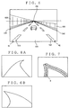
- the rear road image as shown in Fig. 4 is acquired.
- This rear road image is an image viewed from one's own vehicle which is running on a vehicle-dedicated road such as a speed way. Namely, it is the image directly picked up by the video camera A11 attached to the rear of the vehicle so that it is oriented rearward.
- the image includes a road 500, inner white lines 510, 520 and outer white lines 530, 540, and side walls 600.
- the inner white lines 510, 520 are broken lines which are drawn on the road to discriminate one's own vehicle from adjacent lanes, and permit a lane change to be made.
- the outer white lines 530, 540 are continuous solid lines which are drawn on the road to define side roads and prohibit the lane change.
- the image of side walls 600 formed upright on both sides of the road 500 disappears at the center position in a horizontal direction and a position of 1/3 from above in a vertical direction. The disappearing point is referred to as "FOE".
- the data D1 of the rear-diagonal road image thus acquired are converted into the pixel data D2 which is an image in a matrix with m-rows and n-columns.
- the image data D1 are stored in the first frame memory 21 of the storage section 20.
- the FOE line L indicative of the position of the FOE in the vertical direction depends on the view angle of the video camera A11 attached to the rear side of one's own vehicle so as to be oriented rearward, lens aberration, installing parameters (height and elevation angle), etc. For example, it is located at a rear position of 100 meter. The explanation will be made assuming that the FOE line L is located at the rear position of 100 meter.
- step SP130 the output from the light-on detecting switch 51 is read to decide whether or not the head light is "ON" or not. If YES, it is decided that even if the rear road image is processed, the white line cannot be recognized because it is now in the nighttime. The processing proceeds to step SP140 in which white-line estimation is performed by the CPU 31.
- the white-line data D4 100 meter ahead of the position of one's own vehicle at the timing which is a position of the FOE line L, is acquired from the diagonal-front white-line memory 23. For example, if the position of about 100 meter ahead corresponds to the timing t - 2 ⁇ t, two frames ago, as a result of the detection result of the running sensor 53, the white line data D4 at the timing t - 2 ⁇ t is acquired. On the basis of the white-line data D4 at timing t - 2 ⁇ t, the white lines will be estimated as shown in Fig. 5C.
- the estimation of the white lines will be made as follows. For example, it is assumed that in the white line data D4 of the front road picked up 100 meter ahead of one's own vehicle, as shown in Fig. 6A, the line at a relatively near position is straight whereas that at a far position is curved. In this case, in the estimated rear road image, as shown in Fig. 6B, the line at the relatively near position is curved, whereas that at the far position is straight. It can be also estimated that the orientation of the curve of the estimated rear road image is reverse to that of the front road image.
- the white lines can be easily detected in the nighttime when the white lines cannot be detected from the rear road image.
- the white data D4 detected by the front monitoring device 60 is used for estimation, the white lines can be easily detected with no image processing. After the white lines are estimated, the processing proceeds to step SP150.
- step SP130 if "NO” (the headlight is "off"), it is decided that the white lines can be detected from the rear road image since it is now in the daytime, and hence the processing proceeds to step SP160.
- step SP160 the processing of setting a retrieval area is performed by the CPU 31. Referring to Fig. 7, the processing of setting a retrieval area will be explained below.
- a white line H of the rear road image is estimated.
- an area having a prescribed width and shaded as seen from Fig. 7C is set as a retrieval area.
- the processing of detecting a white line is performed by the CPU 31.
- the white line is detected for only the retrieval area. Therefore, the quantity of the image processing for detection of the white line is reduced so that the white line can be easily detected in the daytime. Thereafter, the processing proceeds to step SP150 in Fig. 3.
- step SP150 the processing of setting a monitoring region is performed.
- a monitoring region for one's own lane is set inside region encircled by the white line estimated or detected in step SP140 or 170, whereas that for the adjacent lane is set in the region outside the white line and particularly encircled by the FOE line L.
- the processing proceeds to step SP180.
- step SP180 the processing of detecting an optical flow is performed by the CPU 31.
- the processing of detecting the optical flow is performed for each of the monitoring regions set in step SP150.
- the monitoring region is set in both adjacent lanes on both sides of one's own lane, it is picked up later than the road image stored in the first frame memory 21 by a prescribed time ⁇ t.
- the same monitoring region is set for the road image stored in the second frame memory 22.
- the moving direction and moving distance between each of the points constituting the road image at timing t and the corresponding points at timing t + ⁇ t can be detected as the optical flow.
- step SP190 the processing of computing the degree of danger will be made.
- the magnitude (or length) of the optical flow in a diverging direction from the FOE is weighted so that it takes a numerical form.
- the level of danger may be computed.
- step SP200 on the basis of the degree of danger thus computed, if it exceeds the threshold value, decision of being danger is made. Otherwise, if the level of danger exceeds a prescribed value, decision of being dangerous is made.
- step SP210 the processing of warning is executed. If the decision of being not dangerous, the processing is ended. Subsequently, the processing from step SP110 will be started again.
- step SP210 an audio signal is sent to the speaker 42 in the warning section 40.
- An audio guidance or audible alert is produced so that the attention of the driver is attracted.
- a message is displayed on the display 41 so that the danger is visually informed the driver.
- the information on the road on which one's own vehicle has run is acquired by acquiring the white line data D4 on the front road image (position information acquiring means 61).
- position information acquiring means 61 it may be acquired from the position coordinate which can be computed on the basis of the helm angle (obtained by a helm angel sensor) and running speed obtained by the running sensor 53 (position coordinate acquiring means 31b-1).
- the white line positions W1 and W2 move in accordance with the helm angle. Therefore, they may be detected by the image processing for an minimum image processing region which is defined on the outer periphery of the rear road image corresponding to the range of the white line moving according to the helm angle. The image processing is made while attention is paid to the fact that luminance is stronger at the two positions intersecting the outer edge of the rear road image than the other positions. Further, if the white line positions W1 and W2 according to the helm angle, which can be sensed by the helm angle sensor attached to the rear monitoring device, are previously stored, the white line positions W1 and W2 according to the helm angle.
- the white lines on the rear road image can be easily estimated without making the image processing by acquisition of the helm angle and running speed regardless of the daytime and nighttime. Even if the white lines cannot be detected from the front road image, they can be estimated.
- Fig. 10 is a block diagram of the second embodiment of the rear monitoring device.
- like reference numerals refer to like elements in the first embodiment shown in Fig. 2.
- a data processing A30 receives present position data D7 from a GPS receiver 72 which is an information acquiring means through a GPS antenna 71 and map data D8 from a map database 74 which is map storage means.
- the GPS antenna 71, GPS receiver 72 and map data base 74 are included in a GPS navigation apparatus 70 in which the map data D8 corresponding to the present position data D7 are read out from the map data base 74 stored in a large-capacity memory such as a CD-ROM by the data processing section C73 and displayed on the display 41.
- Use of the GPS navigation apparatus intends to reduce the production cost.
- step SP110 is not performed, and the subsequent SP120 - SP130 are performed in the same manner as in the first embodiment.
- step SP130 if the light is "ON", it is decided that the white line cannot be detected from the rear road image, and the processing of white line estimation in step SP140 is performed. Referring to Fig. 9, an example of the white line estimation in step SP140 will be explained.
- the present position data D7 received by the GPS receiver are read out.
- the map data D8 corresponding to the present position data D7 are read out from the map data base 64.
- the image of a road shape 100-meter behind from the present position is acquired on the basis of the read present position data D7 and map data D8. Assuming that road shape R2 as shown in Fig. 8 has been plotted, two white line positions W1 and W2 intersecting the outer edge of the rear road image are connected to the point P which is located at 100 meter behind along the locus as two curves. These curves are estimated as white lines.
- step 130 if the light is "OFF", it is decided that the white lines can be detected from the rear image. Subsequently, in the processing of detection of the white lines in step SP 160, the white lines constituting both ends of the lane on which one's own vehicle runs are detected from the rear-diagonal road map acquired by the video camera A11. Thereafter, the processing in each of steps SP150 - SP210 will be executed.
Landscapes
- Engineering & Computer Science (AREA)
- Physics & Mathematics (AREA)
- Radar, Positioning & Navigation (AREA)
- Multimedia (AREA)
- Electromagnetism (AREA)
- Aviation & Aerospace Engineering (AREA)
- Computer Vision & Pattern Recognition (AREA)
- Remote Sensing (AREA)
- General Physics & Mathematics (AREA)
- Automation & Control Theory (AREA)
- Traffic Control Systems (AREA)
- Closed-Circuit Television Systems (AREA)
- Navigation (AREA)
- Emergency Alarm Devices (AREA)
- Studio Devices (AREA)
Applications Claiming Priority (2)
| Application Number | Priority Date | Filing Date | Title |
|---|---|---|---|
| JP11066040A JP2000259998A (ja) | 1999-03-12 | 1999-03-12 | 車両用後側方監視装置 |
| JP6604099 | 1999-03-12 |
Publications (1)
| Publication Number | Publication Date |
|---|---|
| EP1035455A1 true EP1035455A1 (fr) | 2000-09-13 |
Family
ID=13304381
Family Applications (1)
| Application Number | Title | Priority Date | Filing Date |
|---|---|---|---|
| EP00105113A Withdrawn EP1035455A1 (fr) | 1999-03-12 | 2000-03-10 | Système de supervision arrière |
Country Status (3)
| Country | Link |
|---|---|
| US (1) | US6360170B1 (fr) |
| EP (1) | EP1035455A1 (fr) |
| JP (1) | JP2000259998A (fr) |
Cited By (7)
| Publication number | Priority date | Publication date | Assignee | Title |
|---|---|---|---|---|
| US6424273B1 (en) | 2001-03-30 | 2002-07-23 | Koninklijke Philips Electronics N.V. | System to aid a driver to determine whether to change lanes |
| WO2003005102A1 (fr) * | 2001-06-30 | 2003-01-16 | Robert Bosch Gmbh | Systeme de visualisation tete haute et procede de representation correctement localisee d'un objet dans l'espace exterieur d'un vehicule par rapport a la position du conducteur |
| EP1281983A3 (fr) * | 2001-08-03 | 2004-01-02 | Nissan Motor Co., Ltd. | Dispositif pour la reconnaissance de l'environnement |
| WO2005036498A1 (fr) * | 2003-09-16 | 2005-04-21 | Robert Bosch Gmbh | Procede et dispositif d'emission d'une alerte |
| FR2861487A1 (fr) * | 2003-10-24 | 2005-04-29 | Renault Sa | Procede de detection d'une sortie de voie de circulation |
| WO2007033870A1 (fr) * | 2005-09-21 | 2007-03-29 | Robert Bosch Gmbh | Procede et systeme d'aide a la conduite pour la commande de demarrage d'un vehicule automobile basee sur un capteur |
| CN105894806A (zh) * | 2016-06-28 | 2016-08-24 | 国网山东省电力公司济南供电公司 | 社会车辆占用变电站工程专用车道的驱赶系统及工作过程 |
Families Citing this family (28)
| Publication number | Priority date | Publication date | Assignee | Title |
|---|---|---|---|---|
| JP3872638B2 (ja) * | 2000-08-29 | 2007-01-24 | 株式会社日立製作所 | クルーズコントロールシステムおよびそれが搭載された車両 |
| KR20020053115A (ko) * | 2000-12-26 | 2002-07-05 | 이계안 | 단일 필드를 이용한 영상 처리방법 |
| US6552656B2 (en) * | 2001-04-12 | 2003-04-22 | Horizon Navigation, Inc. | Method and apparatus for generating notification of changed conditions behind a vehicle |
| US6882287B2 (en) * | 2001-07-31 | 2005-04-19 | Donnelly Corporation | Automotive lane change aid |
| DE10138719A1 (de) * | 2001-08-07 | 2003-03-06 | Siemens Ag | Verfahren und Vorrichtung zur Darstellung von Fahrhinweisen, insbesondere in Auto-Navigationssystemen |
| US6542085B1 (en) * | 2001-10-04 | 2003-04-01 | Whetron Industrial Co., Ltd. | Distance measuring and monitoring device equipped automobile reverse radar |
| JP4016735B2 (ja) * | 2001-11-30 | 2007-12-05 | 株式会社日立製作所 | レーンマーク認識方法 |
| JP3661684B2 (ja) | 2002-11-28 | 2005-06-15 | 日産自動車株式会社 | 車線逸脱防止装置 |
| JP3922173B2 (ja) * | 2002-12-18 | 2007-05-30 | トヨタ自動車株式会社 | 運転補助システム及び装置 |
| JP3791490B2 (ja) | 2002-12-18 | 2006-06-28 | トヨタ自動車株式会社 | 運転補助システム及び装置 |
| US6930593B2 (en) * | 2003-02-24 | 2005-08-16 | Iteris, Inc. | Lane tracking system employing redundant image sensing devices |
| US7197388B2 (en) * | 2003-11-06 | 2007-03-27 | Ford Global Technologies, Llc | Roll stability control system for an automotive vehicle using an external environmental sensing system |
| JP2005170323A (ja) * | 2003-12-15 | 2005-06-30 | Denso Corp | 走路形状表示装置 |
| JP3897305B2 (ja) * | 2004-02-06 | 2007-03-22 | シャープ株式会社 | 車両周辺監視装置、車両周辺監視方法、制御プログラムおよび可読記録媒体 |
| US7602946B2 (en) * | 2004-09-24 | 2009-10-13 | Nissan Motor Co., Ltd. | Motion detection apparatus and motion detection method |
| JP4506573B2 (ja) * | 2005-06-15 | 2010-07-21 | 株式会社デンソー | 車載霧判定装置 |
| JP4720383B2 (ja) * | 2005-09-01 | 2011-07-13 | トヨタ自動車株式会社 | 車両制御装置 |
| US8194132B2 (en) * | 2006-01-20 | 2012-06-05 | Old World Industries, Llc | System for monitoring an area adjacent a vehicle |
| JP4784452B2 (ja) * | 2006-09-12 | 2011-10-05 | 株式会社デンソー | 車載霧判定装置 |
| JP4222411B2 (ja) * | 2006-11-08 | 2009-02-12 | 日本電気株式会社 | 消失点検出システム、消失点検出方法および消失点検出用プログラム |
| US7693629B2 (en) | 2006-11-14 | 2010-04-06 | Denso Corporation | Onboard fog determining apparatus |
| TW201008812A (en) * | 2008-08-22 | 2010-03-01 | shi-xiong Li | Auxiliary video warning device for vehicle |
| JP5007840B2 (ja) * | 2009-05-22 | 2012-08-22 | トヨタ自動車株式会社 | 運転支援装置 |
| US9041806B2 (en) | 2009-09-01 | 2015-05-26 | Magna Electronics Inc. | Imaging and display system for vehicle |
| US9264672B2 (en) | 2010-12-22 | 2016-02-16 | Magna Mirrors Of America, Inc. | Vision display system for vehicle |
| TWI434239B (zh) | 2011-08-26 | 2014-04-11 | Ind Tech Res Inst | 後方來車變換車道預警方法及其系統 |
| JP6120395B2 (ja) * | 2012-07-03 | 2017-04-26 | クラリオン株式会社 | 車載装置 |
| JP5761272B2 (ja) * | 2013-08-06 | 2015-08-12 | カシオ計算機株式会社 | 撮像装置、撮像方法及びプログラム |
Citations (7)
| Publication number | Priority date | Publication date | Assignee | Title |
|---|---|---|---|---|
| US4970653A (en) * | 1989-04-06 | 1990-11-13 | General Motors Corporation | Vision method of detecting lane boundaries and obstacles |
| EP0591743A1 (fr) * | 1992-10-05 | 1994-04-13 | GILARDINI S.p.A. | Dispositif de détection de la position relative entre véhicules, principalement pour anti-collision |
| JPH0750769A (ja) | 1993-08-06 | 1995-02-21 | Yazaki Corp | 車両用後側方監視方法 |
| US5504482A (en) * | 1993-06-11 | 1996-04-02 | Rockwell International Corporation | Automobile navigation guidance, control and safety system |
| US5521633A (en) * | 1992-09-25 | 1996-05-28 | Yazaki Corporation | Motor vehicle obstacle monitoring system using optical flow processing |
| EP0736414A2 (fr) * | 1995-03-07 | 1996-10-09 | Daimler-Benz Aktiengesellschaft | Dispositif d'exploration optique des voies de circulation adjacents pour véhicule automobile |
| US5612686A (en) * | 1993-09-28 | 1997-03-18 | Hitachi, Ltd. | Method and an apparatus for monitoring the environment around a vehicle and an operation support system using the same |
Family Cites Families (11)
| Publication number | Priority date | Publication date | Assignee | Title |
|---|---|---|---|---|
| US5670935A (en) * | 1993-02-26 | 1997-09-23 | Donnelly Corporation | Rearview vision system for vehicle including panoramic view |
| JP3169483B2 (ja) * | 1993-06-25 | 2001-05-28 | 富士通株式会社 | 道路環境認識装置 |
| JP3431962B2 (ja) * | 1993-09-17 | 2003-07-28 | 本田技研工業株式会社 | 走行区分線認識装置を備えた自動走行車両 |
| JP3357749B2 (ja) * | 1994-07-12 | 2002-12-16 | 本田技研工業株式会社 | 車両の走行路画像処理装置 |
| US5621645A (en) * | 1995-01-24 | 1997-04-15 | Minnesota Mining And Manufacturing Company | Automated lane definition for machine vision traffic detector |
| KR0183299B1 (ko) * | 1996-11-04 | 1999-04-15 | 삼성전자주식회사 | 자동차의 주변사항을 알려주는 네비게이션 장치 및 그 제어방법 |
| JPH1166488A (ja) * | 1997-08-21 | 1999-03-09 | Honda Motor Co Ltd | 白線認識装置 |
| DE59809476D1 (de) * | 1997-11-03 | 2003-10-09 | Volkswagen Ag | Autonomes Fahrzeug und Verfahren zur Steuerung eines autonomen Fahrzeuges |
| US6115651A (en) * | 1998-01-15 | 2000-09-05 | Cruz; Diogenes J. | Large vehicle blindspot monitor |
| JPH11353565A (ja) * | 1998-06-09 | 1999-12-24 | Yazaki Corp | 車両用衝突警報方法及び装置 |
| US6226592B1 (en) * | 1999-03-22 | 2001-05-01 | Veridian Erim International, Inc. | Method and apparatus for prompting a motor vehicle operator to remain within a lane |
-
1999
- 1999-03-12 JP JP11066040A patent/JP2000259998A/ja not_active Withdrawn
-
2000
- 2000-02-23 US US09/511,500 patent/US6360170B1/en not_active Expired - Fee Related
- 2000-03-10 EP EP00105113A patent/EP1035455A1/fr not_active Withdrawn
Patent Citations (8)
| Publication number | Priority date | Publication date | Assignee | Title |
|---|---|---|---|---|
| US4970653A (en) * | 1989-04-06 | 1990-11-13 | General Motors Corporation | Vision method of detecting lane boundaries and obstacles |
| US5521633A (en) * | 1992-09-25 | 1996-05-28 | Yazaki Corporation | Motor vehicle obstacle monitoring system using optical flow processing |
| EP0591743A1 (fr) * | 1992-10-05 | 1994-04-13 | GILARDINI S.p.A. | Dispositif de détection de la position relative entre véhicules, principalement pour anti-collision |
| US5504482A (en) * | 1993-06-11 | 1996-04-02 | Rockwell International Corporation | Automobile navigation guidance, control and safety system |
| JPH0750769A (ja) | 1993-08-06 | 1995-02-21 | Yazaki Corp | 車両用後側方監視方法 |
| US5612686A (en) * | 1993-09-28 | 1997-03-18 | Hitachi, Ltd. | Method and an apparatus for monitoring the environment around a vehicle and an operation support system using the same |
| US5612686C1 (en) * | 1993-09-28 | 2001-09-18 | Hitachi Ltd | Method and an apparatus for monitoring the environment around a vehicle and an operation support system using the same |
| EP0736414A2 (fr) * | 1995-03-07 | 1996-10-09 | Daimler-Benz Aktiengesellschaft | Dispositif d'exploration optique des voies de circulation adjacents pour véhicule automobile |
Cited By (9)
| Publication number | Priority date | Publication date | Assignee | Title |
|---|---|---|---|---|
| US6424273B1 (en) | 2001-03-30 | 2002-07-23 | Koninklijke Philips Electronics N.V. | System to aid a driver to determine whether to change lanes |
| WO2003005102A1 (fr) * | 2001-06-30 | 2003-01-16 | Robert Bosch Gmbh | Systeme de visualisation tete haute et procede de representation correctement localisee d'un objet dans l'espace exterieur d'un vehicule par rapport a la position du conducteur |
| US7605773B2 (en) | 2001-06-30 | 2009-10-20 | Robert Bosch Gmbh | Head-up display system and method for carrying out the location-correct display of an object situated outside a vehicle with regard to the position of the driver |
| EP1281983A3 (fr) * | 2001-08-03 | 2004-01-02 | Nissan Motor Co., Ltd. | Dispositif pour la reconnaissance de l'environnement |
| US6956959B2 (en) | 2001-08-03 | 2005-10-18 | Nissan Motor Co., Ltd. | Apparatus for recognizing environment |
| WO2005036498A1 (fr) * | 2003-09-16 | 2005-04-21 | Robert Bosch Gmbh | Procede et dispositif d'emission d'une alerte |
| FR2861487A1 (fr) * | 2003-10-24 | 2005-04-29 | Renault Sa | Procede de detection d'une sortie de voie de circulation |
| WO2007033870A1 (fr) * | 2005-09-21 | 2007-03-29 | Robert Bosch Gmbh | Procede et systeme d'aide a la conduite pour la commande de demarrage d'un vehicule automobile basee sur un capteur |
| CN105894806A (zh) * | 2016-06-28 | 2016-08-24 | 国网山东省电力公司济南供电公司 | 社会车辆占用变电站工程专用车道的驱赶系统及工作过程 |
Also Published As
| Publication number | Publication date |
|---|---|
| JP2000259998A (ja) | 2000-09-22 |
| US6360170B1 (en) | 2002-03-19 |
Similar Documents
| Publication | Publication Date | Title |
|---|---|---|
| US6360170B1 (en) | Rear monitoring system | |
| US11308720B2 (en) | Vehicular imaging system | |
| CN113998034B (zh) | 骑乘者辅助系统和方法 | |
| JP5022609B2 (ja) | 撮像環境認識装置 | |
| US6330511B2 (en) | Danger deciding apparatus for motor vehicle and environment monitoring apparatus therefor | |
| JP6252304B2 (ja) | 車両用認知通知装置、車両用認知通知システム | |
| KR101083885B1 (ko) | 지능형 운전 보조 시스템들 | |
| EP2993654A1 (fr) | Procédé et système d'avertissement de collision | |
| JP4901275B2 (ja) | 走行誘導障害物検出装置および車両用制御装置 | |
| JP2006209510A (ja) | 画像認識装置及び画像認識方法 | |
| US20150035983A1 (en) | Method and vehicle assistance system for active warning and/or for navigation assistance to prevent a collosion of a vehicle body part and/or of a vehicle wheel with an object | |
| JP2002308030A (ja) | 車両用周辺監視装置 | |
| JP4980970B2 (ja) | 撮像手段の調整装置および物体検出装置 | |
| US6549124B1 (en) | Environment monitoring system for a vehicle with an image pickup device | |
| KR102031635B1 (ko) | 오버랩 촬영 영역을 가지는 이종 카메라를 이용한 충돌 경고 장치 및 방법 | |
| JP2003104148A (ja) | 車両の制御装置 | |
| JP7532053B2 (ja) | 対象物提示装置及び対象物提示方法 | |
| CN111845347B (zh) | 车辆行车安全的提示方法、车辆和存储介质 | |
| JP4281405B2 (ja) | 確認動作検出装置及び警報システム | |
| JP4570055B2 (ja) | 車線逸脱報知装置 | |
| JP2006182108A (ja) | 車両周辺監視装置 | |
| US20230222813A1 (en) | Road surface marking detection device, notification system provided with the same, and road surface marking detection | |
| US20240075962A1 (en) | Vehicle controller, method, and computer program for vehicle control | |
| JP2024110755A (ja) | 視認判定装置 | |
| JPH04258780A (ja) | 車両用障害物検出装置 |
Legal Events
| Date | Code | Title | Description |
|---|---|---|---|
| PUAI | Public reference made under article 153(3) epc to a published international application that has entered the european phase |
Free format text: ORIGINAL CODE: 0009012 |
|
| AK | Designated contracting states |
Kind code of ref document: A1 Designated state(s): DE FR IT |
|
| AX | Request for extension of the european patent |
Free format text: AL;LT;LV;MK;RO;SI |
|
| 17P | Request for examination filed |
Effective date: 20001213 |
|
| AKX | Designation fees paid |
Free format text: DE FR IT |
|
| 17Q | First examination report despatched |
Effective date: 20021206 |
|
| STAA | Information on the status of an ep patent application or granted ep patent |
Free format text: STATUS: THE APPLICATION IS DEEMED TO BE WITHDRAWN |
|
| 18D | Application deemed to be withdrawn |
Effective date: 20040203 |