BACKGROUND OF THE INVENTION
1. Field of the Invention
-
The present invention relates to a rear (inclusive of
rear-side or diagonal rear) monitoring system, and more
particularly to a rear monitoring system for picking up the
road image on the rear of one's own vehicle by an image pick-up
means such as a video camera installed on the vehicle such
as a motor car, detecting another vehicle approaching from
the diagonal-rear direction of one's own running vehicle
using the road image picked up and giving a warning to a driver.
2. Description of the Related Art
-
For example, when a driver of a vehicle running on
one-side two lanes of e.g. a speed way intends to change his
own vehicle lane, if he changes the lane while he misses
another vehicle which catches up with his own vehicle on
another lane at a higher speed than his own vehicle from the
diagonal-rear direction, there is strong possibility of a
serious accident. Therefore, it is desired that the driver
surely notices or recognizes other vehicles in the
environment.
-
When another following vehicle on the same lane
abruptly approaches his own vehicle from the rear, if the
driver of his own vehicle makes abrupt braking, there is
possibility of bumping-into-the back.
-
When another vehicle runs forward on the same lane
at a lower speed than that of his own vehicle, if
a driver dozes, there is a danger of bumping-into-the back.
-
A technique for avoiding the danger as described above
has been proposed as an environment monitoring system for
a vehicle disclosed in JP-A-7-50769. Now referring to Figs.
11A - 11D, an explanation will be given of this environment
monitoring system.
-
Figs. 11A - 11C are views for explaining a change in
a rear background image acquired by a video camera 1. Fig.
11A shows a status inclusive of one's own vehicle. Fig. 11B
shows an image picked up by a video camera 1 at timing t in
an environment of one's own vehicle. Fig. 11C shows an image
picked up at timing t + Δ t.
-
Now it is assumed that one's own vehicle is running
straight on a flat road. The road sign and building residing
in the rear of one's own vehicle in Fig.11A are observed as
images shown in Figs. 11B and 11C at timings t and t + Δ
t, respectively. Coupling the corresponding points in these
two images provides speed vectors as shown in Fig. 11D. The
are referred to as "optical flows". There a following
vehicle approaches, the directions of the vectors in the
optical flows in Fig. 11D are contrary. Using the optical
flows, the conventional environment monitoring system
monitors the relationship between one's own vehicle and the
following vehicle or another vehicle running on an adjacent
lane to detect the other vehicle approaching one's own vehicle,
thereby giving a warning to a driver.
-
In some prior arts, a technique of searching
corresponding points using two cameras is adopted.
Specifically, an edge point Pa of an object is detected from
a luminance difference between the adjacent pixels on the
image picked up by a camera. A point Pb of the image picked
up by another camera corresponding to the detected edge point
is detected. The position of another approaching vehicle is
acquired by the pixel coordinates of Pa and Pb. On the basis
of the position acquired, the pertinent driver is given a
warning of the existence of another vehicle approaching his
own vehicle.
-
Further, there is a conventional technique of detecting
the location of a detected other vehicle in such a manner that
the road image on a straight speed way having one-side three
lanes as shown in Fig. 12 is image-processed to detect the
white lines (each of which is a lane-dividing line such as
a white line, yellow line, white broken line, etc., and
hereinafter referred to as "white line") of the lane on which
one's own vehicle is running so that one's own lane is
discriminated from the adjacent lane and any other vehicle
is detected for each monitoring lane so that it is decided
whether the detected vehicle is located on the one's own lane
or the other adjacent lane. In some applications, the
monitoring area is defined in order to save the processing
time for the lane which is not required for monitoring.
-
Meanwhile, the prior art detects white lines by a
technique of image processing. However, it was very
difficult to detect the white lines by image-processing the
road image with low contrast which is created in the night
time and the event of rain. In order to obviate such an
inconvenience, it can be proposed to pick up the white lines
by a camera while the rear of vehicle is projected with light.
However, the glare of light may obstruct the safe running of
the following vehicle so that it is dangerous to project light
to a far distance. In addition, it takes a relatively long
time for processing to detect the white lines. Therefore,
even if the road image has a high contrast, the white lines
cannot be easily detected.
SUMMARY OF THE INVENTION
-
An object of the present invention is to provide a rear
monitoring system for a vehicle which can easily detect white
lines for discriminating one's own lane from an adjacent lane.
-
In order to attain the above object, in accordance with
the present invention, as shown in a basic arrangement view
of Fig. 1A, there is provided a diagonal-rear monitoring
system for a vehicle for monitoring a relationship between
one's own vehicle and another vehicle comprising:
- image pick-up means 10 attached to one's own vehicle
for picking up a diagonal-rear road behind one's own vehicle
to acquire an diagonal-rear road image;
- detection means 31a for detecting another vehicle on
the basis of the diagonal-rear road image acquired by the
image pick-up means;
- information acquisition means 31b for acquiring
information on a road on which one's own vehicle has run;
- white-line estimating means 31c for estimating white
lines on the diagonal-rear road image which distinguish one's
own lane from both adjacent lanes on the basis of the
information acquired by the information acquisition means,
wherein using the white lines thus estimated, it is decided
whether another detected vehicle is located on one's own lane
or the adjacent lanes.
-
-
In this configuration, in the nighttime when the white
lines cannot be detected from the diagonal-rear road image,
the white lines on the diagonal-rear road image can be
estimated using the information on the road on which one's
own vehicle has run.
-
Preferably, the information acquisition means
comprises:
- front image pick-up means 61 attached to one's own
vehicle for picking up a front road ahead of one's own vehicle
to acquire an diagonal-rear road image; and
- white-line information acquisition means 62 for
successively acquiring information on white lines which
distinguish one's own lane from both adjacent lanes on the
basis of the front road image acquired by the front image
pick-up means; and
- the white line estimating means estimates white lines
on the diagonal-rear road image which distinguish one's own
lane from both adjacent lanes on the basis of the information
acquired by the white-line information acquisition means.
-
-
In this configuration, by only acquiring the front image,
the white lines can be estimated.
-
Preferably, the diagonal-from image pick-up means and
the white-line information acquisition means are those
originally installed in the system.
-
In this configuration, it is not necessary to provide
the front image pick-up means and white-line information
acquisition means separately.
-
Preferably, the information acquisition means
comprises position information acquisition means 31b-1 for
acquiring vehicle position information indicative of a
position coordinate of a vehicle at a prescribed period when
the vehicle is running on one's own lane, the position
information varying according to a helm angle and running
speed of the vehicle, and
- the white-line estimating means estimates
white lines on the diagonal-rear road image which distinguish
one's own lane from both adjacent lanes on the basis of the
information acquired by the position information acquisition
means.
-
-
In this configuration, the white lines can be easily
estimated by only acquiring the vehicle position information
on the basis of the helm angle and running speed.
-
In accordance with the present invention, as shown in
Fig. 1B. there is provided a diagonal-rear monitoring system
for a vehicle for monitoring a relationship between one's own
vehicle and another vehicle comprising:
- image pick-up means 10 attached to one's own vehicle
for picking up a diagonal-rear road behind one's own vehicle
to acquire an diagonal-rear road image;
- detection means 31a for detecting another vehicle on
the basis of the diagonal-rear road image acquired by the
image pick-up means;
- map storage means 74 for storing road information
inclusive of a road shape;
- information acquisition means 72 for acquiring
information of a present location of one's own vehicle;
- white-line estimating means 31c for reading the road
information behind the present location of one's own vehicle
on the basis of the information acquired by the information
acquisition means and estimating white lines on the
diagonal-rear road image which distinguish one's own lane
from both adjacent lanes on the basis of the road information
thus read, wherein using the white lines thus estimated, it
is decided whether another detected vehicle is located on
one's own lane or the adjacent lanes.
-
-
In this configuration, the white lines on the
diagonal-rear road image can be easily estimated using the
road information.
-
Preferably, the map storage means and the information
acquisition means are those of a GPS navigation device
originally installed to inform a driver of a present location
of one's own vehicle on a map on a display.
-
In this configuration, it is not necessary to the map
storage means and the information acquisition means
separately.
-
In accordance with the present invention, as shown in
Fig. 1B, there is provided a diagonal-rear monitoring
system for a vehicle for monitoring a relationship between
one's own vehicle and another following vehicle using an
optical flow comprising:
- image pick-up means 10 attached to one's own vehicle
for picking up a diagonal-rear road behind one's own vehicle
to acquire diagonal-rear road images at a prescribed period;
- optical-flow detection means 31d for detecting the
optical flow generated from another vehicle on the basis of
two successive road images acquired by the image pick-up
means;
- information acquisition means 72 for acquiring
information on a road on which one's own vehicle has run;
- white-line estimating means 74 for estimating white
lines on the diagonal-rear road image which distinguish one's
own lane from both adjacent lanes on the basis of the
information acquired by the information acquisition means,
wherein using the white lines thus estimated, it is decided
whether another vehicle generating the detected optical
flow is located on one's own lane or the adjacent lanes.
-
-
In this configuration, in the nighttime while the white
lines cannot be detected from the diagonal-rear road image,
they can be estimated on the basis of the road on which one's
own vehicle has run.
-
In accordance with the present invention, as shown in
Fig. 1B, there is provided a diagonal-rear monitoring system
for a vehicle for monitoring a relationship between one's own
vehicle and another following vehicle using an optical flow
comprising:
- image pick-up means 10 attached to one's own vehicle
for picking up a diagonal-rear road behind one's own vehicle
to acquire diagonal-rear road images at a prescribed period;
- optical-flow detection means 31d for detecting the
optical flow generated from another vehicle on the basis of
two successive road images acquired by the image pick-up
means;
- map storage means 74 for storing road information
inclusive of a road shape;
- information acquisition means 72 for acquiring
information of a present location of one's own vehicle;
- white-line estimating means 31c for reading the road
information behind the present location of one's own vehicle
on the basis of the information acquired by the information
acquisition means and estimating white lines on the
diagonal-rear road image which distinguish one's own lane
from both adjacent lanes on the basis of the road information
thus read, wherein using the white lines thus estimated, it
is decided whether another vehicle generating the detected
optical flow is located on one's own lane or the adjacent
lanes.
-
-
In this configuration, since the white lines can be
estimated on the basis of the road information, the white
lines on the diagonal-rear road image can be easily estimated
through acquisition of the road image.
-
In accordance with the present invention, as shown in
Fig. 1C, there is provided a diagonal-rear monitoring system
for a vehicle for monitoring a relationship between one's own
vehicle and another vehicle comprising:
- image pick-up means 10 attached to one's own vehicle
for picking up a diagonal-rear road behind one's own vehicle
to acquire an diagonal-rear road image;
- detection means 31a for detecting another vehicle on
the basis of the diagonal-rear road image acquired by the
image pick-up means;
- white-line retrieval region setting means 31e for
setting a retrieval region within which white lines for
distinguishing one's own lane from both adjacent lanes
are to be retrieved on the diagonal-rear road image picked
up by the image pick-up means; and
- white-line detection means 31f for retrieving the
retrieval region to detect the white lines, wherein using
the white lines thus detected, it is decided whether another
detected vehicle is located on one's own lane or the adjacent
lanes.
-
-
Preferably, the retrieval region is set using
white-line information acquired on the basis of a front image
pick-up in a front monitoring device originally.
-
In this configuration, the white lines can be detected
through the retrieval of only the retrieval region set by the
the retrieval region setting means 31e.
-
The above and other objects and features of the present
invention will be more apparent from the following
description taken in conjunction with the accompanying
drawings.
BRIEF DESCRIPTION OF THE DRAWINGS
-
- Figs. 1A - 1C are basic diagrams of a rear monitoring
system for a vehicle according to the present invention;
- Fig. 2 is a block diagram of the first embodiment of
the rear monitoring system according to the present
invention;
- Fig. 3 is a flowchart showing the operation of the rear
monitoring system according to the present invention;
- Fig . 4 is a view showing an example of the road image
picked up by a video camera in the rear monitoring system
according to the present invention.
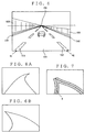
- Figs. 5A - 5C are views for explaining a concrete
example of white-line estimating processing;
- Figs. 6A and 6B are views for explaining the manner of
estimation of white lines;
- Fig. 7 is a view for explaining retrieval-region setting
processing;
- Fig. 8 is a view of the white line estimated by a running
locus or road shape;
- Fig. 9 is a view showing an example of the manner of
determining the position of white lines;
- Fig. 10 is a block diagram of the second embodiment of
the rear monitoring system according to the present
invention;
- Figs. 11A - 11D is a view for explaining changes in the
road image on the rear picked up by a video camera 1; and
- Fig. 12 is a conceptual view of the road image of a speed
way having one-side three lanes.
-
DESCRIPTION OF THE PREFERRED EMBODIMENTS
-
Hereinafter, referring to the drawings, an explanation
will be given of several embodiments of the rear monitoring
system according to the present invention.
Embodiment 1
-
Fig. 2 shows an embodiment of a rear monitoring system
for a vehicle according to the present invention. In Fig,
2, reference numeral 10 denotes an image pick-up section
serving as an image pick-up means. Reference numeral 20
denotes a storage section for storing image data and others.
Reference numeral 30 denotes a data processing section A for
implementing image processing and monitoring a relationship
with other vehicles on the basis of the image information from
the image pick-up section 10. Reference numeral 40 denotes
a warning section for giving a warning. Reference numeral
50 denotes a signal input section for receiving a signal
indicative of the operation information when the running
direction of one's own vehicle is changed.
-
The image pick-up section 10, which may be a video
camera, includes a lens 11a and image plane 11b. The video
camera A11 is attached to the upper or rear side of the trunk
portion on the rear side of a vehicle so that it is oriented
rearward.
-
The video camera A11 is configured to pick up the image
of the road on the rear of one's own vehicle. The video camera
A11 supplies the data D1 of the image thus acquired to a data
processing section A30.
-
The storage section 20 includes a first and a second
frame memory 21 and 22, a front white-line frame memory 21
and a divergent optical flow memory 24. The first and the
second frame memory 21 and 22 temporarily store, as pixel data
D2 and D3, the pixels in a m- by n- matrix (e.g. 512 x 512
pixels and with the luminance in 0 - 255 tones) converted from
the diagonal-rear road image data D1 imaged on the image plane
11b of the video camera A11, and supplies them to the data
processing section A30.
-
These first and the second frame memory 21 successively
store the m x n pixel data D2 and D3 converted from the
diagonal-rear road image picked up at an established period
Δ t in such a manner that it is stored in the first frame memory
21 at timing t, in the second frame memory 22 at timing t +
Δ t , ... ... .
-
The diagonal rear white-line frame memory 23 is composed
of a first and a second diagonal-rear frame memory (not shown).
The diagonal rear white-line frame memory 23 temporarily
stores the white-line data D4 of the front road image
for discriminating one's own lane from the adjacent lane at
a predetermined period Δ t and supplies it to the data
processing section A30. The white-line data D4 are acquired
from the video camera B61 attached to the front of one's own
vehicle and installed in a front monitoring device 60.
-
The front monitoring device serves as a collision
preventing device. The front monitoring device includes a
video camera B61 serving as the front image pick-up means,
a data processing unit B62 for processing the data supplied
from the video camera and a speaker 63 for giving a warning.
Specifically, in the collision-preventing device, the data
processing unit B62 detects the white line to discriminate
the one's own lane from the adjacent lane in the front road
image picked up by the video camera B61, and decides the danger
degree of rear-end collision of the one's own vehicle with
another diagonal-front vehicle which is running on the one's
own lane. On the basis of the result of decision, the speaker
B63 gives a warning. Incidentally, the above white-line data
D4 is taken from the data processing section B62.
-
In this embodiment, the front monitoring device was used
as the collision preventing device 60. However, it may be
used for an adaptive cruise control (ACC). The ACC is
performed in such a way that the one's own vehicle can follow
another vehicle, which runs ahead of the one's own vehicle
at a lower speed than a prescribed speed, while it runs at
maintaining the distance between both vehicles. In this case,
such a vehicle running at the low speed can be detected by
detecting the white line to discriminate the one's own lane
from the adjacent lane on the front (inclusive of front-side
or diagonal front) image picked up by the video camera B61
and the vehicle running on only the one's own lane on the basis
of the thus detected white line.
-
Since the video camera B61 installed in the front
monitoring device can be used for the above purpose without
providing any other separate video camera, the production
cost can be reduced.
-
The data processing A30 includes a CPU 31 operating
along a control program, a ROM 32 for storing the control
program for the CPU 31 and an RAM for temporarily storing the
data required for the operation by the CPU 31.
-
The warning section 40 includes a display 41 and a
speaker 42. The display 41 which may be an LCD displays the
diagonal-rear road image picked up by the video camera A11,
or displays a message when it is decided by the data processing
unit A that there is danger of contact with another vehicle,
thereby visually informing the driver of the danger. The
speaker 42 produces sound such as an audio guidance or an
audible alert. Then it is decided by the data processing
section A30 that there is danger of collision or contact with
another vehicle, the danger is informed the driver by sound.
-
The signal input section 50 includes a light-on
detecting switch 51, a winker (turn signal) detecting switch
52 and a running sensor 53. The light-on detecting switch
51 serves to detect the "on" of a head light by a driver. The
winker detecting switch 52 serves to detect the operation
state and its operation direction of a winker mechanism by
the driver, i.e. turn-around instruction information from a
winker mechanism operated when the driver turns the vehicle
around toward the right or left side. The running sensor 53
serves to detect the running distance of a vehicle.
-
Referring to the flowchart of Fig. 3, an explanation
will be given of the control operation by the data processing
section A30.
-
First, in step SP110, the processing of acquisition of
white-line information is performed by the CPU 31. In this
processing, the white-line data D4 of the front road image
detected by the data processing section B62 is acquired to
estimate the white line of a diagonal-rear road image. The
white-line data of the front road image thus acquired is
stored in the diagonal-front white-line frame memory 23.
-
In step SP120, the processing of acquiring the
diagonal-rear image is performed. In this processing, the
rear road image as shown in Fig. 4 is acquired.
-
This rear road image is an image viewed from one's own
vehicle which is running on a vehicle-dedicated road such as
a speed way. Namely, it is the image directly picked up by
the video camera A11 attached to the rear of the vehicle so
that it is oriented rearward. As seen from Fig. 4, the image
includes a road 500, inner white lines 510, 520 and outer white
lines 530, 540, and side walls 600. The inner white lines
510, 520 are broken lines which are drawn on the road to
discriminate one's own vehicle from adjacent lanes, and
permit a lane change to be made. The outer white lines 530,
540 are continuous solid lines which are drawn on the road
to define side roads and prohibit the lane change. The image
of side walls 600 formed upright on both sides of the road
500 disappears at the center position in a horizontal
direction and a position of 1/3 from above in a vertical
direction. The disappearing point is referred to as "FOE".
-
The data D1 of the rear-diagonal road image thus
acquired are converted into the pixel data D2 which is an image
in a matrix with m-rows and n-columns. The image data D1
are stored in the first frame memory 21 of the storage section
20.
-
The FOE line L indicative of the position of the FOE
in the vertical direction depends on the view angle of the
video camera A11 attached to the rear side of one's own vehicle
so as to be oriented rearward, lens aberration, installing
parameters (height and elevation angle), etc. For example,
it is located at a rear position of 100 meter. The explanation
will be made assuming that the FOE line L is located at the
rear position of 100 meter.
-
In step SP130, the output from the light-on detecting
switch 51 is read to decide whether or not the head light is
"ON" or not. If YES, it is decided that even if the rear road
image is processed, the white line cannot be recognized
because it is now in the nighttime. The processing proceeds
to step SP140 in which white-line estimation is performed by
the CPU 31.
-
Referring to Figs. 5A and 5B, an explanation will be
given of an example of the processing of white-line estimation.
Now it is assumed that the vehicle runs along the line as shown
in Fig. 5A for every period Δ t. Now, the white-line data
D4 detected from the front road image, as shown in Fig. 5B,
have been stored in the diagonal-front white-line frame
memory 23.
-
First, in order to estimate the white lines of the rear
image picked up at the vehicle position at timing t, the
white-line data D4 100 meter ahead of the position of one's
own vehicle at the timing, which is a position of the FOE line
L, is acquired from the diagonal-front white-line memory 23.
For example, if the position of about 100 meter ahead
corresponds to the timing t - 2 Δ t, two frames ago, as a result
of the detection result of the running sensor 53, the white
line data D4 at the timing t - 2 Δ t is acquired. On the basis
of the white-line data D4 at timing t - 2 Δ t, the white lines
will be estimated as shown in Fig. 5C.
-
The estimation of the white lines will be made as follows.
For example, it is assumed that in the white line data D4 of
the front road picked up 100 meter ahead of one's own vehicle,
as shown in Fig. 6A, the line at a relatively near position
is straight whereas that at a far position is curved. In this
case, in the estimated rear road image, as shown in Fig. 6B,
the line at the relatively near position is curved, whereas
that at the far position is straight. It can be also estimated
that the orientation of the curve of the estimated rear road
image is reverse to that of the front road image.
-
Thus, by estimating the white lines on the basis of the
white-line data D4 in the front image picked up by the video
camera B61, the white lines can be easily detected in the
nighttime when the white lines cannot be detected from the
rear road image.
-
Further, since the white data D4 detected by the front
monitoring device 60 is used for estimation, the white lines
can be easily detected with no image processing. After the
white lines are estimated, the processing proceeds to step
SP150.
-
In step SP130, if "NO" (the headlight is "off"), it is
decided that the white lines can be detected from the rear
road image since it is now in the daytime, and hence the
processing proceeds to step SP160. In step SP160, the
processing of setting a retrieval area is performed by the
CPU 31. Referring to Fig. 7, the processing of setting a
retrieval area will be explained below.
-
By the same processing as the white-line estimating
processing in step SP140, a white line H of the rear road image
is estimated. On the basis of the white line H, an area having
a prescribed width and shaded as seen from Fig. 7C is set as
a retrieval area. Instep SP170, the processing of detecting
a white line is performed by the CPU 31. In this white-line
detecting processing, the white line is detected for only the
retrieval area. Therefore, the quantity of the image
processing for detection of the white line is reduced so that
the white line can be easily detected in the daytime.
Thereafter, the processing proceeds to step SP150 in Fig. 3.
-
In step SP150, the processing of setting a monitoring
region is performed. In this monitored region setting
processing, a monitoring region for one's own lane is set
inside region encircled by the white line estimated or
detected in step SP140 or 170, whereas that for the adjacent
lane is set in the region outside the white line and
particularly encircled by the FOE line L. Thereafter, the
processing proceeds to step SP180. In step SP180, the
processing of detecting an optical flow is performed by the
CPU 31.
-
The processing of detecting the optical flow is
performed for each of the monitoring regions set in step
SP150.
Where the monitoring region is set in both adjacent lanes on
both sides of one's own lane, it is picked up later than the
road image stored in the first frame memory 21 by a prescribed
time Δ t. The same monitoring region is set for the road image
stored in the second frame memory 22. The moving direction
and moving distance between each of the points constituting
the road image at timing t and the corresponding points at
timing t + Δ t can be detected as the optical flow.
-
In step SP190, the processing of computing the degree
of danger will be made. In this step, the magnitude (or
length) of the optical flow in a diverging direction from the
FOE is weighted so that it takes a numerical form.
Incidentally, in this processing, with a threshold value set
in several levels, the level of danger may be computed.
-
Instep SP200, on the basis of the degree of danger thus
computed, if it exceeds the threshold value, decision of being
danger is made. Otherwise, if the level of danger exceeds
a prescribed value, decision of being dangerous is made.
-
If the decision of being dangerous is made, in step SP210,
the processing of warning is executed. If the decision of
being not dangerous, the processing is ended. Subsequently,
the processing from step SP110 will be started again.
-
In the processing of warning in step SP210, an audio
signal is sent to the speaker 42 in the warning section 40.
An audio guidance or audible alert is produced so that the
attention of the driver is attracted. In addition, a message
is displayed on the display 41 so that the danger is visually
informed the driver. Upon completion of the warning
processing, the processing from step SP110 is started again.
-
In the above embodiment, although the processing of
estimating the white line was executed in the nighttime, it
can be executed in the daytime to estimate the white line.
-
In the above embodiment, the information on the road
on which one's own vehicle has run is acquired by acquiring
the white line data D4 on the front road image (position
information acquiring means 61). However, it may be acquired
from the position coordinate which can be computed on the
basis of the helm angle (obtained by a helm angel sensor)
and running speed obtained by the running sensor 53 (position
coordinate acquiring means 31b-1).
-
If the running locus R2 composed of points R1 as shown
in Fig. 8 is plotted as a result of acquisition of the
position information, two white line positions W1 and W2
intersecting the outer edge of the rear road image are
connected to the point P which is located at 100 meter behind
along the locus as two curves. These curves are estimated as
white lines.
The white line positions W1 and W2, which are located at
positions very near from the vehicle, can be obtained from
the rear road image in such a manner that light is projected
downward in a degree of glare not sensed by the driver of the
following vehicle.
-
The white line positions W1 and W2 move in accordance
with the helm angle. Therefore, they may be detected by the
image processing for an minimum image processing region which
is defined on the outer periphery of the rear road image
corresponding to the range of the white line moving according
to the helm angle. The image processing is made while
attention is paid to the fact that luminance is stronger at
the two positions intersecting the outer edge of the rear road
image than the other positions. Further, if the white line
positions W1 and W2 according to the helm angle, which can
be sensed by the helm angle sensor attached to the rear
monitoring device, are previously stored, the white line
positions W1 and W2 according to the helm angle.
-
As described above, by estimating the white lines on
the rear road image which distinguish one's own lane from both
adjacent lanes on the basis of the vehicle position
information indicative of the locating coordinate of the
vehicle changing according to the helm angle and running speed
of the vehicle, the white lines on the rear road image can
be easily estimated without making the image processing
by acquisition of the helm angle and running speed regardless
of the daytime and nighttime. Even if the white lines cannot
be detected from the front road image, they can be estimated.
Embodiment 2
-
Referring to the drawings, an explanation will be given
of a rear monitoring device according to the second embodiment
of the present invention. Fig. 10 is a block diagram of the
second embodiment of the rear monitoring device. In Fig. 10,
like reference numerals refer to like elements in the first
embodiment shown in Fig. 2.
-
In Fig. 10, a data processing A30 receives present
position data D7 from a GPS receiver 72 which is an information
acquiring means through a GPS antenna 71 and map data D8 from
a map database 74 which is map storage means.
-
The GPS antenna 71, GPS receiver 72 and map data base
74 are included in a GPS navigation apparatus 70 in which the
map data D8 corresponding to the present position data D7 are
read out from the map data base 74 stored in a large-capacity
memory such as a CD-ROM by the data processing section C73
and displayed on the display 41. Use of the GPS navigation
apparatus intends to reduce the production cost.
-
Referring to Fig. 3, an explanation will be given of
the operation of the rear monitoring system for a vehicle,
i.e. operation of the CPU 30 in the data processing section
30. The same steps as those in the first embodiment will not
be explained in detail. In the second embodiment, the
operation in step SP110 is not performed, and the subsequent
SP120 - SP130 are performed in the same manner as in the first
embodiment. Instep SP130, if the light is "ON", it is decided
that the white line cannot be detected from the rear road image,
and the processing of white line estimation in step SP140 is
performed. Referring to Fig. 9, an example of the white line
estimation in step SP140 will be explained.
-
First, the present position data D7 received by the GPS
receiver are read out. The map data D8 corresponding to the
present position data D7 are read out from the map data base
64. Next, the image of a road shape 100-meter behind from
the present position is acquired on the basis of the read
present position data D7 and map data D8. Assuming that road
shape R2 as shown in Fig. 8 has been plotted, two white line
positions W1 and W2 intersecting the outer edge of the rear
road image are connected to the point P which is located at
100 meter behind along the locus as two curves. These curves
are estimated as white lines.
-
In step 130, if the light is "OFF", it is decided that
the white lines can be detected from the rear image.
Subsequently, in the processing of detection of the white
lines in step SP 160, the white lines constituting both ends
of the lane on which one's own vehicle runs are detected from
the rear-diagonal road map acquired by the video camera A11.
Thereafter, the processing in each of steps SP150 - SP210 will
be executed.