EP1034949B1 - Führungslenker für eine Kraftfahrzeugradaufhängung - Google Patents
Führungslenker für eine Kraftfahrzeugradaufhängung Download PDFInfo
- Publication number
- EP1034949B1 EP1034949B1 EP99125460A EP99125460A EP1034949B1 EP 1034949 B1 EP1034949 B1 EP 1034949B1 EP 99125460 A EP99125460 A EP 99125460A EP 99125460 A EP99125460 A EP 99125460A EP 1034949 B1 EP1034949 B1 EP 1034949B1
- Authority
- EP
- European Patent Office
- Prior art keywords
- suspension link
- supporting sections
- bearing
- suspension
- bearing bore
- Prior art date
- Legal status (The legal status is an assumption and is not a legal conclusion. Google has not performed a legal analysis and makes no representation as to the accuracy of the status listed.)
- Expired - Lifetime
Links
Images


Classifications
-
- B—PERFORMING OPERATIONS; TRANSPORTING
- B60—VEHICLES IN GENERAL
- B60G—VEHICLE SUSPENSION ARRANGEMENTS
- B60G7/00—Pivoted suspension arms; Accessories thereof
- B60G7/001—Suspension arms, e.g. constructional features
-
- B—PERFORMING OPERATIONS; TRANSPORTING
- B60—VEHICLES IN GENERAL
- B60G—VEHICLE SUSPENSION ARRANGEMENTS
- B60G2204/00—Indexing codes related to suspensions per se or to auxiliary parts
- B60G2204/40—Auxiliary suspension parts; Adjustment of suspensions
- B60G2204/41—Elastic mounts, e.g. bushings
-
- B—PERFORMING OPERATIONS; TRANSPORTING
- B60—VEHICLES IN GENERAL
- B60G—VEHICLE SUSPENSION ARRANGEMENTS
- B60G2204/00—Indexing codes related to suspensions per se or to auxiliary parts
- B60G2204/40—Auxiliary suspension parts; Adjustment of suspensions
- B60G2204/416—Ball or spherical joints
-
- B—PERFORMING OPERATIONS; TRANSPORTING
- B60—VEHICLES IN GENERAL
- B60G—VEHICLE SUSPENSION ARRANGEMENTS
- B60G2206/00—Indexing codes related to the manufacturing of suspensions: constructional features, the materials used, procedures or tools
- B60G2206/01—Constructional features of suspension elements, e.g. arms, dampers, springs
- B60G2206/10—Constructional features of arms
- B60G2206/11—Constructional features of arms the arm being a radius or track or torque or steering rod or stabiliser end link
-
- B—PERFORMING OPERATIONS; TRANSPORTING
- B60—VEHICLES IN GENERAL
- B60G—VEHICLE SUSPENSION ARRANGEMENTS
- B60G2206/00—Indexing codes related to the manufacturing of suspensions: constructional features, the materials used, procedures or tools
- B60G2206/01—Constructional features of suspension elements, e.g. arms, dampers, springs
- B60G2206/10—Constructional features of arms
- B60G2206/124—Constructional features of arms the arm having triangular or Y-shape, e.g. wishbone
-
- B—PERFORMING OPERATIONS; TRANSPORTING
- B60—VEHICLES IN GENERAL
- B60G—VEHICLE SUSPENSION ARRANGEMENTS
- B60G2206/00—Indexing codes related to the manufacturing of suspensions: constructional features, the materials used, procedures or tools
- B60G2206/01—Constructional features of suspension elements, e.g. arms, dampers, springs
- B60G2206/80—Manufacturing procedures
- B60G2206/81—Shaping
- B60G2206/8101—Shaping by casting
Definitions
- the invention relates to a guide arm for suspension of motor vehicles, with an at least two-part handlebar body, the handlebar body comprising two elongate support profiles, which are at least two-thirds of their length from each other spaced parallel to each other and at least in contact the environment of a bearing bore of the handlebar body.
- Such a guide arm is known from DE 29 52 176 C2.
- a guide arm consisting of two elongated, cup-shaped and firmly together connected sheet metal parts consists.
- the sheet metal parts have at their ends openings, by or deformed ring collar are reinforced.
- the ring collars are dimensioned that they engage in the assembly of the two sheet metal parts and hold by force closure.
- This leader is especially suitable for small wheel loads.
- he offers the installation effort when mounting in the vehicle no advantages over the conventional, one-piece handlebars.
- the handlebar consists of two identical, mirror images to be arranged press moldings and connecting these parts Bearing element.
- the opposing Preßformmaschine have at one end in each case an annular collar, in the two inner bores a bearing element is pressed.
- this handlebar is especially suitable for small wheel loads. This shows u.a. in that the bearing element in the handlebar no clear having axial fixation.
- the present invention is based on the problem to develop a guide handle that is characterized by a simple Construction, a low production cost and a uncomplicated assembly distinguishes. He should also be responsible for be suitable for large wheel loads.
- the guide arm has one of two elongated support profiles formed handlebar body.
- the support profiles are opposite one Center-plane mirror-symmetrically designed, the middle between the support profiles and normal to the centerlines of at least two of the existing in the support profiles bearing bores is. They are in the assembled state in the area where they are directly touching, a cylindrical cavity concentric is arranged to a bearing bore, wherein the inner diameter of the cavity is greater than the diameter of the corresponding Bearing bore.
- the handlebar body consists of opposite profiles, can easily cavities in the area between the support profiles or outbreaks are arranged without consuming Forging or casting forms arise.
- the handlebar body is comparable to a ladder design.
- the support profiles of the handlebar body are the bars of the Ladder, while the axes or the screw connections of the bearing body received bearings, e.g. for the wheel carrier, a damper, a vehicle spring or a strut the treads form.
- the axes or the screw connections are simultaneous stiffening and supporting components of the guide arm, whereby fasteners can be saved.
- FIG. 1 shows one formed from two support profiles (11, 12) Handlebar body (1) of a guide arm.
- the handlebar body (1) connects as part of a suspension, for example a wheel of an independent suspension with the vehicle body. He has the bearing holes (21) and (24), where he pivotally mounted on the body via the Anlenkbohrung (24) is, cf. Figure 3, while he over the Radyeslagerbohrung (21) articulates the wheel carrier, cf. FIG. 2.
- the handlebar body (1) takes, for example, the lower Anlenkstellen a shock absorber and a vehicle spring in the bearing bores (22) and (23).
- FIG. 2 shows the Damper bearing in the damper bearing bore (22). The shock absorber and the suspension are not shown.
- the link body (1) has in the embodiment two to each other mirror-symmetrically designed support profiles (11, 12).
- the symmetry plane is one between the support profiles (11, 12) lying median plane (2), which also normal or perpendicular to at least part of the center lines of the bearing bores (21-24) is aligned.
- the support profiles have over, for example the majority of their length an I-shaped cross-sectional profile. In the area of the bearing bores (21-24) goes the I-profile partly in a rectangular profile over. There are the bearing holes (21-24) through tubular or annular material accumulations (26) reinforced.
- the I-cross-sectional profile goes to FIG 1 and 3 in the direction of the Anlenkbohrung (24) under a Reduction of the profile width in a C-profile over.
- the profile opening is oriented to the outside.
- the center lines of all bearing bores (21-24) are only an example parallel to each other and in one plane.
- the distance between the support profiles is over the handlebar body length e.g. to adapt to specific Anlenkstellendimensionen and loads arbitrarily variable.
- the cross-sectional profile height and profile wall thickness variable.
- FIG 2 the wheel-side end of the handlebar body (1) is shown.
- the ends of the support profiles (11, 12) have in the area of Raditatilagerbohrung (21) each one of the in the Level (2) lying parting line of oriented coaxial depression (13, 14), both together a cylindrical interior form.
- the swivel joint consists of a Swivel joint body (31) with ball section, a sleeve (32) and a one or more parts used between these parts Elastomer body shell (33).
- the sleeve (32) the maximum twice as long as the sum of the two depressions (13, 14).
- the support profiles (11, 12) is the damper bearing bore (22) whose edges through the support reinforcements (26) are reinforced.
- a Screw (54) on which a sleeve (52) supports.
- the sleeve (52) can with a small Schwenkwinkel pad of the shock absorber the Have function of a spacer sleeve.
- the support profiles (11, 12) rigidly connected.
- the sleeve (52) inserted positively or non-positively held by an elastomeric body in a damper rod eye (51).
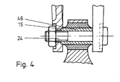
- FIG. 4 also shows the vehicle body-side end of the vehicle body Arm body. Again, the support profiles (11, 12) over a sleeve (46) screwed together.
- the sleeve (46) is in Compared to the sleeve (42) of Figure 3 longer. She sticks out with her both ends in depressions (15). The latter are for example arranged concentrically to the Anlenkbohrung (24).
- the sleeve (46) sits for example with its cylindrical outer contour by means of a Querpreßsitzes in the depressions (15) so that they Supporting profiles (11, 12) positively connects.
Landscapes
- Engineering & Computer Science (AREA)
- Mechanical Engineering (AREA)
- Steering Devices For Bicycles And Motorcycles (AREA)
- Axle Suspensions And Sidecars For Cycles (AREA)
- Vehicle Body Suspensions (AREA)
- Steering-Linkage Mechanisms And Four-Wheel Steering (AREA)
Description
- Figur 1:
- Lagerkörper in dimetrischer Darstellung;
- Figur 2:
- Führungslenkerabschnitt mit Radträger- und Dämpferankopplung;
- Figur 3:
- Führungslenkerabschnitt mit der Anlenkung am Fahrzeugaufbau.
- Figur 4:
- wie Figur 4, jedoch mit längerer Hülse.
- 1
- Führungslenker, Lenkerkörper
- 2
- Mittelebene, Symmetrieebene
- 11, 12
- Tragprofile
- 13, 14, 15
- Einsenkungen, Hohlraum
- 21
- Radträgerlagerbohrung, Lagerbohrung
- 22
- Dämpferlagerbohrung, Lagerbohrung
- 23
- Federlagerbohrung, Lagerbohrung
- 24
- Anlenkbohrung, Lagerbohrung
- 26
- Auflageverstärkungen, rohrförmig Material anhäufungen
- 31
- Schwenkgelenkkörper, Radträgerseite
- 32
- Hülse
- 33
- Elastomerkörperschale
- 41
- Anlenkblock am Fahrzeugaufbau
- 42
- Hülse
- 43
- Elastomerkörper
- 44
- Schraube
- 45
- Mutter
- 46
- Hülse, lang
- 51
- Dämpferstangenauge
- 52
- Hülse
- 53
- Elastomerkörper
- 54
- Schraube
- 55
- Mutter
Claims (4)
- Führungslenker für Radaufhängungen von Kraftfahrzeugen, mit einem mindestens zweiteiligen Lenkerkörper, wobei der Lenkerkörper zwei längliche Tragprofile umfaßt, die über mindestens zwei Drittel ihrer Länge voneinander beabstandet parallel zueinander liegen und sich mindestens in der Umgebung einer Lagerbohrung des Lenkerkörpers kontaktieren,wobei die Tragprofile (11, 12) gegenüber einer Mittelebene (2) spiegelsymmetrisch gestaltet sind, die mittig zwischen den Tragprofilen (11, 12) und normal zu den Mittellinien von mindestens zwei Lagerbohrungen (21-24) liegt, dadurch gekennzeichnet, daßdie Tragprofile (11, 12) im montierten Zustand in dem Bereich, in dem sie sich direkt berühren, einen zylindrischen Hohlraum (13, 14) haben, der konzentrisch zu einer Lagerbohrung (21) angeordnet ist, wobei der Innendurchmesser des Hohlraums (13, 14) größer ist, als der Durchmesser der entsprechenden Lagerbohrung (21).
- Führungslenker gemäß Anspruch 1, dadurch gekennzeichnet, daß der Lenkerkörper (1) mindestens drei parallel zueinander ausgerichtete Lagerbohrungen (21-24) aufweist.
- Führungslenker gemäß Anspruch 1, dadurch gekennzeichnet, daß die Tragprofile (11, 12) in den Bereichen von zumindest einem Teil der Lagerbohrungen (22-24) durch dort zumindest bereichs weise vorhandene Materialanhäufung (26) verstärkt ausgebildet sind.
- Führungslenker gemäß Anspruch 1, dadurch gekennzeichnet, daß die Tragprofile (11, 12) zumindest über einen Teil ihrer Länge einen I-förmigen Querschnitt haben.
Applications Claiming Priority (2)
| Application Number | Priority Date | Filing Date | Title |
|---|---|---|---|
| DE19911021A DE19911021B4 (de) | 1999-03-12 | 1999-03-12 | Führungslenker für eine Kraftfahrzeugradaufhängung |
| DE19911021 | 1999-03-12 |
Publications (3)
| Publication Number | Publication Date |
|---|---|
| EP1034949A2 EP1034949A2 (de) | 2000-09-13 |
| EP1034949A3 EP1034949A3 (de) | 2001-03-28 |
| EP1034949B1 true EP1034949B1 (de) | 2003-05-14 |
Family
ID=7900714
Family Applications (1)
| Application Number | Title | Priority Date | Filing Date |
|---|---|---|---|
| EP99125460A Expired - Lifetime EP1034949B1 (de) | 1999-03-12 | 1999-12-21 | Führungslenker für eine Kraftfahrzeugradaufhängung |
Country Status (3)
| Country | Link |
|---|---|
| US (1) | US6305699B1 (de) |
| EP (1) | EP1034949B1 (de) |
| DE (2) | DE19911021B4 (de) |
Families Citing this family (11)
| Publication number | Priority date | Publication date | Assignee | Title |
|---|---|---|---|---|
| US20040165147A1 (en) * | 2001-11-13 | 2004-08-26 | Della Vecchia Michael A. | Determining iris biometric and spatial orientation of an iris in accordance with same |
| NO315192B1 (no) * | 2002-03-12 | 2003-07-28 | Kongsberg Automotive Asa | Kobling |
| DE10219708A1 (de) * | 2002-05-02 | 2003-11-13 | Zf Lemfoerder Metallwaren Ag | Dreiecklenker |
| ATE509791T1 (de) * | 2004-11-26 | 2011-06-15 | Volvo Lastvagnar Ab | Befestigungssystem für eine v-strebe in einem grossen fahrzeug |
| US7429054B1 (en) | 2005-12-14 | 2008-09-30 | Heckethorn Products, Inc. | Non-drop torsion bar bracket and assembly |
| DE102008001157A1 (de) * | 2008-04-14 | 2009-11-05 | Zf Friedrichshafen Ag | Gelenk- und/oder Lageranordnung |
| DE102014201057A1 (de) * | 2014-01-22 | 2015-07-23 | Zf Friedrichshafen Ag | Bauteilanbindung mit querkraftabstützender Stützfläche |
| US9751370B2 (en) * | 2014-08-29 | 2017-09-05 | Niwot Corporation | Adjustable control arm |
| DE102015209845A1 (de) * | 2015-05-28 | 2016-12-01 | Zf Friedrichshafen Ag | Querlenker |
| DE102017213564A1 (de) * | 2017-08-04 | 2019-02-07 | Zf Friedrichshafen Ag | Dreipunktlenker und Herstellungsverfahren für einen Dreipunktlenker |
| KR102750673B1 (ko) * | 2020-03-23 | 2025-01-06 | 현대자동차주식회사 | 차량 현가장치용 인슐레이터 및 그 제조 방법 |
Family Cites Families (19)
| Publication number | Priority date | Publication date | Assignee | Title |
|---|---|---|---|---|
| US2122476A (en) * | 1936-03-20 | 1938-07-05 | John W Leighton | Individual suspension |
| US2226406A (en) * | 1936-11-18 | 1940-12-24 | Goodrich Co B F | Vehicle wheel mounting |
| DE758202C (de) * | 1940-09-06 | 1954-04-22 | Carl F W Borgward | Gabelartiger bzw. dreieckfoermiger Lenker fuer unabhaengig gefuehrte Raeder von Kraftfahrzeugen |
| US2299935A (en) * | 1941-02-24 | 1942-10-27 | Chrysler Corp | Control arm |
| DE1642820U (de) * | 1948-10-01 | 1952-08-28 | Daimler Benz Ag | Radaufhaengung, insbesondere fuer kraftfahrzeuge. |
| US2652264A (en) * | 1951-04-03 | 1953-09-15 | Thompson Prod Inc | Steering knuckle |
| US2707100A (en) * | 1952-06-18 | 1955-04-26 | Smith Corp A O | Control arm for vehicle wheel suspension |
| US2876018A (en) * | 1955-08-12 | 1959-03-03 | American Motors Corp | Vehicle wheel suspension |
| BE556782A (de) * | 1956-06-25 | |||
| US2913251A (en) * | 1958-02-17 | 1959-11-17 | Thompson Ramo Wooldridge Inc | Self-adjusting pivot bushing for vehicle suspension |
| DE2952176C2 (de) * | 1979-12-22 | 1986-04-10 | Daimler-Benz Ag, 7000 Stuttgart | Führungslenker für Radaufhängungen von Kraftfahrzeugen |
| US4778199A (en) * | 1986-05-05 | 1988-10-18 | The B. F. Goodrich Company | Suspension system |
| US5515246A (en) * | 1988-12-16 | 1996-05-07 | Mag Instrument, Inc. | Holder clamp assembly |
| DE3921468C1 (en) * | 1989-06-30 | 1990-05-23 | Bayerische Motoren Werke Ag, 8000 Muenchen, De | Link for car wheel suspensions - has annular collars on two sheet metal parts, both collars surrounding bearing member |
| DE4004679A1 (de) * | 1990-02-15 | 1991-08-22 | Brueninghaus Krupp Gmbh | Dreieckslenker fuer nutzkraftfahrzeuge |
| GB2243125B (en) * | 1990-04-12 | 1994-03-23 | Charan Nelms | Vehicle suspension |
| JPH0454334A (ja) * | 1990-06-20 | 1992-02-21 | Bridgestone Corp | ブラケット一体型防振装置及びその製法 |
| US5165306A (en) * | 1990-10-04 | 1992-11-24 | Maclean-Fogg Company | Vehicle stabilizer bar end link |
| US5238262A (en) * | 1991-11-21 | 1993-08-24 | Nunes Anthony M | Bracket and bushing assembly for walking beam of vehicle wheel suspension system |
-
1999
- 1999-03-12 DE DE19911021A patent/DE19911021B4/de not_active Expired - Fee Related
- 1999-12-21 EP EP99125460A patent/EP1034949B1/de not_active Expired - Lifetime
- 1999-12-21 DE DE59905550T patent/DE59905550D1/de not_active Expired - Fee Related
-
2000
- 2000-03-10 US US09/523,247 patent/US6305699B1/en not_active Expired - Fee Related
Also Published As
| Publication number | Publication date |
|---|---|
| DE19911021A1 (de) | 2000-09-21 |
| US6305699B1 (en) | 2001-10-23 |
| DE19911021B4 (de) | 2005-09-15 |
| DE59905550D1 (de) | 2003-06-18 |
| EP1034949A2 (de) | 2000-09-13 |
| EP1034949A3 (de) | 2001-03-28 |
Similar Documents
| Publication | Publication Date | Title |
|---|---|---|
| DE19932678B4 (de) | Stabilisatorgestänge und Gelenk hierfür | |
| EP0494393B1 (de) | Unabhängige Radaufhängung | |
| WO2008098550A1 (de) | Starrachse für ein nutzkraftfahrzeug | |
| DE19911021B4 (de) | Führungslenker für eine Kraftfahrzeugradaufhängung | |
| DE19623630A1 (de) | Kugelgelenk mit Fassung | |
| DE2739250C2 (de) | Scharniergelenk für ein Federgehänge | |
| DE69103380T2 (de) | Hydraulisches Buchsenlager gegen Schwingungen. | |
| DE102015210915B4 (de) | Lenker für eine Radaufhängung eines Fahrzeugs | |
| DE2623870A1 (de) | Elastisches lenkerlager fuer radaufhaengungen von kraftfahrzeugen | |
| DE19580267B4 (de) | Anordnung zur Aufhängung eines gefederten Fahrzeug-Fahrerhauses an einem Fahrzeugrahmen | |
| EP4119368B1 (de) | Gelenklager für die abstützung eines fahrzeug-lenkerarms | |
| EP2423532B1 (de) | Stahlgummibuchse | |
| DE4215627C1 (en) | Bearing for car wheel track rod - has axial bearing bush member formed as part of bearing bush assembly, which has clamping ring and engages another busy part | |
| DE1916578A1 (de) | Lenkgestaenge fuer Kraftfahrzeuge | |
| DE19923698A1 (de) | Querlenker | |
| DE102015210151A1 (de) | Verfahren zur Montage der Schwingungsdämpfer eines zweispurigen zweiachsigen Fahrzeugs | |
| DE10329069B4 (de) | Vibrationsisolierende Buchse | |
| DE102015210917A1 (de) | Gelenkverbindung und Anordnung zur Aufhängung eines Rades | |
| DE10050773B4 (de) | Achsaufhängung | |
| DE4421096A1 (de) | Betätigungseinrichtung für Kraftfahrzeugaufhängungen | |
| EP3665066B1 (de) | Radaufhängung | |
| DE4215195A1 (de) | Elastische Lagerung eines Stützarmes | |
| EP1036677B1 (de) | Radaufhängung für ein Kraftfahrzeug | |
| EP1008781B1 (de) | Gelenklager, insbesondere Federaugenlager | |
| DE102014200076A1 (de) | Schwenklager für eine Kraftfahrzeugradaufhängung |
Legal Events
| Date | Code | Title | Description |
|---|---|---|---|
| PUAI | Public reference made under article 153(3) epc to a published international application that has entered the european phase |
Free format text: ORIGINAL CODE: 0009012 |
|
| AK | Designated contracting states |
Kind code of ref document: A2 Designated state(s): DE FR GB IT |
|
| AX | Request for extension of the european patent |
Free format text: AL;LT;LV;MK;RO;SI |
|
| PUAL | Search report despatched |
Free format text: ORIGINAL CODE: 0009013 |
|
| AK | Designated contracting states |
Kind code of ref document: A3 Designated state(s): AT BE CH CY DE DK ES FI FR GB GR IE IT LI LU MC NL PT SE |
|
| AX | Request for extension of the european patent |
Free format text: AL;LT;LV;MK;RO;SI |
|
| 17P | Request for examination filed |
Effective date: 20010322 |
|
| AKX | Designation fees paid |
Free format text: DE FR GB IT |
|
| GRAH | Despatch of communication of intention to grant a patent |
Free format text: ORIGINAL CODE: EPIDOS IGRA |
|
| GRAH | Despatch of communication of intention to grant a patent |
Free format text: ORIGINAL CODE: EPIDOS IGRA |
|
| GRAA | (expected) grant |
Free format text: ORIGINAL CODE: 0009210 |
|
| AK | Designated contracting states |
Designated state(s): DE FR GB IT |
|
| REG | Reference to a national code |
Ref country code: GB Ref legal event code: FG4D Free format text: NOT ENGLISH |
|
| REF | Corresponds to: |
Ref document number: 59905550 Country of ref document: DE Date of ref document: 20030618 Kind code of ref document: P |
|
| GBT | Gb: translation of ep patent filed (gb section 77(6)(a)/1977) | ||
| ET | Fr: translation filed | ||
| PLBE | No opposition filed within time limit |
Free format text: ORIGINAL CODE: 0009261 |
|
| STAA | Information on the status of an ep patent application or granted ep patent |
Free format text: STATUS: NO OPPOSITION FILED WITHIN TIME LIMIT |
|
| 26N | No opposition filed |
Effective date: 20040217 |
|
| PGFP | Annual fee paid to national office [announced via postgrant information from national office to epo] |
Ref country code: GB Payment date: 20041213 Year of fee payment: 6 Ref country code: FR Payment date: 20041213 Year of fee payment: 6 |
|
| PG25 | Lapsed in a contracting state [announced via postgrant information from national office to epo] |
Ref country code: IT Free format text: LAPSE BECAUSE OF NON-PAYMENT OF DUE FEES Effective date: 20051221 Ref country code: GB Free format text: LAPSE BECAUSE OF NON-PAYMENT OF DUE FEES Effective date: 20051221 |
|
| GBPC | Gb: european patent ceased through non-payment of renewal fee |
Effective date: 20051221 |
|
| PG25 | Lapsed in a contracting state [announced via postgrant information from national office to epo] |
Ref country code: FR Free format text: LAPSE BECAUSE OF NON-PAYMENT OF DUE FEES Effective date: 20060831 |
|
| REG | Reference to a national code |
Ref country code: FR Ref legal event code: ST Effective date: 20060831 |
|
| PGFP | Annual fee paid to national office [announced via postgrant information from national office to epo] |
Ref country code: DE Payment date: 20081219 Year of fee payment: 10 |
|
| PG25 | Lapsed in a contracting state [announced via postgrant information from national office to epo] |
Ref country code: DE Free format text: LAPSE BECAUSE OF NON-PAYMENT OF DUE FEES Effective date: 20100701 |