EP1033308A1 - Verfahren zum Überziehen flacher Körper geringer Dicke mit aufschrumpfbaren Folienschlauchabschnitten und Vorichtung zur Durchführung des Verfahrens - Google Patents
Verfahren zum Überziehen flacher Körper geringer Dicke mit aufschrumpfbaren Folienschlauchabschnitten und Vorichtung zur Durchführung des Verfahrens Download PDFInfo
- Publication number
- EP1033308A1 EP1033308A1 EP00103700A EP00103700A EP1033308A1 EP 1033308 A1 EP1033308 A1 EP 1033308A1 EP 00103700 A EP00103700 A EP 00103700A EP 00103700 A EP00103700 A EP 00103700A EP 1033308 A1 EP1033308 A1 EP 1033308A1
- Authority
- EP
- European Patent Office
- Prior art keywords
- conveyor
- flat
- small thickness
- shrinkable
- face
- Prior art date
- Legal status (The legal status is an assumption and is not a legal conclusion. Google has not performed a legal analysis and makes no representation as to the accuracy of the status listed.)
- Granted
Links
- 238000000034 method Methods 0.000 title claims abstract description 15
- 239000011888 foil Substances 0.000 claims abstract description 11
- 230000001360 synchronised effect Effects 0.000 claims description 6
- 238000004806 packaging method and process Methods 0.000 abstract description 19
- 238000007789 sealing Methods 0.000 abstract description 3
- 238000006073 displacement reaction Methods 0.000 abstract 1
- 230000032258 transport Effects 0.000 description 5
- 238000000926 separation method Methods 0.000 description 4
- 230000006978 adaptation Effects 0.000 description 2
- 239000002313 adhesive film Substances 0.000 description 2
- 239000000463 material Substances 0.000 description 2
- 206010043183 Teething Diseases 0.000 description 1
- 239000011248 coating agent Substances 0.000 description 1
- 238000000576 coating method Methods 0.000 description 1
- 239000002537 cosmetic Substances 0.000 description 1
- 239000002184 metal Substances 0.000 description 1
- 238000012856 packing Methods 0.000 description 1
- 239000000843 powder Substances 0.000 description 1
- 229920006300 shrink film Polymers 0.000 description 1
- 230000036346 tooth eruption Effects 0.000 description 1
Images


Classifications
-
- B—PERFORMING OPERATIONS; TRANSPORTING
- B65—CONVEYING; PACKING; STORING; HANDLING THIN OR FILAMENTARY MATERIAL
- B65B—MACHINES, APPARATUS OR DEVICES FOR, OR METHODS OF, PACKAGING ARTICLES OR MATERIALS; UNPACKING
- B65B25/00—Packaging other articles presenting special problems
- B65B25/008—Packaging other articles presenting special problems packaging of contact lenses
-
- B—PERFORMING OPERATIONS; TRANSPORTING
- B65—CONVEYING; PACKING; STORING; HANDLING THIN OR FILAMENTARY MATERIAL
- B65B—MACHINES, APPARATUS OR DEVICES FOR, OR METHODS OF, PACKAGING ARTICLES OR MATERIALS; UNPACKING
- B65B13/00—Bundling articles
- B65B13/02—Applying and securing binding material around articles or groups of articles, e.g. using strings, wires, strips, bands or tapes
- B65B13/022—Applying preformed bands of continuous-ring form, e.g. elastic
-
- B—PERFORMING OPERATIONS; TRANSPORTING
- B65—CONVEYING; PACKING; STORING; HANDLING THIN OR FILAMENTARY MATERIAL
- B65B—MACHINES, APPARATUS OR DEVICES FOR, OR METHODS OF, PACKAGING ARTICLES OR MATERIALS; UNPACKING
- B65B53/00—Shrinking wrappers, containers, or container covers during or after packaging
- B65B53/02—Shrinking wrappers, containers, or container covers during or after packaging by heat
Definitions
- the invention relates to a method for covering flat bodies less Thickness with shrinkable film tube sections.
- German Offenlegungsschrift 39 25 842 is a procedure for Equipping vessels in equipment machines, especially for attachment of equipment material on the head and neck area of bottles become the case during the entire furnishing process optional along their transport route through the equipment machine alternating on their floor and head or on the floor and an area of the The lateral surface is centered on the carrier carrying the vessels become.
- This also makes a device with a feed conveyor a transfer device a carrier with a closed orbit with at least a rotatable turntable that supports the vessels on the bottom, one that can be lifted and lowered in a controlled manner and engages the head of the vessels Centering device, a delivery device and a discharge conveyor, wherein in Area of the transporter at least one equipment station for attachment of equipment is arranged on vessels, become known, wherein a controllable independently of the first centering device with the Transporter co-moving second centering device is provided with a region of the lateral surface of the vessel to be equipped in contact can be brought and this holds on the turntable.
- One such method and device is coating flat body of small thickness with shrinkable film tube sections not applicable because such objects are unstable and insofar as a safe covering with shrinkable film tube sections not possible.
- the present Invention Based on the state of the art that has become known, the present Invention based on the object in sealed flat packaging small thickness with valuable content a seal break recognizable safely before a purchase.
- This task is done with a procedure solved according to the invention in that the flat body transports lying initially in the area of its end face at 180 degrees to each other Place and locked orthogonal to its direction of progress is that then towards the connecting line between the two Place the shrinkable piece of film tube over the flat body to a given position in relation to at least one position of the Front surface reduced during synchronous further transport of the flat body Thickness is pushed and that the film is then exposed to heat is shrunk.
- One embodiment of the method according to the invention is that can be shrink-fitted at the same time, starting from the two points on the end face Foil sections are pushed over the flat body and then be shrunk on.
- This configuration according to the invention is to be used for bodies with a flat rim.
- Such Processing device solves the basis of the invention Task also and ensures that a constant one Sealing flat body of small thickness to be sold enables is done in a single operation, in which the position of the body always remains stable.
- this processing device is about also achieved for the first time that the end face of the invention flat body of small thickness when shrinking on pieces of film tube then practically completely sealed when the film tube piece flat bodies of small thickness protrude in the slide-open direction, i.e. if a piece of film tube is pushed on, the length of which is greater than that Length of the connecting line between the two shifted by 180 degrees End faces, are also suitable as rotating conveyors, both Chain conveyors, transport belts and toothed belts made of metal and / or Plastic.
- each transverse holding device carries a guide extension that the guiding process in one between the leading and the trailing Run of the at least one outer endless conveyor also arranged circumferential guideway.
- Claim 5 protected that the support units of the middle Conveyor for the flat bodies of small thickness per carrying unit at least two supports have that the supports against each other, in their mutual Altitude, in their mutual latitude, in their mutual Length distance and at least in its height to the horizontal running leading strand of the endlessly rotating conveyor adjustable are and that the supports on the left and right of the one rotating conveyor are arranged.
- Such an embodiment of the subject matter of the invention with essentially three adjacent conveyors it also makes it possible Objects that are not only thin but also thin horizontal extension to seal securely.
- protection is provided according to claim 6, that with multi-strand medium conveyors with horizontal leading dreams each conveyor carries an adjustable support.
- a such configuration is particularly applicable to large flat Bodies.
- Claim 8 proposed that the auxiliary mandrel in its heights and width dimensions part of the end face of the flat body in its holding area corresponds and that with the end face of the flat body the front of the auxiliary mandrel comes into contact with a small thickness Part of the largest extent of the end face of the body in the conveying direction and its greatest thickness is adapted.
- the auxiliary mandrels on the object to be sealed can be the inventive device practically every body including its Adjust body contour.
- Claim 8 protected that toothed sliding devices and toothed auxiliary mandrel surfaces are provided. By arranging Teething is a clear pushing on of the shrinkable film guaranteed the item safely.
- a processing device 1 consists essentially of a middle conveyor 2, which is delimited by two outer conveyors 3, 4 and an adjoining shrink tunnel 5, in which ashrinking of film tube sections 6 on flat bodies less Thickness 7 is performed.
- the flat bodies are smaller Thickness 7, for example, from narrow oblong a rectangular cross section owning packing units 8, which at a separation point 9 in an upper housing part 10 and a lower housing part 11 can be separated.
- the support units 13 are height and side adjustable, so that even flat bodies of small thickness, which, for example, in their In the longitudinal direction, however, they are horizontal and conical be aligned orthogonally to the double chain conveyor 12, so that later when the packaging units 8 are taken over by holding devices 14, 15 (see FIG. 4) is guaranteed.
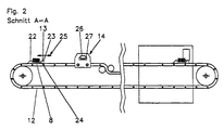
- the double chain conveyor 12 which is a roller chain or link chain conveyor or can be a toothed belt conveyor with carrying units 13, as shown in Figure 2 moved down to the area of Shrink tunnel 5, the packaging units then provided with film tube sections 6 8 resume.
- the double chain conveyor 12 will then then as an endless rotating conveyor behind the shrink tunnel 5 returned to the starting point 2a of the middle conveyor.
- the middle conveyor in the area of position 19 as an endless rotating Conveyors are immediately returned to starting point 2a. In this The trap then becomes independent of the middle conveyor 3 in the area 20 another middle conveyor 21 as the endless rotating conveyor Load shrink tunnel 5 with packaging units 8, which film tube sections 6 carry and empty.
- the support unit 13 consists of a firmly arranged on the chain strand 12a prism 22 and from one of this spaced movable prism 23, which has an oblique leading edge 24 has and so adjustable according to a double arrow 25 is that a conical shape of the surface of the packaging unit 8 can be taken into account.
- shell-shaped packaging units are used, which are also to be regarded as flat bodies of small thickness, it is possible the movable on the two chain strands 12a and 12b Adjust prisms 23 so that a secure support for the shells is given so that in the transfer area of position 19, the holding devices certainly the end face in the area of the horizontal circumferential Can take hold of the shell.
- the holding device 14 is also shown in dashed form and at the same time there is one connected to the holding device 14 rectangular auxiliary mandrel 26 shown. With this in cross section rectangular auxiliary mandrel 26 acts also a rectangular sliding device 27 together.
- the packaging unit 8 is surrounded by a shrink film, which guarantees that a The seal can also be broken by pushing back the film tube section occurs in the direction of the smaller rectangular cross section and thus an absolute security when buying such sealed Packaging units 8 is given for integrity.
- FIG. 3 shows a further form of the holding device 14, 15.
- This holding device is guided in two guide pins 16, 16a, the guide pin 16a is guided in an elongated hole 28 of the holding device 14, 15.
- This slot 28 is used to circulate the endlessly circulating Conveyor change in distance of the guide bolts during rotation Balance gears.
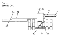
- Figure 4 shows a guide of the holding device 14, 15 and simultaneously a guide of the sliding device 27.
- a body 29 is the located between the roller chains of the outer conveyors 35, 36 with a Provide guideway 30 in which a guide extension 31 of the holding device 14 or 15 is performed.
- the sliding device 27 is another Guide 23 inevitably moves.
- the sliding device 27 runs in simplest form with one end 34 and in the further guide 33 the guide 33 is designed in the conveying direction as a gable roof-shaped guide, so that the pushing device 27 is forced to move forward and thus a pushing off of the film tube section 6 from the auxiliary mandrel 32 happens to the body and then an inevitable withdrawal the sliding device 22 is guaranteed when the film tube section 6 was pushed over the packaging unit 8.
- Figures 1 to 4 illustrated embodiments show the possibility of postponing of film tube sections 6 from one side a flat body of small thickness 7. However, it also falls under the Scope of the invention if in the area of the other outer conveyor 4th further guides 33 are also provided and replaceable there Auxiliary mandrels for other surfaces, for example shell-like Containers with different diameters can be provided.
- the shrinkable piece of film tube up to a given position in relation to at least a point of the end face during the synchronous further transport of the Sliding flat bodies of small thickness can also be flat Close body securely, which both have several separation points in the area the end face as well as several separation points in the area of the surface have for example for the introduction of refill material in a flat body of small thickness.
Landscapes
- Engineering & Computer Science (AREA)
- Mechanical Engineering (AREA)
- Containers And Plastic Fillers For Packaging (AREA)
- Lining Or Joining Of Plastics Or The Like (AREA)
- Laminated Bodies (AREA)
- Shaping By String And By Release Of Stress In Plastics And The Like (AREA)
- Closing Of Containers (AREA)
Abstract
Description
- Figur 1
- eine Draufsicht auf eine Verarbeitungseinrichtung zur Erläuterung des erfinderischen Verfahrens
- Figur 2
- einen Schnitt A-A durch die Verarbeitungseinrichtung gemäß Fig. 1 mit dort nicht dargestellten Einzelheiten
- Figur 3
- einen weiteren Schnitt B-B durch die Verarbeitungseinrichtung gemäß Fig. 1 mit dort nicht dargestellten Einzelheiten und
- Figur 4
- einen weiteren Schnitt C-C durch die Verarbeitungseinrichtung gemäß Fig. 1 mit dort nicht dargestellten Einzelheiten.
Claims (8)
- Verfahren zum Überziehen flacher Körper geringer Dicke mit aufschrumpfbaren Folienschlauchabschnitten dadurch gekennzeichnet, daß der flache Körper geringer Dicke liegend transportiert zunächst im Bereich seiner Stirnfläche an um 180 Grad gegeneinander verschobene Stellen und orthogonal zu seiner Fortschrittsrichtung arretiert wird, daß anschließend in Richtung der Verbindungslinie zwischen beiden Stellen über den flachen Körper das aufschrumpfbare Folienschlauchstück bis zu einer vorgegebenen Postition in Bezug zu mindestens einer Stelle der Stirnfläche während synchronem Weitertransports des flachen Körpers geringer Dicke geschoben und daß anschließend die Folie durch Wärmeeinwirkung aufgeschrumpft wird.
- Verfahren nach Anspruch 1 dadurch gekennzeichnet, daß gleichzeitig ausgehend von den beiden Stellen der Stirnfläche aufschrumpfbare Folienschlauchabschnitte über den flachen Körper geschoben werden und anschließend auf den Körper aufgeschrumpft werden.
- Verarbeitungseinrichtung für aufschrumpfbare Folienschläuche mit Fördereinrichtungen für deren Öffnung, Abtrennung und Zuführung der geöffneten Abschnitte zum Überziehen flacher Körper geringer Dicke zur Durchführung des Verfahrens nach Anspruch 1 und/oder 2 dadurch gekennzeichnet, daß mindestens drei nebeneinander in gleicher Höhe angeordnete mit synchroner Geschwindigkeit mit ihren vorlaufenden Trumen horizontal umlaufende Förderer vorgesehen sind, daß der zwischen den beiden äußeren Förderern angeordnete mittlere Förderer Trageeinheiten für zu überziehende flache Körper geringer Dicke besitzt, daß die beiden äußeren Förderer zu ihrer Förderrichtung quer verlaufende Halteeinrichtungen tragen, daß mindestens einer der beiden äußeren Förderer Führungen für eine Querbewegung der querverlaufenden Halteeinrichtungen besitzt, daß mindestens diese Halteeinrichtung gleichzeitig als Hilfsdorne für die geöffneten Abschnitte der aufschrumpfbaren Folienschläuche ausgebildet sind, daß mit jedem Hilfsdorn eine Schiebeeinrichtung für das aufschrumpfbare Folienschlauchstück verbunden ist, daß die Schiebeeinrichtung in Abhängigkeit einer sich längs der Förderrichtung neben mindesten dem einen äußeren Förderer erstreckenden weiteren Führung quer zur Förderrichtung vor-und zurückbewegt wird und daß während des Aufschiebens des aufschrumpfbaren Folienschlauchstücks der flache Körper geringer Dicke frei vom mittleren Förderer lediglich von den Halteeinrichtungen getragen wird und daß anschließend der Körper einschließlich aufgeschobenem aufschrumpfbaren Folienschlauchstück einem Schrumpftunnel zugeführt wird.
- Vorrichtung nach Anspruch 3 dadurch gekennzeichnet, daß jede querverlaufende Halteeinrichtung einen Führungsfortsatz trägt, daß der Führungsfortsatz in einer zwischen dem vorlaufenden und dem rücklaufenden Trum des mindestens einen äußeren endlosen Förderers angeordneten ebenfalls umlaufenden Führungsbahn verläuft.
- Vorrichtung nach einem oder mehreren der vorhergehenden Ansprüche dadurch gekennzeichnet, daß die Trageinheiten des mittleren Förderers für die flachen Körper geringer Dicke je Trageinheit mindestens zwei Stützen besitzen, daß die Stützen gegeneinander, in ihrer gegenseitigen Höhenlage, in ihrem gegenseitigen Breitenabstand, in ihrem gegenseitigen Längenabstand und mindestens in ihrer Höhenlage zu den horizontal verlaufenden vorlaufendem Trum des endlos umlaufenden Förderers verstellbar sind und daß die Stützen links und rechts an der einen umlaufenden Förderer angeordnet sind.
- Vorrichtung nach Anspruch 5 dadurch gekennzeichnet, daß bei mehrsträngigem mittlerem Förderer mit horizontal verlaufenden vorlaufenden Trumen jeder Förderer eine verstellbare Stütze tragen.
- Vorrichtung nach einem oder mehreren der vorhergehenden Ansprüche dadurch gekennzeichnet, daß der Hilfsdorn in seinen Höhen- und Breitenabmessungen einen Teil der Stirnfläche des flachen Körper in seinem Haltebereich entspricht und daß die mit der Stirnfläche des flachen Körpers geringer Dicke in Wirkverbindung tretende Vorderseite des Hilfsdorns einem Teil der größten Ausdehnung der Stirnfläche des Körpers in Förderrichtung und dessen größter Dicke angepaßt ist.
- Vorrichtung nach einem oder mehreren der vorhergehenden Ansprüche dadurch gekennzeichnet, daß gezahnte Schiebeeinrichtunge und gezahnte Hilfsdornoberflächen vorgesehen sind.
Priority Applications (1)
| Application Number | Priority Date | Filing Date | Title |
|---|---|---|---|
| DE20023391U DE20023391U1 (de) | 1999-02-26 | 2000-02-22 | Vorrichtung zum Transport und zum Überziehen flacher Körper geringer Dicke mit aufschrumpfbaren Folienschlauchabschnitten |
Applications Claiming Priority (2)
| Application Number | Priority Date | Filing Date | Title |
|---|---|---|---|
| DE19908395A DE19908395C2 (de) | 1999-02-26 | 1999-02-26 | Verfahren zum Überziehen flacher Körper geringer Dicke mit aufschrumpfbaren Folienschlauchabschnitten und Verarbeitungsvorrichtung zur Durchführung des Verfahrens |
| DE19908395 | 1999-02-26 |
Publications (2)
| Publication Number | Publication Date |
|---|---|
| EP1033308A1 true EP1033308A1 (de) | 2000-09-06 |
| EP1033308B1 EP1033308B1 (de) | 2006-07-12 |
Family
ID=7898986
Family Applications (1)
| Application Number | Title | Priority Date | Filing Date |
|---|---|---|---|
| EP00103700A Expired - Lifetime EP1033308B1 (de) | 1999-02-26 | 2000-02-22 | Verfahren zum Überziehen flacher Körper geringer Dicke mit aufschrumpfbaren Folienschlauchabschnitten und Vorichtung zur Durchführung des Verfahrens |
Country Status (4)
| Country | Link |
|---|---|
| EP (1) | EP1033308B1 (de) |
| AT (1) | ATE332843T1 (de) |
| DE (2) | DE19908395C2 (de) |
| ES (1) | ES2269032T3 (de) |
Cited By (2)
| Publication number | Priority date | Publication date | Assignee | Title |
|---|---|---|---|---|
| US6955033B2 (en) * | 2002-07-24 | 2005-10-18 | Hans-Joachim Lortz | Method of pushing tubular films onto elongate objects and processing apparatus for implementing the method |
| CN113320771A (zh) * | 2021-06-28 | 2021-08-31 | 中船重工海为郑州高科技有限公司 | 一种锚栓热缩生产线 |
Families Citing this family (1)
| Publication number | Priority date | Publication date | Assignee | Title |
|---|---|---|---|---|
| DE10038572C2 (de) * | 2000-08-03 | 2003-01-30 | Hans-Joachim Lortz | Verfahren und Vorrichtung zum Aufschieben von Schlauchfolienabschnitten über längliche Gegenstände |
Citations (4)
| Publication number | Priority date | Publication date | Assignee | Title |
|---|---|---|---|---|
| DE2724226A1 (de) * | 1976-05-28 | 1977-12-08 | B & J Mfg Co | Verfahren und vorrichtung zur anbringung von huelsen auf haelsen von flaschen und anderen behaeltern |
| DE3925842A1 (de) | 1989-08-04 | 1991-02-07 | Kronseder Maschf Krones | Verfahren und vorrichtung zum ausstatten von gefaessen in ausstattungsmaschinen |
| EP0478868A1 (de) * | 1990-05-31 | 1992-04-08 | Fuji Seal Industry Co. Ltd. | Vorrichtung, um eine flache Hülse zu öffnen und sie über einen Behälter oder dergleichen zu stülpen |
| EP0549121A2 (de) * | 1991-11-19 | 1993-06-30 | McNEIL-PPC, INC. | Vorrichtung zum Aufbringen einer wärmeschrumpfbaren Hülse auf einen Behälter |
Family Cites Families (1)
| Publication number | Priority date | Publication date | Assignee | Title |
|---|---|---|---|---|
| GB1438951A (en) * | 1972-06-29 | 1976-06-09 | Bate F D C | Packaging |
-
1999
- 1999-02-26 DE DE19908395A patent/DE19908395C2/de not_active Expired - Fee Related
-
2000
- 2000-02-22 AT AT00103700T patent/ATE332843T1/de not_active IP Right Cessation
- 2000-02-22 DE DE50013139T patent/DE50013139D1/de not_active Expired - Lifetime
- 2000-02-22 ES ES00103700T patent/ES2269032T3/es not_active Expired - Lifetime
- 2000-02-22 EP EP00103700A patent/EP1033308B1/de not_active Expired - Lifetime
Patent Citations (4)
| Publication number | Priority date | Publication date | Assignee | Title |
|---|---|---|---|---|
| DE2724226A1 (de) * | 1976-05-28 | 1977-12-08 | B & J Mfg Co | Verfahren und vorrichtung zur anbringung von huelsen auf haelsen von flaschen und anderen behaeltern |
| DE3925842A1 (de) | 1989-08-04 | 1991-02-07 | Kronseder Maschf Krones | Verfahren und vorrichtung zum ausstatten von gefaessen in ausstattungsmaschinen |
| EP0478868A1 (de) * | 1990-05-31 | 1992-04-08 | Fuji Seal Industry Co. Ltd. | Vorrichtung, um eine flache Hülse zu öffnen und sie über einen Behälter oder dergleichen zu stülpen |
| EP0549121A2 (de) * | 1991-11-19 | 1993-06-30 | McNEIL-PPC, INC. | Vorrichtung zum Aufbringen einer wärmeschrumpfbaren Hülse auf einen Behälter |
Cited By (3)
| Publication number | Priority date | Publication date | Assignee | Title |
|---|---|---|---|---|
| US6955033B2 (en) * | 2002-07-24 | 2005-10-18 | Hans-Joachim Lortz | Method of pushing tubular films onto elongate objects and processing apparatus for implementing the method |
| CN113320771A (zh) * | 2021-06-28 | 2021-08-31 | 中船重工海为郑州高科技有限公司 | 一种锚栓热缩生产线 |
| CN113320771B (zh) * | 2021-06-28 | 2023-09-26 | 中船海为高科技有限公司 | 一种锚栓热缩生产线 |
Also Published As
| Publication number | Publication date |
|---|---|
| DE50013139D1 (de) | 2006-08-24 |
| DE19908395A1 (de) | 2000-09-07 |
| ES2269032T3 (es) | 2007-04-01 |
| DE19908395C2 (de) | 2001-01-04 |
| EP1033308B1 (de) | 2006-07-12 |
| ATE332843T1 (de) | 2006-08-15 |
Similar Documents
| Publication | Publication Date | Title |
|---|---|---|
| DE2510094C2 (de) | Vorrichtung zum Drehen von quaderförmigen Gegenständen um eine senkrechte Achse bei deren Transport auf einer Förderstrecke | |
| DE3619714A1 (de) | Zufuhrvorrichtung fuer steuerbanderolen in einer zigaretten-verpackungsmaschine | |
| DE4214321C2 (de) | Vorrichtung zum Wenden von Packungen | |
| DE3724839C2 (de) | ||
| DE2249043A1 (de) | Vorrichtung zur ausrichtung und zufuhr von flaschen o.dgl | |
| EP1088761A1 (de) | Vorrichtung zum automatischen Bestücken von Ware mit einem Tragegriff | |
| DE3533758C2 (de) | ||
| DE19908395C2 (de) | Verfahren zum Überziehen flacher Körper geringer Dicke mit aufschrumpfbaren Folienschlauchabschnitten und Verarbeitungsvorrichtung zur Durchführung des Verfahrens | |
| EP0899082B1 (de) | Verfahren zum Abtrennen eines geöffneten Folienschlauchstücks und Vorrichtung zur Durchführung des Verfahrens | |
| EP0663356A1 (de) | Vorrichtung zur Vereinzeln von Packungen | |
| DE10110787A1 (de) | Verfahren und Vorrichtung zum Verpacken von länglichen Gegenständen | |
| DE2830148A1 (de) | Flaschenzufuehr- und -ausrichteinrichtung | |
| EP3323745B1 (de) | Behälterbehandlungsmaschine und verfahren zur behandlung von behältern | |
| DE4333085A1 (de) | Verfahren und Vorrichtung zur Herstellung von Kartons mit Zigaretten | |
| WO2019011469A1 (de) | Vorrichtung und verfahren zum zuführen gefüllter und versiegelter packungen an einen applikator | |
| DE2356319A1 (de) | Arbeitsverfahren zum oeffnen zusammengeklappter gefache und einsetzen der geoeffneten gefache in behaelter sowie vorrichtung zur durchfuehrung dieses verfahrens | |
| DE20023391U1 (de) | Vorrichtung zum Transport und zum Überziehen flacher Körper geringer Dicke mit aufschrumpfbaren Folienschlauchabschnitten | |
| DE3118209C2 (de) | ||
| EP1520789B1 (de) | Vorrichtung zum Einführen von Beuteln in einen Karton | |
| DE10038572C2 (de) | Verfahren und Vorrichtung zum Aufschieben von Schlauchfolienabschnitten über längliche Gegenstände | |
| DE69402667T2 (de) | Maschine zum Anbringen von hülsenförmigen Etiketten insbesondere auf Flaschen | |
| WO2019011470A1 (de) | Vorrichtung und verfahren zum ausschleusen einzelner, aufrecht stehender, gefüllter und versiegelter packungen aus einem applikator | |
| DD151430A5 (de) | Vorrichtung zum kontinuierlichen einwickeln von bonbons oder aehnlichen kleinteilen | |
| DE102022129574A1 (de) | Vorrichtung und Verfahren zum Handhaben von Produkten | |
| DE4325009A1 (de) | Verfahren und Vorrichtung zum Transport von Packungen o. dgl. |
Legal Events
| Date | Code | Title | Description |
|---|---|---|---|
| PUAI | Public reference made under article 153(3) epc to a published international application that has entered the european phase |
Free format text: ORIGINAL CODE: 0009012 |
|
| AK | Designated contracting states |
Kind code of ref document: A1 Designated state(s): AT BE CH CY DE DK ES FI FR GB GR IE IT LI LU MC NL PT SE |
|
| AX | Request for extension of the european patent |
Free format text: AL;LT;LV;MK;RO;SI |
|
| 17P | Request for examination filed |
Effective date: 20001108 |
|
| AKX | Designation fees paid |
Free format text: AT BE CH CY DE DK ES FI FR GB GR IE IT LI LU MC NL PT SE |
|
| 17Q | First examination report despatched |
Effective date: 20031210 |
|
| GRAP | Despatch of communication of intention to grant a patent |
Free format text: ORIGINAL CODE: EPIDOSNIGR1 |
|
| GRAS | Grant fee paid |
Free format text: ORIGINAL CODE: EPIDOSNIGR3 |
|
| GRAA | (expected) grant |
Free format text: ORIGINAL CODE: 0009210 |
|
| RIN1 | Information on inventor provided before grant (corrected) |
Inventor name: LORTZ, HANS JOACHIM |
|
| AK | Designated contracting states |
Kind code of ref document: B1 Designated state(s): AT BE CH CY DE DK ES FI FR GB GR IE IT LI LU MC NL PT SE |
|
| PG25 | Lapsed in a contracting state [announced via postgrant information from national office to epo] |
Ref country code: IT Free format text: LAPSE BECAUSE OF FAILURE TO SUBMIT A TRANSLATION OF THE DESCRIPTION OR TO PAY THE FEE WITHIN THE PRESCRIBED TIME-LIMIT;WARNING: LAPSES OF ITALIAN PATENTS WITH EFFECTIVE DATE BEFORE 2007 MAY HAVE OCCURRED AT ANY TIME BEFORE 2007. THE CORRECT EFFECTIVE DATE MAY BE DIFFERENT FROM THE ONE RECORDED. Effective date: 20060712 Ref country code: IE Free format text: LAPSE BECAUSE OF FAILURE TO SUBMIT A TRANSLATION OF THE DESCRIPTION OR TO PAY THE FEE WITHIN THE PRESCRIBED TIME-LIMIT Effective date: 20060712 Ref country code: FI Free format text: LAPSE BECAUSE OF FAILURE TO SUBMIT A TRANSLATION OF THE DESCRIPTION OR TO PAY THE FEE WITHIN THE PRESCRIBED TIME-LIMIT Effective date: 20060712 |
|
| REG | Reference to a national code |
Ref country code: GB Ref legal event code: FG4D Free format text: NOT ENGLISH |
|
| REG | Reference to a national code |
Ref country code: CH Ref legal event code: EP |
|
| REG | Reference to a national code |
Ref country code: IE Ref legal event code: FG4D Free format text: LANGUAGE OF EP DOCUMENT: GERMAN |
|
| REF | Corresponds to: |
Ref document number: 50013139 Country of ref document: DE Date of ref document: 20060824 Kind code of ref document: P |
|
| PG25 | Lapsed in a contracting state [announced via postgrant information from national office to epo] |
Ref country code: DK Free format text: LAPSE BECAUSE OF FAILURE TO SUBMIT A TRANSLATION OF THE DESCRIPTION OR TO PAY THE FEE WITHIN THE PRESCRIBED TIME-LIMIT Effective date: 20061012 Ref country code: SE Free format text: LAPSE BECAUSE OF FAILURE TO SUBMIT A TRANSLATION OF THE DESCRIPTION OR TO PAY THE FEE WITHIN THE PRESCRIBED TIME-LIMIT Effective date: 20061012 |
|
| GBT | Gb: translation of ep patent filed (gb section 77(6)(a)/1977) |
Effective date: 20061020 |
|
| PG25 | Lapsed in a contracting state [announced via postgrant information from national office to epo] |
Ref country code: PT Free format text: LAPSE BECAUSE OF FAILURE TO SUBMIT A TRANSLATION OF THE DESCRIPTION OR TO PAY THE FEE WITHIN THE PRESCRIBED TIME-LIMIT Effective date: 20061212 |
|
| ET | Fr: translation filed | ||
| PG25 | Lapsed in a contracting state [announced via postgrant information from national office to epo] |
Ref country code: LI Free format text: LAPSE BECAUSE OF NON-PAYMENT OF DUE FEES Effective date: 20070228 Ref country code: MC Free format text: LAPSE BECAUSE OF NON-PAYMENT OF DUE FEES Effective date: 20070228 Ref country code: CH Free format text: LAPSE BECAUSE OF NON-PAYMENT OF DUE FEES Effective date: 20070228 |
|
| REG | Reference to a national code |
Ref country code: ES Ref legal event code: FG2A Ref document number: 2269032 Country of ref document: ES Kind code of ref document: T3 |
|
| PLBE | No opposition filed within time limit |
Free format text: ORIGINAL CODE: 0009261 |
|
| STAA | Information on the status of an ep patent application or granted ep patent |
Free format text: STATUS: NO OPPOSITION FILED WITHIN TIME LIMIT |
|
| 26N | No opposition filed |
Effective date: 20070413 |
|
| REG | Reference to a national code |
Ref country code: CH Ref legal event code: PL |
|
| BERE | Be: lapsed |
Owner name: LORTZ, HANS JOACHIM Effective date: 20070228 |
|
| REG | Reference to a national code |
Ref country code: CH Ref legal event code: AEN Free format text: DAS PATENT IST AUFGRUND DES WEITERBEHANDLUNGSANTRAGS VOM 19.10.2007 REAKTIVIERT WORDEN. Ref country code: CH Ref legal event code: NV Representative=s name: ROSENICH PAUL; GISLER CHRISTIAN PATENTBUERO PAUL R |
|
| PG25 | Lapsed in a contracting state [announced via postgrant information from national office to epo] |
Ref country code: BE Free format text: LAPSE BECAUSE OF NON-PAYMENT OF DUE FEES Effective date: 20070228 |
|
| PGRI | Patent reinstated in contracting state [announced from national office to epo] |
Ref country code: CH Effective date: 20071019 |
|
| PG25 | Lapsed in a contracting state [announced via postgrant information from national office to epo] |
Ref country code: GR Free format text: LAPSE BECAUSE OF FAILURE TO SUBMIT A TRANSLATION OF THE DESCRIPTION OR TO PAY THE FEE WITHIN THE PRESCRIBED TIME-LIMIT Effective date: 20061013 |
|
| PG25 | Lapsed in a contracting state [announced via postgrant information from national office to epo] |
Ref country code: AT Free format text: LAPSE BECAUSE OF NON-PAYMENT OF DUE FEES Effective date: 20070222 |
|
| PG25 | Lapsed in a contracting state [announced via postgrant information from national office to epo] |
Ref country code: LU Free format text: LAPSE BECAUSE OF NON-PAYMENT OF DUE FEES Effective date: 20070222 Ref country code: CY Free format text: LAPSE BECAUSE OF FAILURE TO SUBMIT A TRANSLATION OF THE DESCRIPTION OR TO PAY THE FEE WITHIN THE PRESCRIBED TIME-LIMIT Effective date: 20060712 |
|
| REG | Reference to a national code |
Ref country code: FR Ref legal event code: PLFP Year of fee payment: 17 |
|
| PGFP | Annual fee paid to national office [announced via postgrant information from national office to epo] |
Ref country code: CH Payment date: 20160222 Year of fee payment: 17 |
|
| PGFP | Annual fee paid to national office [announced via postgrant information from national office to epo] |
Ref country code: FR Payment date: 20160222 Year of fee payment: 17 Ref country code: GB Payment date: 20160222 Year of fee payment: 17 |
|
| PGFP | Annual fee paid to national office [announced via postgrant information from national office to epo] |
Ref country code: ES Payment date: 20161201 Year of fee payment: 18 |
|
| PGFP | Annual fee paid to national office [announced via postgrant information from national office to epo] |
Ref country code: NL Payment date: 20170720 Year of fee payment: 18 |
|
| REG | Reference to a national code |
Ref country code: CH Ref legal event code: PL |
|
| GBPC | Gb: european patent ceased through non-payment of renewal fee |
Effective date: 20170222 |
|
| PG25 | Lapsed in a contracting state [announced via postgrant information from national office to epo] |
Ref country code: LI Free format text: LAPSE BECAUSE OF NON-PAYMENT OF DUE FEES Effective date: 20170228 Ref country code: CH Free format text: LAPSE BECAUSE OF NON-PAYMENT OF DUE FEES Effective date: 20170228 |
|
| PGFP | Annual fee paid to national office [announced via postgrant information from national office to epo] |
Ref country code: DE Payment date: 20170830 Year of fee payment: 18 Ref country code: IT Payment date: 20170721 Year of fee payment: 18 |
|
| REG | Reference to a national code |
Ref country code: FR Ref legal event code: ST Effective date: 20171031 |
|
| PG25 | Lapsed in a contracting state [announced via postgrant information from national office to epo] |
Ref country code: FR Free format text: LAPSE BECAUSE OF NON-PAYMENT OF DUE FEES Effective date: 20170228 |
|
| PG25 | Lapsed in a contracting state [announced via postgrant information from national office to epo] |
Ref country code: GB Free format text: LAPSE BECAUSE OF NON-PAYMENT OF DUE FEES Effective date: 20170222 |
|
| REG | Reference to a national code |
Ref country code: DE Ref legal event code: R119 Ref document number: 50013139 Country of ref document: DE |
|
| REG | Reference to a national code |
Ref country code: NL Ref legal event code: MM Effective date: 20180301 |
|
| PG25 | Lapsed in a contracting state [announced via postgrant information from national office to epo] |
Ref country code: NL Free format text: LAPSE BECAUSE OF NON-PAYMENT OF DUE FEES Effective date: 20180301 |
|
| PG25 | Lapsed in a contracting state [announced via postgrant information from national office to epo] |
Ref country code: DE Free format text: LAPSE BECAUSE OF NON-PAYMENT OF DUE FEES Effective date: 20180901 |
|
| PG25 | Lapsed in a contracting state [announced via postgrant information from national office to epo] |
Ref country code: IT Free format text: LAPSE BECAUSE OF NON-PAYMENT OF DUE FEES Effective date: 20180222 |
|
| REG | Reference to a national code |
Ref country code: ES Ref legal event code: FD2A Effective date: 20190801 |
|
| PG25 | Lapsed in a contracting state [announced via postgrant information from national office to epo] |
Ref country code: ES Free format text: LAPSE BECAUSE OF NON-PAYMENT OF DUE FEES Effective date: 20180223 |