EP1033302A2 - Wärmefluss-Koppelungs-Mechanismus zur Verwendung in der Raumfahrt - Google Patents
Wärmefluss-Koppelungs-Mechanismus zur Verwendung in der Raumfahrt Download PDFInfo
- Publication number
- EP1033302A2 EP1033302A2 EP00101416A EP00101416A EP1033302A2 EP 1033302 A2 EP1033302 A2 EP 1033302A2 EP 00101416 A EP00101416 A EP 00101416A EP 00101416 A EP00101416 A EP 00101416A EP 1033302 A2 EP1033302 A2 EP 1033302A2
- Authority
- EP
- European Patent Office
- Prior art keywords
- panels
- coupling mechanism
- projection
- heat transfer
- panel
- Prior art date
- Legal status (The legal status is an assumption and is not a legal conclusion. Google has not performed a legal analysis and makes no representation as to the accuracy of the status listed.)
- Withdrawn
Links
Images



Classifications
-
- F—MECHANICAL ENGINEERING; LIGHTING; HEATING; WEAPONS; BLASTING
- F28—HEAT EXCHANGE IN GENERAL
- F28D—HEAT-EXCHANGE APPARATUS, NOT PROVIDED FOR IN ANOTHER SUBCLASS, IN WHICH THE HEAT-EXCHANGE MEDIA DO NOT COME INTO DIRECT CONTACT
- F28D15/00—Heat-exchange apparatus with the intermediate heat-transfer medium in closed tubes passing into or through the conduit walls ; Heat-exchange apparatus employing intermediate heat-transfer medium or bodies
- F28D15/02—Heat-exchange apparatus with the intermediate heat-transfer medium in closed tubes passing into or through the conduit walls ; Heat-exchange apparatus employing intermediate heat-transfer medium or bodies in which the medium condenses and evaporates, e.g. heat pipes
- F28D15/0275—Arrangements for coupling heat-pipes together or with other structures, e.g. with base blocks; Heat pipe cores
-
- B—PERFORMING OPERATIONS; TRANSPORTING
- B64—AIRCRAFT; AVIATION; COSMONAUTICS
- B64G—COSMONAUTICS; VEHICLES OR EQUIPMENT THEREFOR
- B64G1/00—Cosmonautic vehicles
- B64G1/22—Parts of, or equipment specially adapted for fitting in or to, cosmonautic vehicles
- B64G1/46—Arrangements or adaptations of devices for control of environment or living conditions
- B64G1/50—Arrangements or adaptations of devices for control of environment or living conditions for temperature control
- B64G1/503—Radiator panels
-
- B—PERFORMING OPERATIONS; TRANSPORTING
- B64—AIRCRAFT; AVIATION; COSMONAUTICS
- B64G—COSMONAUTICS; VEHICLES OR EQUIPMENT THEREFOR
- B64G1/00—Cosmonautic vehicles
- B64G1/22—Parts of, or equipment specially adapted for fitting in or to, cosmonautic vehicles
- B64G1/46—Arrangements or adaptations of devices for control of environment or living conditions
- B64G1/50—Arrangements or adaptations of devices for control of environment or living conditions for temperature control
- B64G1/506—Heat pipes
Definitions
- the invention relates to the thermally conductive connection for articulated with each other connected components under 0 g conditions.
- the object of the invention is to cover the metallic surfaces of two components unfolded to bring in extensive contact, so a A thermal bridge is created that enables a high heat flow.
- Fig. 1 shows a satellite 2 consisting of a satellite body 3 and radiator panels 4, which are connected by means of the joints 6 to panels 8 (FIG. 2).
- the Panels 4 are folded into orbit during transport (FIG. 7) and are held by locking elements 10 in the folded state until the ignition pyrotechnic devices 12 release the panels 4 and the unfolding can start.
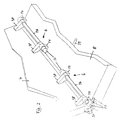
- Fig. 2 shows two redundant electrical actuators 12 which are connected to the Bearing blocks 14 of the panel 8 are fastened and on the shaft 16 of the joint 6 act.
- the shaft 16 is connected to the panel 4 by means of the lever 18, so that Panel 4 can be fully deployed, as shown in FIG. 6.
- the object of the invention is the integrated in the panels 4 and 8 heat pipes (heat pipes) 20 and 22 to be coupled using heat flow technology.
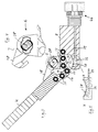
- the panel 8 has a recess or in the area of the heat pipes 22 Backdrop 24, while the panel 4 forms a nose or a projection 26, the contains the heat pipes 20.
- the backdrop 24 and the projection 26 are now dimensioned and with respect to the axis of rotation 28 of the joint 6 in their radii of curvature designed that the projection 26 slides into the scenery 24 with a slight play, without jamming or jamming.
- This 'game' now means that the Wall surfaces 30, 32 of the panels 4, 8 initially do not have sufficient contact, around a good areal thermal bridge between the heat pipes 20, 22 form.
- a pressure channel 36 In the wall 34 of the backdrop 24 is a pressure channel 36, the total or segmented can have a length of several meters and with a Membrane 38 - preferably made of metallic material - is closed.
- the Pressure channel 36 is by means of one or more pipes 39 with one or more Pressure sources 40 (e.g. spring-loaded bellows) connected.
- Pressure sources 40 e.g. spring-loaded bellows
- the pressure sources are activated forcibly or in a controlled manner, so that the membrane 38 the wall surface 30, 32 of the panels 4, 8 permanently and safely under the effect of the pressure from the pressure source 40 to a thermal bridge tense.
- the shaft 16 is not a solid body in cross section, but a segment and in the joint sleeve 40 has recesses 42 for the release of the joint.
- the thermal bridge is therefore free of counter forces.
- FIG. 7 to 9 show a further embodiment of the invention, wherein here the membrane 38 is concave and forms the wall 32 of the backdrop 24, while the projection 26 consists of three heat pipes 22 coupled to one another is formed.
- the membrane 38 is concave and forms the wall 32 of the backdrop 24, while the projection 26 consists of three heat pipes 22 coupled to one another is formed.
Landscapes
- Engineering & Computer Science (AREA)
- Life Sciences & Earth Sciences (AREA)
- Biodiversity & Conservation Biology (AREA)
- Environmental & Geological Engineering (AREA)
- Physics & Mathematics (AREA)
- Mechanical Engineering (AREA)
- General Engineering & Computer Science (AREA)
- Health & Medical Sciences (AREA)
- Sustainable Development (AREA)
- Thermal Sciences (AREA)
- Environmental Sciences (AREA)
- General Health & Medical Sciences (AREA)
- Toxicology (AREA)
- Remote Sensing (AREA)
- Aviation & Aerospace Engineering (AREA)
- Heat-Exchange Devices With Radiators And Conduit Assemblies (AREA)
- Tents Or Canopies (AREA)
- Supports For Pipes And Cables (AREA)
Abstract
Description
- Fig. 1:
- einen Satelliten mit ausgeklappten Radiator-Paneelen;
- Fig. 2:
- die Verbindung zweier Paneelen in axonometrischer Darstellung;
- Fig. 3:
- den Gegenstand von Fig. 2 in Schnittdarstellung;
- Fig. 4 und 5:
- Einzelheiten von Fig. 3 in vergrösserter Darstellung;
- Fig. 6:
- zwei Paneele in vollständig ausgeklapptem Zustand in Schnittdarstellung und
- Fig. 7, 8, 9:
- ein weiteres Ausführungsbeispiel der Erfindung in gefalteter, teilentfalteter und vollständig entfalteter Konfiguration
Claims (1)
- Wärmefluss-Kopplungs-Mechanismus zur Verwendung in der Raumfahrt, bestehend aus zwei Paneelen (4, 8), in die jeweils Wärmerohre (20, 22) integriert sind, wobeidas eine Paneel (8) eine Ausnehmung oder Kulisse (24) aufweist,das andere Paneel (4) eine der Kulisse angepasste Nase oder Vorsprung (26) aufweist,beide Paneele (4, 8) mittels mindestens eines Gelenks (6) miteinander verbunden sind,das Gelenk (6) radial freigegeben wird, wenn der Vorsprung (26) sich vollständig in der Kulisse (24) befindet unddurch gleichzeitige Freigabe einer Druckquelle (40) eine hydraulisch beaufschlagte Membran (38), die einen Druckkanal (36) abschliesst und einen Teil der Wand (34) der Kulisse (24) bildet, einen Anpressdruck liefert, der die beiden aneinanderliegenden Wandflächen (30, 32) der Paneele (4, 8) zu einer Wärmebrücke verspannt.
Applications Claiming Priority (2)
| Application Number | Priority Date | Filing Date | Title |
|---|---|---|---|
| DE19909167 | 1999-03-03 | ||
| DE1999109167 DE19909167A1 (de) | 1999-03-03 | 1999-03-03 | Wärmefluß-Koppelungs-Mechanismus zur Verwendung in der Raumfahrt |
Publications (2)
| Publication Number | Publication Date |
|---|---|
| EP1033302A2 true EP1033302A2 (de) | 2000-09-06 |
| EP1033302A3 EP1033302A3 (de) | 2001-04-25 |
Family
ID=7899474
Family Applications (1)
| Application Number | Title | Priority Date | Filing Date |
|---|---|---|---|
| EP00101416A Withdrawn EP1033302A3 (de) | 1999-03-03 | 2000-01-25 | Wärmefluss-Koppelungs-Mechanismus zur Verwendung in der Raumfahrt |
Country Status (2)
| Country | Link |
|---|---|
| EP (1) | EP1033302A3 (de) |
| DE (1) | DE19909167A1 (de) |
Cited By (1)
| Publication number | Priority date | Publication date | Assignee | Title |
|---|---|---|---|---|
| WO2026061654A1 (fr) | 2024-09-23 | 2026-03-26 | Airbus Defence And Space Sas | Système de jonction thermique entre deux éléments structurels mobiles en environnement spatial |
Family Cites Families (3)
| Publication number | Priority date | Publication date | Assignee | Title |
|---|---|---|---|---|
| US5344104A (en) * | 1992-09-21 | 1994-09-06 | General Electric Co. | Low cost, selectable configuration spacecraft |
| US5743325A (en) * | 1995-12-22 | 1998-04-28 | Hughes Electronics | Flexible heat transport design for deployable radiator applications |
| FR2761661A1 (fr) * | 1997-04-07 | 1998-10-09 | Aerospatiale | Systeme de transfert et de rejet de chaleur, notamment pour vehicules spatiaux |
-
1999
- 1999-03-03 DE DE1999109167 patent/DE19909167A1/de not_active Withdrawn
-
2000
- 2000-01-25 EP EP00101416A patent/EP1033302A3/de not_active Withdrawn
Non-Patent Citations (1)
| Title |
|---|
| None |
Cited By (1)
| Publication number | Priority date | Publication date | Assignee | Title |
|---|---|---|---|---|
| WO2026061654A1 (fr) | 2024-09-23 | 2026-03-26 | Airbus Defence And Space Sas | Système de jonction thermique entre deux éléments structurels mobiles en environnement spatial |
Also Published As
| Publication number | Publication date |
|---|---|
| DE19909167A1 (de) | 2000-09-07 |
| EP1033302A3 (de) | 2001-04-25 |
Similar Documents
| Publication | Publication Date | Title |
|---|---|---|
| DE602004005957T2 (de) | Vorrichtung zur Entfaltung und Steuerung der Steuerflächen eines Projektils | |
| EP3126245B1 (de) | Androgyne kopplungseinrichtung zur verbindung von modulen sowie entsprechende module | |
| DE1946086C3 (de) | Schaufel für Gasturbinenstrahltriebwerke | |
| DE2529543C2 (de) | Vorrichtung zur Betätigung der beweglichen Klappen von Schubdüsen | |
| DE2815573A1 (de) | Abgasduese mit veraenderlichem durchtrittsquerschnitt fuer gasturbinen und hebelgetriebeanordnung fuer eine solche abgasduese | |
| DE3331100A1 (de) | Stelleinrichtung fuer flugsteuerflaechen | |
| DE60107265T2 (de) | Raumfahrzeugadapter | |
| DE3510957A1 (de) | Redundanz-servoantrieb, insbesondere fuer die betaetigung von flugsteuerungsorganen in flugzeugen | |
| DE2260552A1 (de) | Stellfluegelanordnung fuer turbine | |
| EP0970330B1 (de) | Stufenventil, insbesondere kabinenabluftventil in einem fluggerät, und verfahren zur regulierung des kabinendrucks | |
| DE69001214T2 (de) | Abblasevorrichtung fuer ein mehrstrom-gasturbinentriebwerk. | |
| DE3444822A1 (de) | Regelbarer diffusor fuer einen lufteinlauf an einem flugzeug | |
| DE3242824A1 (de) | Schubduesenanordnung mit veraenderbarer querschnittsflaeche fuer ein gasturbinentriebwerk | |
| DE2819832C2 (de) | Bremsscheibenanordnung für Fahrzeug- Scheibenbremsen | |
| DE19818240A1 (de) | Reflektor und Reflektorelement für Antennen zum Einsatz im Weltraum, sowie Verfahren zum Entfalten eines Reflektors | |
| DE69725432T2 (de) | Befestigungsvorrichtung für eine divergierende Master-Düsenklappe einer Schubüse mit veränderlicher Geometrie | |
| DE69306267T2 (de) | Externer klappenvektormechanismus | |
| DE2349560B2 (de) | Schubdüse für ein Strahltriebwerk | |
| DE3242823A1 (de) | Schubduesenanordnung mit veraenderbarer querschnittsflaeche fuer ein gasturbinentriebwerk | |
| DE2542404A1 (de) | Kupplungsanordnung | |
| DE19909167A1 (de) | Wärmefluß-Koppelungs-Mechanismus zur Verwendung in der Raumfahrt | |
| DE102010031924A1 (de) | System zur Befestigung eines Luftfahrzeugsitzes | |
| DE2932423C3 (de) | Schirm | |
| DE60014783T2 (de) | Betätigungsvorrichtung für die schwenkbare schubdüse eines strahltriebwerks mit mehreren in umfangsrichtung verteilten elastischen bauteilen | |
| DE1525615C3 (de) | Haltevorrichtung für eine Manschettenanordnung |
Legal Events
| Date | Code | Title | Description |
|---|---|---|---|
| PUAI | Public reference made under article 153(3) epc to a published international application that has entered the european phase |
Free format text: ORIGINAL CODE: 0009012 |
|
| AK | Designated contracting states |
Kind code of ref document: A2 Designated state(s): BE DE FR GB IT |
|
| AX | Request for extension of the european patent |
Free format text: AL;LT;LV;MK;RO;SI |
|
| PUAL | Search report despatched |
Free format text: ORIGINAL CODE: 0009013 |
|
| AK | Designated contracting states |
Kind code of ref document: A3 Designated state(s): AT BE CH CY DE DK ES FI FR GB GR IE IT LI LU MC NL PT SE |
|
| AX | Request for extension of the european patent |
Free format text: AL;LT;LV;MK;RO;SI |
|
| RAP1 | Party data changed (applicant data changed or rights of an application transferred) |
Owner name: ASTRIUM GMBH |
|
| 17P | Request for examination filed |
Effective date: 20010517 |
|
| AKX | Designation fees paid |
Free format text: BE DE FR GB IT |
|
| GRAH | Despatch of communication of intention to grant a patent |
Free format text: ORIGINAL CODE: EPIDOS IGRA |
|
| STAA | Information on the status of an ep patent application or granted ep patent |
Free format text: STATUS: THE APPLICATION IS DEEMED TO BE WITHDRAWN |
|
| 18D | Application deemed to be withdrawn |
Effective date: 20030610 |