EP1031743A2 - Sicherungsvorrichtung für eine Schraube oder eine Schraubenmutter - Google Patents
Sicherungsvorrichtung für eine Schraube oder eine Schraubenmutter Download PDFInfo
- Publication number
- EP1031743A2 EP1031743A2 EP00103562A EP00103562A EP1031743A2 EP 1031743 A2 EP1031743 A2 EP 1031743A2 EP 00103562 A EP00103562 A EP 00103562A EP 00103562 A EP00103562 A EP 00103562A EP 1031743 A2 EP1031743 A2 EP 1031743A2
- Authority
- EP
- European Patent Office
- Prior art keywords
- screw
- nut
- receiving device
- receiving
- separation point
- Prior art date
- Legal status (The legal status is an assumption and is not a legal conclusion. Google has not performed a legal analysis and makes no representation as to the accuracy of the status listed.)
- Granted
Links
Images

Classifications
-
- F—MECHANICAL ENGINEERING; LIGHTING; HEATING; WEAPONS; BLASTING
- F16—ENGINEERING ELEMENTS AND UNITS; GENERAL MEASURES FOR PRODUCING AND MAINTAINING EFFECTIVE FUNCTIONING OF MACHINES OR INSTALLATIONS; THERMAL INSULATION IN GENERAL
- F16B—DEVICES FOR FASTENING OR SECURING CONSTRUCTIONAL ELEMENTS OR MACHINE PARTS TOGETHER, e.g. NAILS, BOLTS, CIRCLIPS, CLAMPS, CLIPS OR WEDGES; JOINTS OR JOINTING
- F16B39/00—Locking of screws, bolts or nuts
- F16B39/02—Locking of screws, bolts or nuts in which the locking takes place after screwing down
- F16B39/10—Locking of screws, bolts or nuts in which the locking takes place after screwing down by a plate, spring, wire or ring immovable with regard to the bolt or object and mainly perpendicular to the axis of the bolt
Definitions
- the invention relates to the field of fastening technology. It starts from one Securing device for a screw or a nut according to the preamble of the independent claim.
- the safety device according to the invention is disc-shaped and has one Holding device for receiving a screw or nut to be secured. Furthermore, the receiving device comprises at least one approach, the end of which, for example can be welded or glued to a component of a machine.
- This corresponding Approach advantageously has a separation point that is not in the range of rotation Screw nut or the screw head of the screw.
- By simply chiseling on The welded or glued end of the attachment can advantageously be used at this separation point almost contamination-free and very easy and quick from the rest of the approach disconnect and thus remove the safety device.
- the securing device has several approaches that are radial in the plane of the receiving device or arranged at any angle to the receiving device are. Such approaches enable the securing device to a component, in particular to a component of a machine that is difficult to access, by welding or gluing attach and fix the approaches. Using these embodiments of the approaches
- the safety device according to the invention it is possible to use screws or nuts in a flexible manner and according to any given spatial requirements secure and, if necessary, very easy to remove.
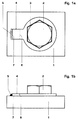
- FIG. 1a A top view of an exemplary embodiment of the securing device of a screw or nut is shown in FIG. 1a.
- the securing device is constructed in the form of a disk and comprises a receiving device 3 for receiving a screw head of a screw 2 or a screw nut.
- this receiving device 3 is provided with a hexagon socket and surrounds a screw head of a common hexagonal screw 2 flush.
- the securing device can thus be quickly and easily attached to the screw 2 or screw nut to be secured and a positive fit It is possible to secure screw 2 or the nut.
- the securing device has at least one attachment 4 on the receiving device 3, which is connected to the receiving device 3.
- the approach 4 ends with an approach end 7 that can be welded and / or glued.
- the securing device according to FIG. 1a is fixed to a component 1 via a welded or adhesive connection 5.
- the material of the attachment end 7 is to be matched to the base material of the component 1 so that welding and / or gluing becomes easier and cracking is avoided.
- the attachment end 7 is advantageously not in the range of rotation of the screw head of the screw 2 or the screw nut to be secured, since otherwise the screw head of the screw 2 or the screw nut would be damaged by fixing the securing device by means of welding and / or gluing.
- the approach 4 also includes a separation point 6, which can be separated by chisels.
- the separation point 6 can be separated by grinding, cutting or flame cutting.
- This separation point 6 is arranged on the neck 4 so that it is not in the range of rotation of the nut or the screw head of the screw 2. This ensures that the screw 2 to be secured or the screw nut is not damaged or destroyed when the glued and / or welded attachment end 7 is separated from the rest of the attachment 4, since rounding of the edges of the screw head of the screw 2 or the screw nut is prevented by turning .
- the separation point 6 is advantageously designed as a predetermined breaking point, so that the cutting through by chiseling at the separation point 6 can be carried out simply, quickly and almost without any contamination occurring.
- the securing device can advantageously also have a plurality of approaches, which are not all used to fix the securing device when the securing device is attached. This ensures that one and the same safety device can be used several times. In addition, trapezoidal, triangular, banana-shaped approaches are conceivable, which can be selected depending on the requirements of the component.
- FIG. 2. the securing device is designed with two lugs 4, each lug 4 being arranged at any angle to the receiving device 3.
- This embodiment of the securing device shown in FIG. 2 is particularly suitable for a component 1 in which the screw 2 or screw nut to be secured is arranged at a location that is difficult to access. Due to the arbitrary angle of the lugs 4 to the receiving device 3, it is therefore possible that the securing device can be flexibly adapted to the spatial requirements and thus the attachment and in particular the removal requires only very little effort. Further exemplary embodiments, not shown, are also conceivable, in which the receiving device 3 encloses a screw nut instead of a common screw 2.
- a receiving device which has an inner n-square for receiving an n-edged screw head or an n-edged screw nut, or a receiving device, not shown, which has an outer n-square for receiving, for example, a common internal square screw .
Landscapes
- Engineering & Computer Science (AREA)
- General Engineering & Computer Science (AREA)
- Mechanical Engineering (AREA)
- Bolts, Nuts, And Washers (AREA)
- Connection Of Plates (AREA)
- Mutual Connection Of Rods And Tubes (AREA)
- Transmission Devices (AREA)
Abstract
Description

- Fig. 1a
- ein Ausführungsbeispiel einer Sicherungsvorrichtung in der Draufsicht mit einem radial in der Ebene der Aufnahmeeinrichtung angeordneten Ansatz,
- Fig. 1b
- eine Darstellung des Ausführungsbeispiel der Sicherungsvorrichtung nach Fig.1a in der Vorderansicht,
- Fig. 2
- ein weiteres Ausführungsbeispiel einer Sicherungsvorrichtung in der Vorderansicht mit zwei in beliebigem Winkel zur Aufnahmeeinrichtung angeordneten Ansätzen.
Die Sicherungsvorrichtung weisst an der Aufnahmeeinrichtung 3 mindestens einen Ansatz 4 auf, der mit der Aufnahmeeinrichtung 3 verbunden ist. Der Ansatz 4 schliesst mit einem Ansatzende 7 ab, das verschweissbar und/oder verklebbar ist. Mittels dieses verschweissbaren oder verklebbaren Ansatzendes 7 ist die Sicherungsvorrichtung gemäss Fig. 1a über eine Schweiss- oder Klebeverbindung 5 an einem Bauteil 1 fixiert. Dabei ist das Material des Ansatzendes 7 auf das Grundmaterial des Bauteils 1 abzustimmen, damit das Schweissen und/oder Verkleben einfacher wird und eine Rissbildung vermieden wird. Das Ansatzende 7 liegt vorteilhafterweise nicht im Drehbereich des zu sichernden Schraubenkopfes der Schraube 2 oder der Schraubenmutter, da ansonsten der Schraubenkopf der Schraube 2 oder die Schraubenmutter durch die Fixierung der Sicherungsvorrichtung mittels Schweissen und/oder Verkleben beschädigt werden würde.
Der Ansatz 4 umfasst zudem eine Trennstelle 6, die durch Meisseln trennbar ist. Es ist aber auch durchaus denkbar, dass die Trennstelle 6 durch Schleifen, Trennschneiden oder Schneidbrennen getrennt werden kann. Diese Trennstelle 6 ist so am Ansatz 4 angeordnet, dass sie nicht im Drehbereich der Schraubenmutter oder des Schraubenkopfes der Schraube 2 liegt. Dadurch wird erreicht, dass die zu sichernde Schraube 2 oder die Schraubenmutter beim Trennen des verklebten und/oder verschweissten Ansatzendes 7 vom übrigen Ansatz 4 nicht beschädigt oder zerstört wird, da ein Abrunden der Kanten des Schraubenkopfes der Schraube 2 oder der Schraubenmutter durch Drehen verhindert wird. Vorteilhafterweise ist die Trennstelle 6 als Sollbruchstelle ausgestaltet, so dass das Durchtrennen durch Meisseln an der Trennstelle 6 einfach, zügig und nahezu ohne auftretende Verschmutzung vollzogen werden kann.
Der Ansatz 4 der Sicherungsvorrichtung gemäss Fig. 1 a ist radial in der Ebene der Aufnahmeeinrichtung 3 angeordnet. Eine solche Ausgestaltung des Ansatzes 4 ist besonders geeignet für eine Fixierung der Sicherungsvorrichtung an planen Flächen von Bauteilen durch Verschweissen oder Verkleben des Ansatzeendes 7 mit dem Bauteil 1, wie Fig. 1b in der Vorderansicht zeigt. Jedoch kann die Sicherungsvorrichtung vorteilhaft auch mehrere Ansätze aufweisen, die beim Anbringen der Sicherungsvorrichtung nicht alle zur Fixierung der Sicherungsvorrichtung genutzt werden. Dadurch wird erreicht, dass ein und dieselbe Sicherungsvorrichtung mehrmals eingesetzt werden kann. Zusätzlich sind trapezförmige, dreieckförmige, bananenförmige usw. Ansätze denkbar, die je nach Anforderungen an das Bauteil auszuwählen sind.
Ein weiteres Ausführungsbeispiel ist in Fig. 2 dargestellt. Darin ist die Sicherungsvorrichtung mit zwei Ansätzen 4 ausgeführt, wobei jeder Ansatz 4 in einem beliebigen Winkel zur Aufnahmeeinrichtung 3 angeordnet ist. Diese in Fig. 2 gezeigte Ausführungsform der Sicherungsvorrichtung eignet sich ganz besonders für ein Bauteil 1, bei dem die zu sichernde Schraube 2 oder Schraubenmutter an einer schwer zugänglichen Stelle angeordnet ist. Durch den beliebigen Winkel der Ansätze 4 zur Aufnahmeeinrichtung 3 ist es deshalb möglich, dass sich die Sicherungsvorrichtung in flexibler Weise den räumlichen Anforderungen anpassen lässt und somit das Anbringen und insbesondere das Entfernen nur einen sehr geringen Aufwand bedingt.
Weitere nicht dargestellte Ausführungsbeispiele sind ebenso denkbar, in denen die Aufnahmeeinrichtung 3 anstelle einer gängigen Schraube 2 eine Schraubenmutter umschliesst. Desweiteren ist eine nicht dargestellte Aufnahmeeinrichtung vorstellbar, die einen Innen-n-Kant zur Aufnahme eines n-kantigen Schraubenkopfes oder einer n-kantigen Schraubenmutter aufweist oder aber eine nicht dargestellte Aufnahmeeinrichtung, die einen Aussen-n-Kant zur Aufnahme beispielsweise einer gängigen Innenkantschraube aufweist.
- 1
- Bauteil
- 2
- Schraube
- 3
- Aufnahmeeinrichtung
- 4
- Ansatz
- 5
- Schweiss- oder Klebeverbindung
- 6
- Trennstelle
- 7
- Ansatzende
Claims (8)
- Sicherungsvorrichtung für eine Schraube oder Schraubenmutter, wobei die Sicherungsvorrichtung scheibenförmig ausgeführt und mit einer Aufnahmeeinrichtung (3) zur Aufnahme des Schraubenkopfes der Schraube (2) oder der Schraubenmutter versehen ist, dadurch gekennzeichnet,dass die Aufnahmeeinrichtung (3) mindestens einen Ansatz (4) mit einer Trennstelle (6) aufweist unddass die Trennstelle (6) nicht im Drehbereich des Schraubenkopfes der Schraube (2) oder der Schraubenmutter ist.
- Sicherungsvorrichtung nach Anspruch 1, dadurch gekennzeichnet, dass die Trennstelle (6) durch Meisseln, Trennschneiden, Schleifen oder Schneidbrennen trennbar ist.
- Sicherungsvorrichtung nach Anspruch 1 oder 2, dadurch gekennzeichnet, dass die Trennstelle (6) eine Sollbruchstelle umfasst.
- Sicherungsvorrichtung nach einem der Ansprüche 1 bis 3, dadurch gekennzeichnet, dass der Ansatz (4) ein Ansatzende (7) aufweist, das nicht im Drehbereich des Schraubenkopfes der Schraube (2) oder der Schraubenmutter ist.
- Sicherungsvorrichtung nach Anspruch 4, dadurch gekennzeichnet, dass der Ansatz (4) radial in der Ebene der Aufnahmeeinrichtung (3) angeordnet ist.
- Sicherungsvorrichtung nach Anspruch 4, dadurch gekennzeichnet, dass der Ansatz (4) in einem beliebigen Winkel zur Aufnahmeeinrichtung (3) angeordnet ist.
- Sicherungsvorrichtung nach einem der Ansprüche 1 bis 6, dadurch gekennzeichnet, dass das Ansatzende verklebbar und/oder verschweissbar ist.
- Sicherungsvorrichtung nach einem der Ansprüche 1 bis 7, dadurch gekennzeichnet, dass die Aufnahmeeinrichtung (3) einen Aussen-n-Kant oder einen Innen-n-Kant umfasst.
Applications Claiming Priority (2)
| Application Number | Priority Date | Filing Date | Title |
|---|---|---|---|
| DE19908134A DE19908134A1 (de) | 1999-02-25 | 1999-02-25 | Sicherungsvorrichtung für eine Schraube oder eine Schraubenmutter |
| DE19908134 | 1999-02-25 |
Publications (3)
| Publication Number | Publication Date |
|---|---|
| EP1031743A2 true EP1031743A2 (de) | 2000-08-30 |
| EP1031743A3 EP1031743A3 (de) | 2002-03-27 |
| EP1031743B1 EP1031743B1 (de) | 2005-10-26 |
Family
ID=7898822
Family Applications (1)
| Application Number | Title | Priority Date | Filing Date |
|---|---|---|---|
| EP00103562A Expired - Lifetime EP1031743B1 (de) | 1999-02-25 | 2000-02-19 | Sicherungsvorrichtung für eine Schraube oder eine Schraubenmutter |
Country Status (4)
| Country | Link |
|---|---|
| US (1) | US6241441B1 (de) |
| EP (1) | EP1031743B1 (de) |
| JP (1) | JP2000249130A (de) |
| DE (2) | DE19908134A1 (de) |
Cited By (2)
| Publication number | Priority date | Publication date | Assignee | Title |
|---|---|---|---|---|
| FR2952147A1 (fr) * | 2009-11-04 | 2011-05-06 | Air Liquide | Procede et un dispositif de blocage d'un ecrou de serrage d'une borne de distribution sur un reservoir de fluide |
| CN102720745A (zh) * | 2012-05-23 | 2012-10-10 | 河南省电力公司信阳供电公司 | 新型定位螺栓锁紧装置 |
Families Citing this family (12)
| Publication number | Priority date | Publication date | Assignee | Title |
|---|---|---|---|---|
| US6623624B2 (en) * | 2001-09-10 | 2003-09-23 | Chevron U.S.A. Inc. | Process for preparation of fuels and lubes in a single integrated hydrocracking system |
| US20040136806A1 (en) * | 2003-01-13 | 2004-07-15 | Montgomery Michael E. | Robust fastener locking device |
| JP4296903B2 (ja) * | 2003-11-13 | 2009-07-15 | コクヨ株式会社 | ナット保持装置及びナットホルダ |
| JP4017002B2 (ja) * | 2005-09-30 | 2007-12-05 | ダイキン工業株式会社 | 冷凍装置のケーシング構造及びそのケーシングの製造方法 |
| JP4881890B2 (ja) * | 2008-01-31 | 2012-02-22 | エムケー精工株式会社 | 基材におけるボルト保持構造 |
| CN201439793U (zh) * | 2009-03-07 | 2010-04-21 | 鸿富锦精密工业(深圳)有限公司 | 焊接螺母 |
| US20110271793A1 (en) * | 2009-05-19 | 2011-11-10 | Kenta Hatano | Cover and actuator |
| US8727684B1 (en) | 2013-02-04 | 2014-05-20 | General Electric Company | Nut retention device |
| EP2974883B1 (de) * | 2013-03-12 | 2023-07-12 | NTN Corporation | Radlagervorrichtung |
| US9309784B2 (en) | 2013-09-27 | 2016-04-12 | Siemens Energy, Inc. | Positioning arrangement having adjustable alignment constraint for low pressure stream turbine inner casing |
| JP6116755B2 (ja) * | 2014-03-27 | 2017-04-19 | 三菱電機株式会社 | エレベータ用ガイドレール固定装置およびその固定方法 |
| SE541741C2 (en) * | 2016-08-22 | 2019-12-03 | Scania Cv Ab | A locking plate unit comprising a locking plate and two adhered fasteners and a vehicle comprising such a locking plate unit |
Family Cites Families (10)
| Publication number | Priority date | Publication date | Assignee | Title |
|---|---|---|---|---|
| US818913A (en) * | 1903-10-30 | 1906-04-24 | Lewis Payne | Nut-lock. |
| US1358496A (en) * | 1920-03-26 | 1920-11-09 | Ernest C Austin | Nut-lock |
| US1498686A (en) * | 1922-03-20 | 1924-06-24 | William F Farnsworth | Keeper for nuts |
| US2472394A (en) * | 1947-09-17 | 1949-06-07 | Jacob A Barraket | Locking device |
| DE1720033A1 (de) * | 1966-03-02 | 1971-05-19 | Yoshitomi Pharmaceutical | Neue Indolderivate und Verfahren zu ihrer Herstellung |
| SE7501544L (sv) * | 1975-02-12 | 1976-08-16 | Asea Atom Ab | Lasbar mutteranordning |
| DE2903706A1 (de) * | 1979-01-31 | 1980-08-14 | Kraftwerk Union Ag | Verdrehsicherung fuer in ein bauteil eingeschraubte kopfschrauben |
| US4906150A (en) * | 1985-07-17 | 1990-03-06 | Bennett Bruce A | Locking fastener |
| DE19540743A1 (de) * | 1995-11-02 | 1997-05-07 | Asea Brown Boveri | Schraubensicherung |
| US6027293A (en) * | 1999-01-15 | 2000-02-22 | Deere & Company | Nut retaining plate |
-
1999
- 1999-02-25 DE DE19908134A patent/DE19908134A1/de not_active Withdrawn
-
2000
- 2000-02-19 DE DE50011407T patent/DE50011407D1/de not_active Expired - Lifetime
- 2000-02-19 EP EP00103562A patent/EP1031743B1/de not_active Expired - Lifetime
- 2000-02-22 US US09/510,356 patent/US6241441B1/en not_active Expired - Lifetime
- 2000-02-24 JP JP2000047857A patent/JP2000249130A/ja active Pending
Non-Patent Citations (1)
| Title |
|---|
| ROLOFF/MATEK: "machinenelemente", vol. 9, pages: S.193FF |
Cited By (3)
| Publication number | Priority date | Publication date | Assignee | Title |
|---|---|---|---|---|
| FR2952147A1 (fr) * | 2009-11-04 | 2011-05-06 | Air Liquide | Procede et un dispositif de blocage d'un ecrou de serrage d'une borne de distribution sur un reservoir de fluide |
| EP2320098A1 (de) * | 2009-11-04 | 2011-05-11 | L'Air Liquide Société Anonyme pour l'Etude et l'Exploitation des Procédés Georges Claude | Verfahren und Vorrichtung zur Arretierung einer Klemmmutter eines Versorgungselements auf einem Flüssigkeitsbehälter |
| CN102720745A (zh) * | 2012-05-23 | 2012-10-10 | 河南省电力公司信阳供电公司 | 新型定位螺栓锁紧装置 |
Also Published As
| Publication number | Publication date |
|---|---|
| EP1031743A3 (de) | 2002-03-27 |
| JP2000249130A (ja) | 2000-09-12 |
| DE50011407D1 (de) | 2005-12-01 |
| US6241441B1 (en) | 2001-06-05 |
| EP1031743B1 (de) | 2005-10-26 |
| DE19908134A1 (de) | 2000-08-31 |
Similar Documents
| Publication | Publication Date | Title |
|---|---|---|
| EP1031743A2 (de) | Sicherungsvorrichtung für eine Schraube oder eine Schraubenmutter | |
| DE4444496C2 (de) | Adapter zum Anschluß wechselbarer Werkzeuge an ein Arbeitsgerät | |
| DE10248866A1 (de) | Handwerkzeugmaschine | |
| EP1040972A2 (de) | Befestigungsanordnung für eine Einrichtung an einer Fahrzeugkarosserie | |
| EP2159003B1 (de) | Schutzhaube für ein rotierendes Objekt | |
| DE3903765A1 (de) | Schnellspanneinrichtung fuer scheibenfoermige bearbeitungswerkzeuge von elektrowerkzeugen | |
| DE2033556A1 (de) | Befestigungsanordnung | |
| DE29819955U1 (de) | Vorrichtung zum Verbinden zweier Platten | |
| EP0355344A1 (de) | Halterung für Pfosten | |
| DE2944833C2 (de) | Vorrichtung zur lösbaren Befestigung eines Stirnschleifringes | |
| DE102019111843A1 (de) | Zerspanungswerkzeug | |
| DE19533187C1 (de) | Fräswerkzeug zum Entfernen von auf Kfz-Kennzeichenschildern aufgeklebten Plaketten | |
| DE2827911A1 (de) | Diebstahlsicherung fuer kraftfahrzeug-kennzeichenschilder | |
| DE8816824U1 (de) | Schleifmaschine, insbesondere Feinschleifmaschine | |
| DE2943713C2 (de) | Halterung für Mischarme | |
| DE102004001580B3 (de) | Vorrichtung zum Verbinden eines Schleifwerkzeugs mit einer Werkzeugmaschine | |
| DE102014106658A1 (de) | Montagehilfe | |
| DE29912871U1 (de) | Verschraubungswerkzeug mit formschlüssigem Adapter | |
| EP1193025A2 (de) | Halterungsvorrichtung insbesondere zum Fixieren und/oder Lösen von Anbauteilen | |
| DE29510069U1 (de) | Schraubteil von einem Sicherheitsschließsystem | |
| DE102017127998A1 (de) | Lagergehäuse aus Blech | |
| DE9315706U1 (de) | Kabelverzweigerschrank | |
| DE29714001U1 (de) | Fräswerkzeug zum Entfernen von auf Oberflächen angebrachten Plaketten | |
| DE2826374A1 (de) | Betaetigungsvorrichtung fuer drehend arbeitende werkzeuge | |
| DE202015106009U1 (de) | Werkzeugkopf für eine Sanierfräsmaschine sowie Sanierfräsmaschine |
Legal Events
| Date | Code | Title | Description |
|---|---|---|---|
| PUAI | Public reference made under article 153(3) epc to a published international application that has entered the european phase |
Free format text: ORIGINAL CODE: 0009012 |
|
| AK | Designated contracting states |
Kind code of ref document: A2 Designated state(s): AT BE CH CY DE DK ES FI FR GB GR IE IT LI LU MC NL PT SE Kind code of ref document: A2 Designated state(s): CH DE FR GB IT LI SE |
|
| AX | Request for extension of the european patent |
Free format text: AL;LT;LV;MK;RO;SI |
|
| RAP1 | Party data changed (applicant data changed or rights of an application transferred) |
Owner name: ALSTOM |
|
| PUAL | Search report despatched |
Free format text: ORIGINAL CODE: 0009013 |
|
| AK | Designated contracting states |
Kind code of ref document: A3 Designated state(s): AT BE CH CY DE DK ES FI FR GB GR IE IT LI LU MC NL PT SE |
|
| AX | Request for extension of the european patent |
Free format text: AL;LT;LV;MK;RO;SI |
|
| 17P | Request for examination filed |
Effective date: 20020824 |
|
| RAP1 | Party data changed (applicant data changed or rights of an application transferred) |
Owner name: ALSTOM (SWITZERLAND) LTD |
|
| AKX | Designation fees paid |
Free format text: CH FR GB IT LI SE |
|
| RBV | Designated contracting states (corrected) |
Designated state(s): CH DE FR GB IT LI SE |
|
| 17Q | First examination report despatched |
Effective date: 20040216 |
|
| RAP1 | Party data changed (applicant data changed or rights of an application transferred) |
Owner name: ALSTOM TECHNOLOGY LTD |
|
| GRAP | Despatch of communication of intention to grant a patent |
Free format text: ORIGINAL CODE: EPIDOSNIGR1 |
|
| GRAS | Grant fee paid |
Free format text: ORIGINAL CODE: EPIDOSNIGR3 |
|
| GRAA | (expected) grant |
Free format text: ORIGINAL CODE: 0009210 |
|
| AK | Designated contracting states |
Kind code of ref document: B1 Designated state(s): CH DE FR GB IT LI SE |
|
| REG | Reference to a national code |
Ref country code: GB Ref legal event code: FG4D Free format text: NOT ENGLISH |
|
| REG | Reference to a national code |
Ref country code: CH Ref legal event code: EP |
|
| REF | Corresponds to: |
Ref document number: 50011407 Country of ref document: DE Date of ref document: 20051201 Kind code of ref document: P |
|
| REG | Reference to a national code |
Ref country code: CH Ref legal event code: NV Representative=s name: ALSTOM TECHNOLOGY LTD |
|
| GBT | Gb: translation of ep patent filed (gb section 77(6)(a)/1977) |
Effective date: 20051212 |
|
| REG | Reference to a national code |
Ref country code: SE Ref legal event code: TRGR |
|
| ET | Fr: translation filed | ||
| PLBE | No opposition filed within time limit |
Free format text: ORIGINAL CODE: 0009261 |
|
| STAA | Information on the status of an ep patent application or granted ep patent |
Free format text: STATUS: NO OPPOSITION FILED WITHIN TIME LIMIT |
|
| 26N | No opposition filed |
Effective date: 20060727 |
|
| REG | Reference to a national code |
Ref country code: FR Ref legal event code: PLFP Year of fee payment: 17 |
|
| REG | Reference to a national code |
Ref country code: CH Ref legal event code: PFA Owner name: GENERAL ELECTRIC TECHNOLOGY GMBH, CH Free format text: FORMER OWNER: ALSTOM TECHNOLOGY LTD, CH |
|
| REG | Reference to a national code |
Ref country code: DE Ref legal event code: R082 Ref document number: 50011407 Country of ref document: DE Representative=s name: RUEGER ABEL PATENTANWAELTE PARTGMBB, DE Ref country code: DE Ref legal event code: R082 Ref document number: 50011407 Country of ref document: DE Representative=s name: RUEGER, BARTHELT & ABEL, DE Ref country code: DE Ref legal event code: R082 Ref document number: 50011407 Country of ref document: DE Representative=s name: RUEGER ABEL PATENT- UND RECHTSANWAELTE, DE |
|
| REG | Reference to a national code |
Ref country code: DE Ref legal event code: R082 Ref document number: 50011407 Country of ref document: DE Representative=s name: RUEGER, BARTHELT & ABEL, DE Ref country code: DE Ref legal event code: R081 Ref document number: 50011407 Country of ref document: DE Owner name: GENERAL ELECTRIC TECHNOLOGY GMBH, CH Free format text: FORMER OWNER: ALSTOM TECHNOLOGY LTD., BADEN, CH Ref country code: DE Ref legal event code: R082 Ref document number: 50011407 Country of ref document: DE Representative=s name: RUEGER ABEL PATENT- UND RECHTSANWAELTE, DE |
|
| REG | Reference to a national code |
Ref country code: FR Ref legal event code: CD Owner name: ALSTOM TECHNOLOGY LTD, CH Effective date: 20161124 |
|
| REG | Reference to a national code |
Ref country code: FR Ref legal event code: PLFP Year of fee payment: 18 |
|
| PGFP | Annual fee paid to national office [announced via postgrant information from national office to epo] |
Ref country code: DE Payment date: 20170227 Year of fee payment: 18 Ref country code: FR Payment date: 20170223 Year of fee payment: 18 Ref country code: SE Payment date: 20170227 Year of fee payment: 18 Ref country code: CH Payment date: 20170227 Year of fee payment: 18 |
|
| PGFP | Annual fee paid to national office [announced via postgrant information from national office to epo] |
Ref country code: GB Payment date: 20170227 Year of fee payment: 18 |
|
| PGFP | Annual fee paid to national office [announced via postgrant information from national office to epo] |
Ref country code: IT Payment date: 20170223 Year of fee payment: 18 |
|
| REG | Reference to a national code |
Ref country code: DE Ref legal event code: R119 Ref document number: 50011407 Country of ref document: DE |
|
| REG | Reference to a national code |
Ref country code: CH Ref legal event code: PL |
|
| REG | Reference to a national code |
Ref country code: SE Ref legal event code: EUG |
|
| GBPC | Gb: european patent ceased through non-payment of renewal fee |
Effective date: 20180219 |
|
| PG25 | Lapsed in a contracting state [announced via postgrant information from national office to epo] |
Ref country code: SE Free format text: LAPSE BECAUSE OF NON-PAYMENT OF DUE FEES Effective date: 20180220 |
|
| PG25 | Lapsed in a contracting state [announced via postgrant information from national office to epo] |
Ref country code: CH Free format text: LAPSE BECAUSE OF NON-PAYMENT OF DUE FEES Effective date: 20180228 Ref country code: LI Free format text: LAPSE BECAUSE OF NON-PAYMENT OF DUE FEES Effective date: 20180228 |
|
| REG | Reference to a national code |
Ref country code: FR Ref legal event code: ST Effective date: 20181031 |
|
| PG25 | Lapsed in a contracting state [announced via postgrant information from national office to epo] |
Ref country code: DE Free format text: LAPSE BECAUSE OF NON-PAYMENT OF DUE FEES Effective date: 20180901 |
|
| PG25 | Lapsed in a contracting state [announced via postgrant information from national office to epo] |
Ref country code: IT Free format text: LAPSE BECAUSE OF NON-PAYMENT OF DUE FEES Effective date: 20180219 Ref country code: GB Free format text: LAPSE BECAUSE OF NON-PAYMENT OF DUE FEES Effective date: 20180219 Ref country code: FR Free format text: LAPSE BECAUSE OF NON-PAYMENT OF DUE FEES Effective date: 20180228 |