EP1031697B1 - Hydraulically actuated cover unit - Google Patents
Hydraulically actuated cover unit Download PDFInfo
- Publication number
- EP1031697B1 EP1031697B1 EP00200603A EP00200603A EP1031697B1 EP 1031697 B1 EP1031697 B1 EP 1031697B1 EP 00200603 A EP00200603 A EP 00200603A EP 00200603 A EP00200603 A EP 00200603A EP 1031697 B1 EP1031697 B1 EP 1031697B1
- Authority
- EP
- European Patent Office
- Prior art keywords
- mouth
- chamber
- bypass channel
- closing
- actuating device
- Prior art date
- Legal status (The legal status is an assumption and is not a legal conclusion. Google has not performed a legal analysis and makes no representation as to the accuracy of the status listed.)
- Expired - Lifetime
Links
Images


Classifications
-
- F—MECHANICAL ENGINEERING; LIGHTING; HEATING; WEAPONS; BLASTING
- F15—FLUID-PRESSURE ACTUATORS; HYDRAULICS OR PNEUMATICS IN GENERAL
- F15B—SYSTEMS ACTING BY MEANS OF FLUIDS IN GENERAL; FLUID-PRESSURE ACTUATORS, e.g. SERVOMOTORS; DETAILS OF FLUID-PRESSURE SYSTEMS, NOT OTHERWISE PROVIDED FOR
- F15B15/00—Fluid-actuated devices for displacing a member from one position to another; Gearing associated therewith
- F15B15/20—Other details, e.g. assembly with regulating devices
- F15B15/22—Other details, e.g. assembly with regulating devices for accelerating or decelerating the stroke
- F15B15/224—Other details, e.g. assembly with regulating devices for accelerating or decelerating the stroke having a piston which closes off fluid outlets in the cylinder bore by its own movement
-
- E—FIXED CONSTRUCTIONS
- E05—LOCKS; KEYS; WINDOW OR DOOR FITTINGS; SAFES
- E05F—DEVICES FOR MOVING WINGS INTO OPEN OR CLOSED POSITION; CHECKS FOR WINGS; WING FITTINGS NOT OTHERWISE PROVIDED FOR, CONCERNED WITH THE FUNCTIONING OF THE WING
- E05F15/00—Power-operated mechanisms for wings
- E05F15/40—Safety devices, e.g. detection of obstructions or end positions
- E05F15/49—Safety devices, e.g. detection of obstructions or end positions specially adapted for mechanisms operated by fluid pressure, e.g. detection by monitoring transmitted fluid pressure
-
- E—FIXED CONSTRUCTIONS
- E05—LOCKS; KEYS; WINDOW OR DOOR FITTINGS; SAFES
- E05F—DEVICES FOR MOVING WINGS INTO OPEN OR CLOSED POSITION; CHECKS FOR WINGS; WING FITTINGS NOT OTHERWISE PROVIDED FOR, CONCERNED WITH THE FUNCTIONING OF THE WING
- E05F15/00—Power-operated mechanisms for wings
- E05F15/50—Power-operated mechanisms for wings using fluid-pressure actuators
-
- E—FIXED CONSTRUCTIONS
- E05—LOCKS; KEYS; WINDOW OR DOOR FITTINGS; SAFES
- E05Y—INDEXING SCHEME RELATING TO HINGES OR OTHER SUSPENSION DEVICES FOR DOORS, WINDOWS OR WINGS AND DEVICES FOR MOVING WINGS INTO OPEN OR CLOSED POSITION, CHECKS FOR WINGS AND WING FITTINGS NOT OTHERWISE PROVIDED FOR, CONCERNED WITH THE FUNCTIONING OF THE WING
- E05Y2900/00—Application of doors, windows, wings or fittings thereof
- E05Y2900/50—Application of doors, windows, wings or fittings thereof for vehicles
- E05Y2900/53—Application of doors, windows, wings or fittings thereof for vehicles characterised by the type of wing
- E05Y2900/548—Trunk lids
-
- F—MECHANICAL ENGINEERING; LIGHTING; HEATING; WEAPONS; BLASTING
- F15—FLUID-PRESSURE ACTUATORS; HYDRAULICS OR PNEUMATICS IN GENERAL
- F15B—SYSTEMS ACTING BY MEANS OF FLUIDS IN GENERAL; FLUID-PRESSURE ACTUATORS, e.g. SERVOMOTORS; DETAILS OF FLUID-PRESSURE SYSTEMS, NOT OTHERWISE PROVIDED FOR
- F15B2211/00—Circuits for servomotor systems
- F15B2211/20—Fluid pressure source, e.g. accumulator or variable axial piston pump
- F15B2211/205—Systems with pumps
- F15B2211/2053—Type of pump
- F15B2211/20561—Type of pump reversible
Definitions
- the present invention relates to a hydraulic actuator for a cover for Covering an opening in a vehicle body, which Cover element is movable between its closed stand, in which the cover element covers the opening, and an open Stand in which the hydraulic actuator one double acting hydraulic actuator for moving the Cover element comprises, according to the preamble of claim 1.
- An actuator of this type is, for example, from known from DE-C-19 641 428.
- US 3,138,066 shows a double acting hydraulic actuator, wherein the movement of the piston / piston rod assembly near the respective end positions is damped. This damping takes place through a bypass channel provided by a check valve and several Outflow. The damping serves as speed control.
- DE 41 41 820 shows an adjustment device for a swivel part a vehicle.
- the adjustment device has one with a Motor drive and articulation system provided with the swivel part.
- the Motor drive can be hydraulically driven.
- the present invention is the Task based on a hydraulic actuator according to the Preamble of claim 1 to create that in a simple manner is executed and is extremely reliable.
- the measure according to claim 1 is the knowledge based on the fact that the actuator in such a way with the cover is connected, for example via suitable transmission means or directly that the speech is of a clear connection between the position of the piston / piston rod unit to the housing of the actuator on the one hand and the position of the cover element on the other hand.
- the piston / piston rod assembly then even serves as a switching element to during the desired moment the closing movement to open the first bypass channel and thus the to reduce power available from the actuator.
- the measure after the first aspect of the invention makes it possible to derive from the State of the art control of one or more electrically operated valves by means of control electronics, and the use of an additional position measuring device to Example in the form of the tilt angle sensor, what to do without leads to a price reduction. It is also important that the Protection against accidental pinching of an object between the closing cover and the body to Example of the trunk lid and the body of a vehicle, very much in the solution according to the first aspect of the invention reliable and not dependent on electronic parts.
- the Force available during the closing movement in two or actuator reduced by several levels. In its variation there is even more or less continuous reduction of the available actuator force possible.
- the actuator is a hydraulic actuator that is a whole with one associated electrically driven pump and a collection container for hydraulic fluid forms. In this version are no hydraulic hoses required at all.
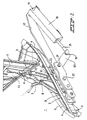
- FIG 1 part of the right rear is not another shown passenger car with trunk. How general known this part of the vehicle body includes a Luggage compartment opening 1, the body being along the Side, and mostly the top, of this trunk opening 1 extending and recessed gutter 2 forms.
- the Gutter has a gutter bottom wall 3 on one side of one Upright outer channel wall 4 is limited.
- the gutter wall 4 connects to an outside of the gutter 2 and higher Exterior wall of the vehicle body, which wall is not shown here is.
- the channel bottom 3 is from one Upright inner channel wall 5, which is limited to one flexible sealing strips extending along its top (not shown) is provided.
- the vehicle also has one Trunk lid 6 for closing the opening 1 of the trunk.
- the trunk lid 6 is about a hinge means in essential horizontal joint axis line articulated on the Vehicle body attached and is movable between its closed stand, in which the trunk lid 6 on the Sealing strip rests on the inner channel wall 5 (so that the Trunk is sealed from the outside atmosphere) and one around an angle to the closed stand upright open Stand (which is shown in Figure 1).
- the hinge means in this example include on each side of the Trunk lid 6 two rods 7, 8, each on their one End via an associated hinge point, or 9, 10 with the vehicle body and at its other end over one associated hinge point, or 11, 12 with one at the Bottom of the trunk lid 6 arranged support 13 articulated are connected.
- these form two Rods 7, 8 with their associated hinge points a so-called Four-bar linkage structure.
- the rods 7, 8 are set up and designed in such a way that these rods in the closed position of the trunk lid 6 lie in the gutter 2.
- the gutter 2 is from above of the part of the Trunk lid 6 covered, but even then the gutter is 2 still in connection with the outside atmosphere.
- the vehicle is for opening and closing the trunk opening 1 further provided with an actuator that here is carried out electrohydraulically.
- the electrohydraulic Actuating device includes one not shown electrically driven pump and a collection container for hydraulic fluid a double acting hydraulic Drive cylinder 30 between the vehicle body and the Trunk lid set up to move the trunk lid 6 is.
- the cylinder 30 has a cylinder housing 31 on the bottom side articulated, connected to a support structure 17 by means of pins 16 which is in turn on the inside of the body on the upright gutter wall 4 is attached.
- the cylinder 30 has a reciprocating piston rod 35, via a ball joint coupling 19 with the end of a lever 20 connected is.
- the lever 20 is fixed to one Axis 21 connected, which extends transversely to the lever 20.
- the Axle 21 is at one end through an additional support 22 and sticks in the other direction through the support 17 and then through an opening 23 provided with a sealing ring in the channel wall 4 to the gutter 2.
- the part protruding into the gutter 2 the axis 21 forms the hinge point 10 of the rod 8 and is fixed connected to this rod 8.
- FIG Vehicle body For the sake of clarity, the illustration in FIG Vehicle body omitted. Another is from FIG additional support 24 can be seen in the gutter 2 on the Channel wall 4 is arranged and a solid base for the Points of articulation of the rods 7, 8 creates.
- the support 17 on which the cylinder 30 is supported also forms a Rotary bearing for the axis 21, so that from the cylinder 30 to the Axis 21 applied force is absorbed by the support 17 and does not affect the body.
- the drive cylinder 30 is located in one of the Vehicle body shielded space, instead of in the gutter 2.
- the cylinder 30 and any associated Hoses not resistant to direct exposure To be weather influences, and the weather influences have too less effect on the effect of the hydraulic Actuator.
- Through one of the poles of the itself known four-bar linkage mechanism as part of the transmission between cylinder 15 and the trunk lid to use additional costs will be saved and will also be one of Obtaining an appealing solution. In fact, from the outside are hardly noticed in what way the trunk lid 6th is moved.
- the implementation can be well sealed because water is displaced all over the channel bottom 3 becomes. Furthermore, this list means that there are few problems with the Piles of dirt occur when the transfer medium is in a distance above the channel bottom 3.
- the cylinder 30 is as follows based on the other figures will be explained.
- trunk lid which is here will be almost horizontal in the closed stand, too be applicable to a so-called fifth door of a motor vehicle which fifth door is often almost in its closed position stands vertically.
- present Invention for example also applicable to the car doors and the Hood of a motor vehicle can be. by name Trucks have articulated around a horizontal axis Bonnets with a heavy weight.
- the invention is also applicable when the cover member Folding hood or the like is.
- cover member Folding hood or the like is.
- FIG. 3 shows the double-acting hydraulic cylinder 30 shown.
- the cylinder 30 has a housing 31 with a cylinder space 32, in which a piston 33 with a on the cylindrical wall of the Cylinder chamber 32 sealing ring 34 axially back and forth is mobile.
- a piston rod 35 is fixed to the piston 33 fastened and protrudes through a seal 36 from the housing 31 out.
- the piston / piston rod unit is between the inserted End position and the extended end position movable back and forth.
- the piston 33 distributes the cylinder space 32 into a first chamber 38 and a second chamber 39, each one of the prior art
- the piston / piston rod unit have a dependent volume.
- the housing 31 has one communicating with the chamber 38 Port 40 and a port 41 with the chamber 39 in Connection is established so that hydraulic connections 40, 41 Liquid can be supplied and removed.
- the first chamber 38 is the closing chamber because when hydraulic fluid is supplied to it, the cylinder 30 can deliver a force that leads to the closing movement of the Trunk lid 6 leads.
- the chamber 39 is then the Opening chamber of the cylinder 30.
- the length of this first part is determined by the location of the Cylinder chamber 32 adjoining mouth 42 of a first bypass channel certainly. This mouth 42 is located in the housing Cross bore 43 has been formed.
- the transverse bore 43 is stepped executed so that a seat for the ball 44 is obtained, the is pressed towards the seat by means of the spring 45. This results in a closing in the direction of the cylinder space Check valve in the first bypass channel.
- the transverse bore 47 is on the outside of the housing 31 by means of a plug completed.
- a transverse bore 50 connects the transverse bores 43 and 47 with each other and with the connection 41, so that both bypass channels with the terminal 41 are connected.
- the passage of the part of the transverse bore 43 between the ball 44 and the mouth 42 is smaller than the passage of the part of the Cross bore 47 between the ball 48 and the mouth 46 so that the effective passage of the second bypass channel is smaller than that of first bypass channel.
- the passage of the mouth 42 is significantly smaller than that of the port 40 of the chamber 38, while the passage of the Mouth 46 is almost the same size as that of the connector 40.
- the mouths 42 and 46 between them a second part of the axial Displacement range of the piston / piston rod unit. If at Pushing out the piston rod, the sealing ring 34 passes through the mouth 42 hydraulic fluid can flow out through the first bypass channel the first chamber 38, via the mouth 42 along that of its seat pressed ball 44 and through the transverse bore 50 to the second chamber belonging port 41, and from there to the Collection container of the hydraulic system, not shown stream.
- the area between the mouth 46 and the mouth of the terminal 41 defines a third part of the axial displacement range of the piston / piston rod unit.
- the mouth 46 can be via the mouth 46 of the second bypass channel, along the 48 hydraulic ball pressed from its seat Liquid to the connection 41 belonging to the second chamber 39 and flow from there to the collection container.
- the springs 45 and 49 can be light return springs, whereby the associated balls are pressed directly from their seat when when pushing out the piston rod, the piston such a stand assumes that the associated mouth of the bypass channel is opened.
- the Springs 45 and 49 are designed in such a way that the associated balls can only move from their seat when in the closing chamber 38 exceeds a predetermined pressure level is. This then prevents that already at one low hydraulic pressure in the chamber 38 hydraulic Liquid flows out of the chamber via the bypass channel.
- Figure 4 shows an example of a hydraulic system in which the Cylinder 30 for the application shown in Figures 1 and 2 is arranged.
- FIG 4 is a reversible pump 51 with a suction / Outflow connection 52 and a suction / outflow connection 53 shown. Both connections 52, 53 are in a suction change valve 54 in Connection with a collecting tank 55 for hydraulic Liquid. Pressure relief valves 56 and 57 are also provided Limitation of the maximum hydraulic pressure in the system intended.
- the connections 52 and 53 are respectively to the connections 40 and 41 of the cylinder 30 connected, each in Connection line one of hydraulic fluid flow actuatable valve, or 57 and 58, is arranged.
- These valves 57, 58 are known per se and each include a sliding body that moves back and forth in a hole a central passage channel that is restricted is.
- a connection to the hole then connects each time Collection container 55 on and further a return spring is provided.
- a flow of hydraulic fluid from an outflow connection of the pump to the associated connection pushes the sliding body against the force of the light spring and covers the connection to the container 55.
- one current or in a current in opposite Direction is the connection to the reservoir 55 of this valve 57, 58 just open.
- the cylinder 30 is particularly suitable because of the supply hydraulic fluid to the chamber 38 a closing movement of the Trunk lid 6 with a gradually decreasing from that Cylinder 30 deliverable force is realized.
- the cylinder 30 also delivers a high level in this application Security, as the jamming of an object in the third and possibly second part of the axial runout of the Piston / piston rod unit will play.
- a bypass channel is always open so that the chamber 38 supplied hydraulic fluid can flow out and none undesirably large force can be supplied by the cylinder 30.
- the fuse is not from a valve or other fault-sensitive part.
- this part of the cylinder space could be used a larger diameter, so that hydraulic Pass liquid between the piston and the cylinder wall can.
- Fig. 5 shows a double-acting hydraulic cylinder 60, the effect explained with reference to FIG 3 in a constructively different has been realized wisely.
- the cylinder 60 has a housing 61 with a cylinder space 62 and a back and forth in this displaceable piston 63, which is a first in the cylinder chamber 62 Chamber 65 and a second chamber 66 forms. There is also a connection 67 to the first chamber 65 and a connection to the second chamber 66 seen.
- the piston 63 is provided with a first sealing ring 70, which is designed to seal on the cylindrical wall of the cylinder space 62 to lie on.
- a second sealing ring 71 is also provided, the effect of which will be explained below.
- the sealing ring 70 seals on the wall of the cylinder space 62.
- shallow grooves 72 that extend over a central region of the cylinder space 62 extend, define one adjoining the first part second part of the displacement range of the piston 63.
- the sealing ring 70 seals the shallow grooves 72 not from, so that 72 hydraulic fluid from these grooves the chamber 65 can flow to the chamber 66.
- the seal is 71 such a design that it is capable of the grooves 72 seal, but this acts like a kind of check valve, which in Direction towards chamber 66 to chamber 65 and in in the opposite direction allows the liquid to pass. This is possible, for example, that the sealing ring 71 with a flexible annular lip protruding from the piston is executed.
- the sealing ring 70 seals the Not grooves 73, so that the hydraulic 73 on these grooves Liquid can easily flow from chamber 65 to chamber 66.
- the seal 71 is such a design that it is is able to seal the grooves 73, but this works also like a kind of check valve that closes in the direction to chamber 66 to chamber 65 and the liquid into the other direction.
- Cylinder 60 may suitably be in place of cylinder 30 in Figure 1 can be used, with hydraulic when feeding Liquid to the chamber 65 of the trunk lid 6 a Closing movement executes.
- the grooves 72 which are a kind hydraulic restriction, can automatically when extended realized a reduction in the force available from the cylinder become.
- the piston 63 reaches the deeper grooves 73, the possibly further force to be supplied by the cylinder 60 after, almost to zero. This ensures that the Trunk lid 6 quietly comes on the body and at the same time becomes a safeguard against the use of an impermissibly large force an obstacle that may be in the path of the closing Trunk lid is created.
- Figure 6 shows a modification of the cylinder 30 of Figure 3.
- the in 6 cylinder 80 shown has a housing 81 with a Cylinder chamber 82 and a piston movable back and forth in this 83, a first chamber 85 and a second one in the cylinder chamber 82 Chamber 86 forms. There is also a connection 87 to the first chamber 85 and a connection to the second chamber 86 can be seen.
- the piston 83 is provided with a sealing ring 90 for this purpose is designed to seal on the cylindrical wall of the cylinder space 82 to lie on. Furthermore, two mouths 91 and 92 can be seen, the are connected to terminal 87. This is very similar with the execution of Figure 3, but this is because different that the mouths 91, 92 with the other connection of the Cylinder 80 are connected. For a closing application of a cover, as in FIGS. 1 and 2, this cylinder 80 be set up in such a way that the closing with the incoming stroke of the piston 83 matches. Then it will hydraulic fluid is supplied to the connection 88. Mouths 91, 92 then effect the two-stage reduction in the deliverable Force.
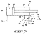
- the double-acting cylinder 100 is shown, which for Example can be applied at the location of the cylinder 30.
- the Cylinder 100 has a housing 101 with a cylinder space in which a Piston 102 one on the cylindrical wall of the cylinder space sealing ring is axially movable back and forth.
- a Piston rod 103 is fixedly attached to the piston 102 and protrudes by a seal out of the housing 101.
- the piston / piston rod unit is between the inserted End position and the extended end position movable back and forth.
- the piston 102 distributes the cylinder space into a first chamber 104 and a second chamber 105, each one of the prior art
- the piston / piston rod unit have a dependent volume.
- Housing 101 has one in communication with chamber 104 standing connection 106 and a connection 107, with the chamber 105 is connected, so that via the connections 106, 107 hydraulic fluid can be supplied and discharged.
- the cylinder 30 In the Application at the location of the cylinder 30 would be the first chamber 104 the lock chamber be there if it's hydraulic fluid is supplied, the cylinder 30 can deliver a force that is used to Closing movement of the trunk lid 6 leads. Chamber 105 is then the opening chamber of the cylinder.
- the length of this first part is determined by the location of the Mouth 108 of a bypass channel 109 adjoining the cylinder space.
- the bypass channel 109 is one in the direction of the Check valve 115 closing cylinder chamber is added.
- the opening port 107 closes over a channel 110 at one Mouth 111 to camera 105.
- a throttle 112 is located in the channel 110 added.
- the bypass channel 109 connects to the channel 110 between the Throttle 112 and the connection 107.
- a circulation channel 113 is provided around throttle 112 around.
- Channel 113 closes on both sides of the choke 112 on the channel 110.
- In channel 113 is an in Check valve 114 closing on port 107 added.
- the cylinder 100 can be advantageously used for driving from a folding top of a passenger car, the Ejecting movement of the piston rod 103 corresponds to that Closing movement of the folding top. Velocity damping prevents the folding top from being too hard on the window post the windshield comes up.
- the solution shown in Figure 7 can also on the other side of the cylinder 100 can be provided.
- this second cylinder can be a standard cylinder without Bypass channels because this second cylinder is then the bypass channels can use in the first cylinder.
Abstract
Description
Die vorliegende Erfindung Betrifft
eine hydraulische Betätigungsvorrichtung für ein Abdeckelement zum
Abdecken einer Öffnung in einer Fahrzeugkarosserie, welches
Abdeckelement beweglich ist zwischen seinem geschlossenen Stand, in
dem das Abdeckelement die Öffnung abdeckt, und einem geöffneten
Stand, bei dem die hydraulische Betätigungsvorrichtung einen
doppeltwirkenden hydraulischen Aktuator zum Bewegen des
Abdeckelements umfaßt, gemäß dem Oberbegriff des Patentanspruchs 1.
Eine Betätigungsvorrichtung dieser Art ist beispielsweise aus
der DE-C-19 641 428 bekannt.The present invention relates to
a hydraulic actuator for a cover for
Covering an opening in a vehicle body, which
Cover element is movable between its closed stand, in
which the cover element covers the opening, and an open
Stand in which the hydraulic actuator one
double acting hydraulic actuator for moving the
Cover element comprises, according to the preamble of
Bei einem derartigen Antrieb ist es erwünscht, daß die von dem hydraulischen Aktuator lieferbare Antriebskraft während der Schließbewegung des Abdeckelements nachläßt. Insbesondere ist es oft erwünscht, daß die lieferbare Antriebskraft nahe der geschlossenen Lage des Abdeckelements gering, oder aber gleich Null ist. Dies zum Vorbeugen eines mit unerwünscht großer Geschwindigkeit und Kraft Erreichens des Schließstandes und/oder aus Sicherheitsgründen, wobei es sich vor allem um jene Situation handelt, in der sich ein Objekt, zum Beispiel ein Körperteil oder ein aus dem Kofferraum herausragendes Gepäckstück, in der Bahn des schließenden Abdeckelements befindet.With such a drive, it is desirable that the hydraulic actuator available driving force during the Closing movement of the cover element subsides. In particular it is often desired that the deliverable driving force be close to that closed position of the cover element low, or zero is. This is to prevent an undesirably large one Speed and force reaching the closing position and / or for security reasons, which is primarily that situation in which there is an object, for example a body part or a piece of luggage protruding from the trunk, in the path of the closing cover element is located.
Um zu bewirken, daß das Abdeckelement trotz der Reduzierung der Aktuatorkraft dennoch zuverlässig die geschlossene Lage erreicht, können zusätzliche Mittel vorgesehen sein, zum Beispiel eine Feder, aber es ist auch möglich, die Geschwindigkeit, die das Abdeckelement erreicht hat und/oder die Schwerkraft, selbstverständlich abhängig von der Aufstellung des Abdeckelements, zu benutzen.In order to cause the cover element despite the reduction in Actuator force nevertheless reliably reaches the closed position, additional means can be provided, for example a spring, but it is also possible the speed that that Has reached cover element and / or gravity, of course depending on the installation of the cover element, to use.
Aus der DE 44 07 739 ist eine hydraulische Antriebseinrichtung eines Faltverdecks eines Cabrioletfahrzeugs bekannt, in der Maßnahmen getroffen sind, um zu verhindern, daß beim Schließen des Faltverdecks sein vorderer Rand zu hart auf den Fensterpfosten über der Windschutzscheibe aufkommt. Dazu ist bei dieser bekannten Abdeckeinheit vorgesehen, daß beim Schließen des Faltverdecks zuerst nur die Schließkammern der zugehörigen hydraulischen Antriebszylinder unter hydraulischen Druck gesetzt werden, während die Öffnungskammern jener Zylinder mit dem Sammelbehälter verbunden sind. Nahe der geschlossenen Lage des Faltverdecks wird dann durch eine geeignete Ansteuerung der zu diesen Abtriebszylindern gehörenden Ventile bewirkt, daß auch die Öffnungskammer dieser Zylinder unter hydraulischen Druck gesetzt werden. Dies ist auch als das differential oder regenerativ Betreiben dieser Zylinder bekannt, wodurch die von diesen Zylindern lieferbare Kraft verringert wird.From DE 44 07 739 is a hydraulic drive device a folding top of a convertible vehicle known in the Measures are taken to prevent the closing of the Folding top over its hard edge on the window post the windshield comes up. This is known in this Cover unit provided that when closing the folding top first only the locking chambers of the associated hydraulic Drive cylinders are pressurized while the opening chambers of those cylinders are connected to the collection container are. Then close to the closed position of the folding top a suitable control of these output cylinders belonging valves also causes the opening chamber of this Cylinders are put under hydraulic pressure. It is also as the differential or regenerative operation of these cylinders known, whereby the force available from these cylinders is reduced.
In der Druckschrift DE 196 41 428,
die dem Oberbegriff des Anspruchs 1 zugrunde liegt,
sowie in der EP 0 803 630, ist ein
hydraulischer Antrieb für einen Kofferraumdeckel eines
Kraftfahrzeugs beschrieben, wobei die Schließbewegung, aus der
geöffneten Lage gesehen, einen ersten, zweiten und dritten
Winkelbereich aufweist. Hierbei ist der hydraulische Antrieb so
ausgeführt, daß die von den Antriebszylindern lieferbare Kraft in
dem zweiten Winkelbereich geringer ist als in dem ersten
Winkelbereich. Dies wird mittels einer zusätzlichen
Verbindungsleitung und eines in dieser angeordneten elektrischen
betätigbaren Ventils realisiert, mit dem in dem zweiten
Winkelbereich die Förderstrom der Pumpe zum größten Teil direkt in
den Sammelbehälter zurückgeführt wird. Hierdurch ist der Druck in
der Schließkammer des Zylinders in dem zweiten Winkelbereich viel
geringer als in dem ersten Winkelbereich. In dem dritten
Winkelbereich wird die Hydraulikpumpe ausgeschaltet, so daß der
Druck in den Zylindern bis auf Null nachläßt und der
Kofferraumdeckel sich nur unter Einfluß seines Gewichts weiter
fortbewegt.In the publication DE 196 41 428,
on which the preamble of
In der DE 44 07 739 wird angenommen, daß es ausreichend ist,
mittels eines Zeitschalters zu bestimmen, an welchem Zeitpunkt die
Ventile angesteuert werden müssen, um die Zylinder differential zu
betreiben zu können, aber dabei wird nicht mit einem eventuell
abweichenden Ablauf der Schließbewegung gerechnet. Eine solche
Abweichung kann zum Beispiel aus einer vom normalen abweichenden
Umgebungstemperatur hervorgehen, oder dadurch, daß das
Abdeckelement zeitweilig zurückgehalten wurde. Auch können
Abweichungen infolge des Wechsels Schließen/Öffnen/Schließen
entstehen. In der DE 196 41 428 hat man dieses Problem dadurch
gelöst, daß ein Neigungswinkelsensor an dem Kofferraumdeckel
angeordnet wurde. Dies ist aber eine kostspielige Lösung, die
übrigens nicht zuverlässig funktioniert, wenn das Fahrzeug selbst
unter einem Winkel steht, zum Beipiel auf einem Gefälle. In diesem
Fall würde ein zweiter Neigungswinkelsensor erforderlich sein, um
den Stand des Fahrzeugs selbst festzustellen. Auch wird ein
Verbindungsdraht zwischen dem Sensor und der Steuerungselektronik
des Antriebssystems erforderlich sein, welcher Draht beim Übergang
vom Kofferraumdeckel zur Karosserie leicht beschädigt werden kann.
US 3.138.066 zeigt eine doppeltwirkende hydraulische Aktuator, wobei die Bewegung von der Kolben/Kolbenstangeneinheit in der Nähe von den jeweiligen Endlagen gedämpft wird. Diese Dämpfung findet statt durch ein von einem Rückschlagventil versehenes Bypass-Kanal und mehrere Ausströmöffnungen. Die Dämpfung dient als Geschwindigkeitsregelung.US 3,138,066 shows a double acting hydraulic actuator, wherein the movement of the piston / piston rod assembly near the respective end positions is damped. This damping takes place through a bypass channel provided by a check valve and several Outflow. The damping serves as speed control.
DE 41 41 820 zeigt eine Verstellvorrichtung für ein Schwenkteil an einem Fahrzeug. Die Verstellvorrichtung hat ein mit einem Motorantrieb und den Schwenkteil versehenes Gelenksystem. Der Motorantrieb kann hydraulisch angetrieben sein.DE 41 41 820 shows an adjustment device for a swivel part a vehicle. The adjustment device has one with a Motor drive and articulation system provided with the swivel part. The Motor drive can be hydraulically driven.
Der vorliegenden Erfindung liegt die
Aufgabe zugrunde, eine hydraulische Betätigungsvorrichtung nach dem
Oberbegriff des Anspruchs 1 zu schaffen, die in einfacher Weise
ausgeführt ist und äußerst zuverlässig ist.The present invention is the
Task based on a hydraulic actuator according to the
Preamble of
Diese Aufgabe wird gemäß der Erfindung durch die hydraulische Betätigungseinrichtung
nach Anspruch 1 gelöst.This object is achieved according to the invention by the hydraulic actuator
solved according to
Vorteilhafte Weiterbildungen der Erfindung sind Gegenstand der abhängigen Ansprüche.Advantageous developments of the invention are the subject of the dependent claims.
Der Maßnahme nach Anspruch 1 liegt die Erkenntnis
zugrunde, daß der Aktuator in solcher Weise mit dem Abdeckelement
verbunden ist, zum Beispiel über geeignete Übertragungsmittel oder
direkt, daß die Rede ist von einem eindeutigen Zusammenhang
zwischen dem Stand der Kolben/Kolbenstangeneinheit zu dem Gehäuse
des Aktuators einerseits und der Lage des Abdeckelements
anderseits. Dies bedeutet, daß die Kolben/Kolbenstangeneinheit dann
selbst als Schaltelement dient, um am gewünschten Moment während
der Schließbewegung den ersten Bypass-Kanal zu öffnen und damit die
von dem Aktuator lieferbare Kraft zu verringern. Die Maßnahme nach
dem ersten Aspekt der Erfindung ermöglicht es, auf die aus dem
Stand der Technik bekannte Ansteuerung eines oder mehrerer
elektrischer betätigbarer Ventile mittels Steuerungselektronik,
sowie die Anwendung eines zusätzlichen Positionsmeßgeräts, zum
Beispiel in der Form des Neigungswinkelsensors, zu verzichten, was
zu einer Kostpreissenkung führt. Weiter ist es wichtig, daß die
Sicherung gegen ein unbeabsichtigtes Einklemmen eines Objekts
zwischen dem schließenden Abdeckelement und dem Körper, zum
Beispiel dem Kofferraumdeckel und der Karosserie eines Fahrzeugs,
bei der Lösung nach dem ersten Aspekt der Erfindung sehr
zuverlässig und nicht abhängig von elektronischen Teilen ist. The measure according to
In einer bevorzugten Ausbildung wird die von dem Aktuator lieferbare Kraft während der Schließbewegung in zwei oder mehreren Stufen reduziert. In deren Abwandlung ist sogar eine mehr oder weniger stufenlose Reduzierung der lieferbaren Aktuatorkraft möglich.In a preferred embodiment, the Force available during the closing movement in two or actuator reduced by several levels. In its variation there is even more or less continuous reduction of the available actuator force possible.
In einer weiteren bevorzugten Ausbildung ist vorgesehen, daß der Aktuator ein hydraulischer Aktuator ist, der ein Ganzes mit einer zugehörigen elektrisch antreibbaren Pumpe und einem Sammelbehälter fur hydraulische Flüssigkeit bildet. Bei dieser Ausführung sind überhaupt keine hydraulischen Schläuche erforderlich.In a further preferred embodiment it is provided that the actuator is a hydraulic actuator that is a whole with one associated electrically driven pump and a collection container for hydraulic fluid forms. In this version are no hydraulic hoses required at all.
Weitere vorteilhafte Ausbildungen der Erfindung werden nachfolgend anhand der Zeichnung und der Ansprüche erläutert werden. Es zeigt:
- Fig. 1
- perpektivisch einen Teil eines Fahrzeugs nach der vorliegenden Erfindung,
- Fig. 2
- perspektivisch in entgegengesetzter Richtung der
Figur 1 die hydraulische Betätigungsvorrichtung derFigur 1, - Fig. 3
- eine bevorzugte Ausbildung eines erfindungsgemäßen hydraulischen Zylinders im Längsschnitt,
- Fig. 4
- ein hydraulisches Schema mit dem Zylinder nach
Figur 3, - Fig. 5
- eine andere Ausbildung eines erfindungsgemäßen hydraulischen Antriebszylinders im Längsschnitt,
- Fig. 6
- eine weitere Ausbildung eines erfindungsgemäßen hydraulischen Antriebszylinders im Längsschnitt.
- Fig. 7
- abermals eine weitere Ausbildung eines erfindungsgemäßen hydraulischen Antriebszylinders im Längsschnitt.
- Fig. 1
- perspective part of a vehicle according to the present invention,
- Fig. 2
- perspective in the opposite direction of Figure 1, the hydraulic actuator of Figure 1,
- Fig. 3
- a preferred embodiment of a hydraulic cylinder according to the invention in longitudinal section,
- Fig. 4
- 4 shows a hydraulic diagram with the cylinder according to FIG. 3,
- Fig. 5
- another embodiment of a hydraulic drive cylinder according to the invention in longitudinal section,
- Fig. 6
- a further embodiment of a hydraulic drive cylinder according to the invention in longitudinal section.
- Fig. 7
- again a further embodiment of a hydraulic drive cylinder according to the invention in longitudinal section.
In Figur 1 ist ein Teil der rechten Rückseite eines weiter nicht
gezeigten Personenwagens mit Kofferraum gezeigt. Wie allgemein
bekannt umfaßt dieser Teil der Fahrzeugkarosserie eine
Kofferraumöffnung 1, wobei die Karosserie eine sich entlang der
Seite, und meistens der Oberseite, dieser Kofferraumöffnung 1
erstreckende und vertieft liegende Regenrinne 2 bildet. Die
Regenrinne hat eine Rinnenbodenwand 3, die an einer Seite von einer
aufrechten äußeren Rinnenwand 4 begrenzt ist. Die Rinnenwand 4
schließt an eine außerhalb der Regenrinne 2 und höher liegende
Außenwand der Fahrzeugkarosserie an, welche Wand hier nicht gezeigt
ist. An der anderen Seite ist der Rinnenboden 3 von einer
aufrechten inneren Rinnenwand 5 begrenzt, die mit einem sich
entlang seiner Oberseite erstreckenden flexiblen Dichtstreifen
(nicht gezeigt) versehen ist.In Figure 1, part of the right rear is not another
shown passenger car with trunk. How general
known this part of the vehicle body includes a
Wie ebenfalls üblich, hat das Fahrzeug weiter einen
Kofferraumdeckel 6 zum Abschließen der Öffnung 1 des Kofferraums.As usual, the vehicle also has one
Der Kofferraumdeckel 6 ist über Gelenkmittel um eine im
wesentlichen horizontale Gelenkachsenlinie gelenkig an der
Fahrzeugkarosserie befestigt und ist beweglich zwischen seinem
geschlossenen Stand, in dem der Kofferraumdeckel 6 an dem
Dichtstreifen auf der inneren Rinnenwand 5 anliegt (so daß der
Kofferraum von der Außenatmosphäre abgedichtet ist) und einem um
einen Winkel zu dem geschlossenen Stand hochgerichteten geöffneten
Stand (der in Figur 1 gezeigt ist).The
Die Gelenkmittel umfassen in diesem Beispiel an jeder Seite des
Kofferraumdeckels 6 zwei Stangen 7, 8, die jeweils an ihrem einen
Ende über einen zugehörigen Gelenkpunkt, beziehungsweise 9, 10 mit
der Fahrzeugkarosserie und an ihrem anderen Ende über einen
zugehörigen Gelenkpunkt, beziehungsweise 11, 12 mit einer an der
Unterseite des Kofferraumdeckels 6 angeordneten Stütze 13 gelenkig
verbunden sind. In einer an sich bekannten Weise bilden diese zwei
Stangen 7, 8 mit ihren zugehörigen Gelenkpunkten eine sogenannte
Vierstangen-Gelenkkonstruktion. The hinge means in this example include on each side of the
Die Stangen 7, 8 sind in solcher Weise aufgestellt und ausgeführt,
daß diese Stangen in dem geschlossenen Stand des Kofferraumdeckels
6 in der Regenrinne 2 liegen. Dabei ist die Regenrinne 2 zwar von
oben von dem über die innere Rinnenwand 5 ausragenden Teil des
Kofferraumdeckels 6 abgedeckt, aber auch dann steht die Regenrinne
2 noch in Verbindung mit der Außenatmosphäre.The
Zum Öffnen und Schließen der Kofferraumöffnung 1 ist das Fahrzeug
weiter mit einer Betätigungsvorrichtung versehen, die hier
elektrohydraulisch ausgeführt ist. Die elektrohydraulische
Betätigungsvorrichtung umfaßt neben einer nicht gezeigten
elektrisch antreibbaren Pumpe und einem Sammelbehälter für
hydraulische Flüssigkeit einen doppeltwirkenden hydraulischen
Antriebszylinder 30, der zwischen der Fahrzeugkarosserie und dem
Kofferraumdeckel zum Bewegen des Kofferraumdeckels 6 aufgestellt
ist.The vehicle is for opening and closing the
Der Zylinder 30 hat ein Zylindergehäuse 31, das an der Bodenseite
gelenkig, über Zapfen 16, mit einer Stützkonstruktion 17 verbunden
ist, die ihrerseits an der Innenseite der Karosserie an der
aufrechten Regenrinnenwand 4 befestigt ist.The
Der Zylinder 30 hat eine hin und her bewegliche Kolbenstange 35,
die über eine Kugelgelenkkupplung 19 mit dem Ende eines Hebels 20
verbunden ist. An dem anderen Ende ist der Hebel 20 fest mit einer
Achse 21 verbunden, die sich quer zu dem Hebel 20 erstreckt. Die
Achse 21 steckt an einem Ende durch eine zusätzliche Stütze 22 und
steckt in der anderen Richtung durch die Stütze 17 und dann durch
eine mit einem Dichtring versehene Öffnung 23 in der Rinnenwand 4
bis in die Regenrinne 2. Der in die Regenrinne 2 hineinragende Teil
der Achse 21 bildet den Gelenkpunkt 10 der Stange 8 und ist fest
mit dieser Stange 8 verbunden.The
In der Darstellung der Figur 2 ist deutlichkeitshalber die
Fahrzeugkarosserie weggelassen. Aus der Figur 2 ist noch eine
zusätzliche Stütze 24 ersichtlich, die in der Regenrinne 2 an der
Rinnenwand 4 angeordnet ist und die eine solide Basis für die
Gelenkpunkte der Stangen 7, 8 schafft. For the sake of clarity, the illustration in FIG
Vehicle body omitted. Another is from FIG
Die Stütze 17, auf der der Zylinder 30 stützt, bildet zugleich ein
Drehlager für die Achse 21, so daß die von dem Zylinder 30 auf die
Achse 21 ausgeübte Kraft von der Stütze 17 aufgefangen wird und
nicht auf die Karosserie wirkt.The
Der Antriebszylinder 30 befindet sich in einem von der
Fahrzeugkarosserie abgeschirmten Raum, statt in der Regenrinne 2.
Hierdurch braucht der Zylinder 30 und die eventuellen zugehörigen
Schläuche nicht beständig gegenüber einer direkten Aussetzung an
Wettereinflüssen zu sein, und die Wettereinflüsse haben auch
weniger Effekt auf die Wirkung der hydraulischen
Betätigungsvorrichtung. Durch eine der Stangen des an sich
bekannten Vierstangen-Gelenkmechanismus als Teil der Übertragung
zwischen dem Zylinder 15 und dem Kofferraumdeckel zu benutzen,
werden zusätzliche Kosten eingespart und wird auch eine vom
Aussehen her ansprechende Lösung erhalten. Faktisch kann von außen
kaum wahrgenommen werden, in welcher Weise der Kofferraumdeckel 6
bewegt wird.The
Durch die Durchführung der Übertragungsmittel durch eine Öffnung in
der aufrechten Rinnenwand 4, kann die Durchführung gut abgedichtet
werden, weil Wasser sich überall über den Rinnenboden 3 verlagern
wird. Weiter werden durch diese Aufstellung wenig Probleme mit dem
Aufhäufen von Schmutz auftreten, wenn die Übertragungsmittel in
einem Abstand über dem Rinnenboden 3 liegen.By carrying the transmission medium through an opening in
the
Der Zylinder 30 ist wie nachfolgend anhand der weiteren Figuren
erläutert werden wird, ausgeführt.The
Bei einer nicht gezeigten Abwandlung ist vorgesehen, daß die elektrisch antreibbare Hydraulikpumpe, der Sammelbehälter für hydraulische Flüssigkeit, der Aktuator und eventuelle hydraulische Ventile ein Ganzes bilden, so daß hydraulische Schläuche nicht erforderlich sind.In a modification, not shown, it is provided that the electrically driven hydraulic pump, the collection container for hydraulic fluid, the actuator and any hydraulic Valves form a whole, so hydraulic hoses do not required are.
Es wird deutlich sein, daß der Begriff Kofferraumdeckel, der hier in dem geschlossenen Stand nahezu horizontal liegen wird, auch anwendbar auf eine sogenannte fünfte Tür eines Kraftfahrzeugs sein wird, welche fünfte Tür oft in seinem geschlossenen Stand nahezu vertikal steht. Weiter wird deutlich sein, daß die vorliegende Erfindung zum Beispiel auch anwendbar auf die Wagentüren und die Motorhaube eines Kraftfahrzeugs sein kann. Namentlich Lastkraftwagen haben um eine horizontale Achse gelenkige Motorhauben mit einem großen Gewicht.It will be clear that the term trunk lid, which is here will be almost horizontal in the closed stand, too be applicable to a so-called fifth door of a motor vehicle which fifth door is often almost in its closed position stands vertically. It will also be clear that the present Invention for example also applicable to the car doors and the Hood of a motor vehicle can be. by name Trucks have articulated around a horizontal axis Bonnets with a heavy weight.
Die Erfindung ist auch anwendbar, wenn das Abdeckelement ein Faltverdeck oder dergleichen ist. Insbesondere kann vorgebeugt werden, daß ein derartiges Faltverdeck mit einer unerwünscht großen Kraft oder Geschwindigkeit seinen völlig geschlossenen oder geöffneten Stand erreicht.The invention is also applicable when the cover member Folding hood or the like is. In particular can be prevented be that such a folding top with an undesirably large Force or speed its completely closed or open position reached.
In Figur 3 ist der doppeltwirkender hydraulischer Zylinder 30
gezeigt.3 shows the double-acting
Der Zylinder 30 hat ein Gehäuse 31 mit einem Zylinderraum 32, in
dem ein Kolben 33 mit einem auf der zylindrischen Wand des
Zylinderraums 32 abdichtenden Dichtring 34 axial hin und her
beweglich ist. Eine Kolbenstange 35 ist fest an dem Kolben 33
befestigt und ragt durch eine Abdichtung 36 aus dem Gehäuse 31
heraus.The
Die Kolben/Kolbenstangeneinheit ist zwischen der eingeschobenen Endlage und der ausgeschobenen Endlage hin und her beweglich.The piston / piston rod unit is between the inserted End position and the extended end position movable back and forth.
Der Kolben 33 verteilt den Zylinderraum 32 in eine erste Kammer 38
und eine zweite Kammer 39, die jeweils ein von dem Stand der
Kolben/Kolbenstangeneinheit abhängiges Volumen haben.The
Das Gehäuse 31 hat einen mit der Kammer 38 in Verbindung stehenden
Anschluß 40 und einen Anschluß 41, der mit der Kammer 39 in
Verbindung steht, so daß über die Anschlüsse 40, 41 hydraulische
Flüssigkeit zu- und abgeführt werden kann. In der Anwendung an der
Stelle in Figur 1 ist die erste Kammer 38 die Schließkammer, da,
wenn ihr hydraulische Flüssigkeit zugeführt wird, der Zylinder 30
eine Kraft liefern kann, die zur Schließbewegung des
Kofferraumdeckels 6 führt. Die Kammer 39 ist dann die
Öffnungskammer des Zylinders 30. The
Aus Figur 3 ist ersichtlich, daß in einem an die eingeschobene
Endlage anschließenden ersten Teil des axialen Schlags der
Kolben/Kolbenstangeneinheit die erste Kammer 38 und die zweite
Kammer 39 voneinander abgeschlossen sind.From Figure 3 it can be seen that in one to the inserted
End position adjoining the first part of the axial runout
Piston / piston rod unit, the
Die Länge dieses ersten Teils wird von dem Standort des an den
Zylinderraum 32 anschließenden Mundes 42 eines ersten Bypass-Kanals
bestimmt. Dieser Mund 42 ist von einer in dem Gehäuse angeordneten
Querbohrung 43 gebildet worden. Die Querbohrung 43 ist gestuft
ausgeführt, so daß ein Sitz für die Kugel 44 erhalten wird, die
mittels der Feder 45 in Richtung auf den Sitz gedrückt wird. Dies
ergibt ein in Richtung auf den Zylinderraum schließendes
Rückschlagventil in dem ersten Bypass-Kanal. Die Querbohrung 47 ist
an der Außenseite des Gehäuses 31 mittels eines Stopfens
abgeschlossen.The length of this first part is determined by the location of the
In einem axialen Abstand zum Mund 42 und in einem Abstand vom Mund
des Anschlusses 41 entfernt, ist ein an den Zylinderraum 32
anschließender Mund 46 eines zweiten Bypass-Kanals vorhanden,
welcher Mund 46 von einer in dem Gehäuse angeordneten Querbohrung
47 gebildet ist. Die Querbohrung 47 ist gestuft ausgeführt, so daß
ein Sitz für die Kugel 48 erhalten wird, die mittels der Feder 49
in Richtung auf den Sitz gedrückt wird. Auch dies bildet wieder ein
in Richtung auf den Zylinderraum schließendes Rückschlagventil des
zweiten Bypass-Kanals. Ein Stopfen schließt die Querbohrung 47 an
der Außenseite des Gehäuses 31 ab.At an axial distance from the
Eine Querbohrung 50 verbindet die Querbohrungen 43 und 47
miteinander und mit dem Anschluß 41, so daß beide Bypass-Kanäle mit
dem Anschluß 41 verbunden sind.A
Der Durchlaß des Teiles der Querbohrung 43 zwischen der Kugel 44
und dem Mund 42 ist kleiner als der Durchgang des Teiles der
Querbohrung 47 zwischen der Kugel 48 und dem Mund 46, so daß der
wirksame Durchlaß des zweiten Bypass-Kanals kleiner als der des
ersten Bypass-Kanals ist. In der gezeigten Ausführung ist
vorgesehen, daß der Durchlaß des Mundes 42 deutlich kleiner als der
des Anschlusses 40 der Kammer 38 ist, während der Durchlaß des
Mundes 46 fast gleich groß wie der des Anschlusses 40 ist.The passage of the part of the
Durch die obenbeschriebene Ausführung des Zylinders 30 definieren
die Münder 42 und 46 zwischen ihnen einen zweiten Teil des axialen
Verschiebungsbereich der Kolben/Kolbenstangeneinheit. Wenn beim
Ausschieben der Kolbenstange der Dichtring 34 den Mund 42 passiert
hat, kann über den ersten Bypass-Kanal hydraulische Flüssigkeit aus
der ersten Kammer 38, über den Mund 42 entlang der von ihrem Sitz
gedrückten Kugel 44 und durch die Querbohrung 50 zu dem zu der
zweiten Kammer gehörenden Anschluß 41, und von dort zu dem
Sammelbehälter des weiter nicht gezeigten hydraulischen Systems
strömen.Define by the
Das Gebiet zwischen dem Mund 46 und dem Mund des Anschlusses 41
definiert einen an den zweiten Teil anschließenden dritten Teil des
axialen Verschiebungsbereich der Kolben/Kolbenstangeneinheit.The area between the
Wenn beim Ausschieben der Kolbenstange der Dichtring 34 den Mund 46
passiert hat, kann über den Mund 46 des zweiten Bypass-Kanals,
entlang der von ihrem Sitz gedrückten Kugel 48 hydraulische
Flüssigkeit zu dem zu der zweiten Kammer 39 gehörenden Anschluß 41
und von dort zum Sammelbehälter strömen.If when pushing out the piston rod the sealing
Die Federn 45 und 49 können leichte Rückstellfedern sein, wodurch
die zugehörigen Kugeln direkt von ihrem Sitz gedrückt werden, wenn
beim Ausschieben der Kolbenstange, der Kolben einen solchen Stand
einnimmt, daß der zugehörige Mund des Bypass-Kanals geöffnet wird.
In einer Abwandlung kann jedoch auch vorgesehen sein, daß die
Federn 45 und 49 in solcher Weise ausgeführt sind, daß die
zugehörigen Kugeln sich erst von ihrem Sitz bewegen können, wenn in
der Schließkammer 38 ein vorgegebenes Druckniveau überschritten
ist. Hierdurch wird dann vorgebeugt, daß bereits bei einem
niedrigen hydraulischen Druck in der Kammer 38 hydraulische
Flüssigkeit über den Bypass-Kanal aus der Kammer ausfließt.The
Figur 4 zeigt ein Beispiel eines Hydrauliksystem, in dem der
Zylinder 30 für die in den Figuren 1 und 2 gezeigte Anwendung
angeordnet ist. Figure 4 shows an example of a hydraulic system in which the
In Figur 4 ist eine umkehrbare Pumpe 51 mit einem Ansaug
/Ausströmanschluß 52 und einem Ansaug-/Ausströmanschluß 53 gezeigt.
Beide Anschlüsse 52, 53 stehen über ein Saugwechelventil 54 in
Verbindung mit einem Sammelbehälter 55 für hydraulische
Flüssigkeit. Weiter sind Druckbegrenzungsventile 56 und 57 zur
Beschränkung des maximalen hydraulischen Drucks in dem System
vorgesehen. Die Anschlüsse 52 und 53 sind jeweils an die Anschlüsse
40 und 41 des Zylinders 30 angeschlossen, wobei in jeder
Verbindungsleitung ein von hydraulischer Flüssigkeitsströmung
betätigbares Ventil, beziehungsweise 57 und 58, angeordnet ist.
Diese Ventile 57, 58 sind an sich bekannt und umfassen jeweils
einen in einer Bohrung hin und her beweglichen Schiebekörper mit
einem zentralen Duchlaßkanal, der mit einer Restriktion versehen
ist. An die Bohrung schließt dann jedes mal ein Anschluß zum
Sammelbehälter 55 an und weiter ist eine Rückstellfeder vorgesehen.
Beim Vorhandensein einer Strömung hydraulischer Flüssigkeit von
einem Ausströmanschluß der Pumpe zu dem zugehörigen Anschluß,
schiebt der Schiebekörper entgegen der Kraft der leichten Feder und
deckt dabei den Anschluß zum Sammelbehälter 55 ab. In Abwesenheit
einer Strömung oder bei einer Strömung in entgegengesetzter
Richtung ist der Anschluß zum Reservoir 55 dieses Ventils 57, 58
gerade offen.In Figure 4 is a
Beim Ausschieben der Kolben/Kolbenstangeneinheit 35, und also beim
Schließen des Kofferraumdeckels 6 in Figur 1, wird über Anschluß 52
der Kammer 38 hydraulische Flüssigkeit zugeführt, während
Flüssigkeit aus der Kammer 39 ausströmt. Nachdem der Kolben 33 den
Mund 42 passiert hat, kann ein Teil der der Schließkammer 38
zugeführten Flüssigkeit über den Mund 42 ausströmen, wobei dann die
Strömung einen wie eine Restriktion wirkenden Teil des Bypass-Kanals
passieren muß. Nach dem Passieren des Mundes 46 kann die der
Schließkammer 38 zugeführte Flüssigkeit leicht über den Mund 46
ausströmen, da dieser Mund 46 einen größeren Durchlaß als der Mund
42 hat.When pushing out the piston /
Durch die hier beschriebene Ausführung des Zylinders 30 wird
erreicht, daß beim Ausschieben der Kolbenstange 35 die von dem
Zylinder 30 zu liefernde Kraft ab einem maximalen Wert in zwei
Stufen nahezu bis auf gleich Null abnimmt. Hierbei führt die Pumpe
51 weiterhin fortwährend in der gleichen Weise dem Anschluß 40 der
Schließkammer Flüssigkeit zu und auch findet in keiner anderen
Weise eine Ansteuerung hydraulischer Ventile statt.Due to the design of the
Der Zylinder 30 ist insbesondere geeignet, weil bei der Zuführung
hydraulischer Flüssigkeit an die Kammer 38 eine Schließbewegung des
Kofferraumdeckels 6 mit einer stufenweise abnehmenden von dem
Zylinder 30 lieferbaren Kraft realisiert wird.The
Der Zylinder 30 liefert in dieser Anwendung auch ein hohes Maß an
Sicherheit, da das Einklemmen eines Gegenstandes sich in dem
dritten und eventuell zweitem Teil des axialen Schlags der
Kolben/Kolbenstangeneinheit abspielen wird. In diesen Teilen ist
immer ein Bypass-Kanal geöffnet, so daß die der Kammer 38
zugeführte hydraulische Flüssigkeit ausströmen kann und keine
unerwünscht große Kraft von dem Zylinder 30 geliefert werden kann.
Die Sicherung ist nicht von einem Ventil oder einem anderen
störungsempfindlichen Teil abhängig.The
Statt des Mundes 46 könnte auch vorgesehen sein, in dem Gebiet
zwischen dem vorgesehenen dritten Teil des axialen
Verschiebungsbereichs in einer anderen Weise ein Bypass zu
realisieren. Zum Beispiel könnte dieser Teil des Zylinderraumes mit
einem größeren Durchmesser ausgeführt sein, so daß hydraulische
Flüssigkeit zwischen dem Kolben und der Zylinderwand passieren
kann.Instead of the
Es wird deutlich sein, daß statt zwei Mündern 42, 46 mit einem
unterschiedlichen Durchlaß der Bypass-Kanäle auf einfache Weise
noch mehr Münder vorgesehen werden könnten, wodurch die lieferbare
Kraft beim Ausschieben der Kolben/Kolbenstangeneinheit in mehr als
zwei Stufen verringert wird.It will be clear that instead of two
Fig. 5 zeigt einen doppeltwirkenden Hydraulikzylinder 60, wobei die
anhand der Figur 3 erläuterte Wirkung in einer konstruktiv anderen
weise realisiert worden ist. Der Zylinder 60 hat ein Gehäuse 61 mit
einem Zylinderraum 62 und einem in diesem hin und her
verschieblichen Kolben 63, der in dem Zylinderraum 62 eine erste
Kammer 65 und eine zweite Kammer 66 bildet. Weiter ist ein Anschluß
67 zur ersten Kammer 65 und ein Anschluß zur zweiten Kammer 66
ersichtlich.Fig. 5 shows a double-acting
Der Kolben 63 ist mit einem ersten Dichtring 70 versehen, der dazu
ausgelegt ist, dichtend an der zylindrischen Wand des Zylinderraums
62 anzuliegen. Weiter ist ein zweiter Dichtring 71 vorgesehen,
dessen Wirkung im nachfolgenden erläutert werden wird.The
In einem an die eingeschobene Endlage anschließenden ersten
Verschiebungsbereich des Kolbens 63, und der fest mit diesem
verbundenen Kolbenstange 69, dichtet der Dichtring 70 auf der Wand
des Zylinderraumes 62 ab.In a first one following the inserted end position
Displacement range of the
Eine oder mehrere in dieser Wand des Zylinderraumes 62 gebildete
untiefe Nuten 72, die sich über ein Mittelgebiet des Zylinderraumes
62 erstrecken, definieren einen an den ersten Teil anschließenden
zweiten Teil des Verschiebungsbereichs des Kolbens 63. In diesem
zweiten Bereich dichtet der Dichtring 70 die untiefen Nuten 72
nicht ab, so daß über diese Nuten 72 hydraulische Flüssigkeit von
der Kammer 65 zu der Kammer 66 strömen kann. Die Abdichtung 71 ist
einer solchen Ausführung, daß diese wohl imstande ist, die Nuten 72
abzudichten, aber diese wirkt wie eine Art Rückschlagventil, das in
Richtung auf die Kammer 66 zu der Kammer 65 abschließt und in
entgegengesetzter Richtung die Flüssigkeit passieren läßt. Dies ist
zum Beispiel dadurch möglich, daß der Dichtring 71 mit einer
flexiblen und ab dem Kolben herausragenden ringförmigen Lippe
ausgeführt ist.One or more formed in this wall of the
Eine oder mehrere in der Wand des Zylinderraums geformte Nuten 73
mit einem größeren Durchlaß als die Nuten 72, die sich über ein
Endgebiet des Zylinderraums erstrecken, definieren einen an den
zweiten Teil anschließenden dritten Teil des Verschiebungsbereichs
des Kolbens. In diesem dritten Bereich dichtet der Dichtring 70 die
Nuten 73 nicht ab, so daß über diese Nuten 73 die hydraulische
Flüssigkeit leicht von der Kammer 65 zu der Kammer 66 strömen kann.
Die Abdichtung 71 ist einer solchen Ausführung, daß diese wohl
imstande ist, die Nuten 73 abzudichten, aber diese funktioniert
auch hier wie eine Art Rückschlagventil, das abschließt in Richtung
auf die Kammer 66 zu der Kammer 65 und die Flüssigkeit in die
andere Richtung passieren läßt.One or
Der Zylinder 60 kann geeignet an der Stelle des Zylinders 30 in
Figur 1 angewendet werden, wobei bei Zuführung hydraulischer
Flüssigkeit an die Kammer 65 der Kofferraumdeckel 6 eine
Schließbewegung ausführt. Durch die Nuten 72, die eine Art
hydraulische Restriktion bilden, kann beim Ausschieben automatisch
eine Verringerung der von dem Zylinder lieferbaren Kraft realisiert
werden. Wenn der Kolben 63 die tieferen Nuten 73 erreicht, läßt die
möglicherweise von dem Zylinder 60 zu liefernde Kraft noch weiter
nach, nahezu bis auf gleich Null. Hierdurch wird erreicht, daß der
Kofferraumdeckel 6 ruhig auf die Karosserie aufkommt und zugleich
wird eine Sicherung gegen das Ausüben einer unzulässig großen Kraft
auf ein Hindernis, das sich eventuell in der Bahn des schließenden
Kofferraumdeckels befindet, geschaffen.
In einer nicht gezeigten Abwandlung des Zylinders in Figur 5 ist keine Rede von sich stufenweise vertiefenden Nuten, sondern von einer oder mehrerer Nuten mit einem in axiale Richtung allmählich zunehmenden Durchlaß, zum Beispiel einer Nut, die einen unter einem Winkel zu der Längsachse des Zylinders verlaufenden Nutboden aufweist, aber auch die Durchlaßveränderung könnte auch in Umfangsrichtung realisiert werden.In a modification of the cylinder, not shown, in FIG no talk of gradually deepening grooves, but of one or more grooves with one gradually in the axial direction increasing passage, for example a groove that one under one Angle to the longitudinal axis of the cylinder groove bottom has, but also the passage change could also in Circumferential direction can be realized.
Figur 6 zeigt eine Abwandlung des Zylinders 30 nach Figur 3. Der in
Figur 6 gezeigte Zylinder 80 hat ein Gehäuse 81 mit einem
Zylinderraum 82 und einem in diesem hin und her beweglichen Kolben
83, der in dem Zylinderraum 82 eine erste Kammer 85 und eine zweite
Kammer 86 bildet. Weiter ist ein Anschluß 87 zu der ersten Kammer
85 und ein Anschluß zu der zweiten Kammer 86 ersichtlich.Figure 6 shows a modification of the
Der Kolben 83 ist mit einem Dichtring 90 versehen, der dazu
ausgelegt ist, dichtend an der zylindrischen Wand des Zylinderraums
82 anzuliegen. Weiter sind zwei Münder 91 und 92 ersichtlich, die
mit dem Anschluß 87 verbunden sind. Dies hat eine große Ähnlichkeit
mit der Ausführung der Figur 3, aber dies ist dadurch
unterschiedlich, daß die Münder 91, 92 mit dem anderen Anschluß des
Zylinders 80 verbunden sind. Bei einer Anwendung zum Schließen
eines Deckels, wie in den Figuren 1 und 2, kann dieser Zylinder 80
in solcher Weise aufgestellt werden, daß das Schließen mit dem
eingehenden Schlag des Kolbens 83 übereinstimmt. Dabei wird dann
dem Anschluß 88 hydraulische Flüssigkeit zugeführt. Die Münder 91,
92 bewirken dann die zweistufige Verringerung der lieferbaren
Kraft. Ein anderer Unterschied mit dem Zylinder 30 ist das Fehlen
der Rückschlagventile in den Bypass-Kanälen. Dies ist möglich, wenn
die Öffnungsbewegung des Kofferraumdeckels dadurch realisiert wird,
daß der Zylinder 80 regenerativ betrieben wird, also daß sowohl der
Anschluß, als auch der Anschluß mit der Druckquelle, dem
Ausströmanschluß der Pumpe, verbunden wird.The
In Figur 7 ist der doppeltwirkende Zylinder 100 gezeigt, der zum
Beizpiel an der Stelle des Zylinders 30 angewendet werden kann. Der
Zylinder 100 hat ein Gehäuse 101 mit einem Zylinderraum, in dem ein
Kolben 102 einem auf der zylindrischen Wand des Zylinderraums
abdichtenden Dichtring axial hin und her beweglich ist. Eine
Kolbenstange 103 ist fest an dem Kolben 102 befestigt und ragt
durch eine Abdichtung aus dem Gehäuse 101 heraus.In Figure 7, the double-acting
Die Kolben/Kolbenstangeneinheit ist zwischen der eingeschobenen Endlage und der ausgeschobenen Endlage hin und her beweglich.The piston / piston rod unit is between the inserted End position and the extended end position movable back and forth.
Der Kolben 102 verteilt den Zylinderraum in eine erste Kammer 104
und eine zweite Kammer 105, die jeweils ein von dem Stand der
Kolben/Kolbenstangeneinheit abhängiges Volumen haben.The
Das Gehäuse 101 hat einen mit der Kammer 104 in Verbindung
stehenden Anschluß 106 und einen Anschluß 107, der mit der Kammer
105 in Verbindung steht, sodaß über die Anschlüsse 106, 107
hydraulische Flüssigkeit zu- und abgeführt werden kann. In der
Anwendung an der Stelle des Zylinders 30 würde die erste Kammer 104
die Schließkammer sein, da, wenn ihr hydraulische Flüssigkeit
zugeführt wird, der Zylinder 30 eine Kraft liefern kann, die zur
Schließbewegung des Kofferraumdeckels 6 führt. Die Kammer 105 ist
dann die Öffnungskammer des Zylinders.
Aus Figur 7 ist ersichtlich, daß in einem an die eingeschobene
Endlage anschließenden ersten Teil des axialen Schlags der
Kolben/Kolbenstangeneinheit die erste Kammer 104 und die zweite
Kammer 105 voneinander abgeschlossen sind.From Figure 7 it can be seen that in one to the inserted
End position adjoining the first part of the axial runout
Piston / piston rod unit, the
Die Länge dieses ersten Teils wird von dem Standort des an den
Zylinderraum anschließenden Mundes 108 eines Bypass-Kanals 109.
In dem Bypass-kanal 109 ist ein in Richtung auf den
Zylinderraum schließendes Rückschlagventil 115 aufgenommen.The length of this first part is determined by the location of the
Der Öffnungsanschluß 107 schließt über einem Kanal 110 bei einem
Mund 111 an den Kamer 105 an. In dem Kanal 110 ist eine Drossel 112
aufgenommen.The
Das Bypass-kanal 109 schließt an dem Kanal 110 an zwischen der
Drossel 112 und dem Anschluß 107.The
Weiter ist, wie bevorzugt wird, einem Umlaufkanal 113 vorgesehen um
dem Drossel 112 herum. Das Kanal 113 schließt an den beiden Seiten
des Drossels 112 an dem Kanal 110 an. In dem Kanal 113 ist ein in
Richtung auf den Anschluß 107 schließendes Rückschlagventil 114
aufgenommen.Furthermore, as is preferred, a
Wenn beim Ausschieben der Einheit von Kolben 102 und Kolbenstang
103 der Kolben 102 den Mund 108 passiert, laßt den durch den
Zylinder 100 lieferbaren Kraft nach, weil jetzt über dem Bypass-kanal
108 Flüssigkeit zur Anschluß 107 strömen kann. Das
Ausschieben des Kolbenstanges 103 wird aber wohl weitergehen, sodaß
auch Flüssigkeit aus der Kammer 105 ausströmen muß. Die Ausströmung
wird aber gedrosselt durch die Drossel 112, was zufolge hat, daß der
letzte Teil der Ausschiebebewegung der Kolbenstange 103 langsamer
geschieht. Es ergibt sich eine Dämpfung der Geschwindigkeit der
Kolbenstange 103.If when pushing out the unit of
Beim Hineinschieben des Kolbenstanges 103 aus der hinausgeschobene
Lage heraus wird über den Öffnungsanschluß 107 hydraulischen
Flüssigkeit an den Kamer 105 zugeführt über den Umlaufkanal 113.
Hierbei blockiert das Rückschlagventil 115 den Bypass-Kanal. When pushing the
Der Zylinder 100 kann mit Vorteil angewendet werden zum Antreiben
von einem Faltverdeck von einem Personenkraftfahrzeug, wobei die
Ausschiebebewegung der Kolbenstange 103 übereinstimmt mit der
Schließbewegung des Faltverdecks. Die Geschwindigkeitsdampfung
beugt vor daß das Faltverdeck zu hart auf den Fensterpfosten über
der Windschutzscheibe aufkommt.The
Die in der Figur 7 gezeigte Lösung kann auch an der anderen Seite
des Zylinders 100 vorgesehen werden.The solution shown in Figure 7 can also on the other side
of the
Es ist selbstverständlich möglich, einen zweiten Zylinder anzuordnen, um zum Beispiel den Kofferraumdeckel an der anderen Seite anzutreiben, wobei dieser zweite Zylinder dann parallel mit dem ersten Zylinder geschaltet ist. Wenn dieser erste Zylinder dann von der in den Figuren 3, 5 und 6 gezeigten Bauart mit Bypass-Kanälen ist, so kann der zweite Zylinder ein Standardzylinder ohne Bypass-Kanäle sein, weil dieser zweite Zylinder dann die Bypass-Kanäle in dem ersten Zylinder benutzen kann.It is of course possible to have a second cylinder to arrange, for example, the trunk lid on the other Side drive, this second cylinder then parallel with the first cylinder is switched. If this first cylinder then of the type shown in Figures 3, 5 and 6 with bypass channels the second cylinder can be a standard cylinder without Bypass channels because this second cylinder is then the bypass channels can use in the first cylinder.
Claims (14)
- Hydraulic actuating device for a cover element (6) for covering an opening (1) in a vehicle body, which cover element (6) is movable between a closed state, in which the cover element (6) covers the opening (1), and an open state in which the hydraulic actuating device comprises a double-action hydraulic actuator (30; 60; 80; 100) for moving the cover element (6), which actuator (30; 60; 80; 100) has a housing (31; 61; 81; 101) with a cylinder space (32) in which a piston/piston rod unit (33, 35; 63,69; 83; 102, 103) is movable to and fro, which piston/piston rod unit (33, 35; 63,69; 83; 102, 103) bounds a closing chamber (38; 65; 86; 104) and an opening chamber (39; 66; 85; 105), wherein the housing (31; 61; 81; 101) is provided in each of the chambers with an associated connection (40, 41; 67, 68; 87, 88; 106, 107) adjoining the cylinder space for supplying and conveying away hydraulic fluid, and wherein upon the supply of hydraulic fluid to the closing chamber (38; 65; 86; 104) the actuator (30; 60; 80; 100) delivers a force in order to have the cover element (6) carry out a closing movement into the closed state and upon supply to the opening chamber (39; 66; 85; 105) it delivers a force in order to have the cover element (6) carry out an opening movement into the open state, wherein the closing movement of the cover element (6) out of the open state comprises a first region and a second region adjoining thereto, and wherein the actuating device is designed in such a way that in the second region the force deliverable by the actuator (30; 60; 80; 100) is smaller than in the first region, characterised in that for reducing said force the actuator (30; 60; 80; 100) is provided with a first bypass channel which extends between a first mouth (42; 108) formed in the housing (31; 61; 81; 101) and adjoining the cylinder space (32) and a second mouth, wherein the first mouth (42; 108) is set up in such a way that in the first region of the closing movement the closing chamber (38; 65; 86; 104) is connected only to the associated connection (40; 67; 88; 106) and is shut off from the first mouth (42; 108) of the first bypass channel and that in the second region the closing chamber (38; 65; 86; 104) is connected both to the associated connection (40; 67; 88; 106) and to the first mouth (42; 108) of the first bypass channel, wherein the second mouth is set up in such a way that hydraulic fluid supplied to the connection (40; 67; 88; 106) of the closing chamber (38; 65; 86; 104) can flow out of the closing chamber (38; 65; 86; 104) in whole or in part along the first bypass channel.
- Actuating device according to claim 1, in which the actuator (30; 60; 80; 100) is provided with a second bypass channel which extends between an associated third and fourth mouth and in which the third mouth (46; 111) is formed in the cylinder housing (31; 101), adjoins the cylinder space (32) and is located closer to the connection (41; 107) of the opening chamber (39; 105) than the first mouth (42; 108) of the first bypass channel so that in a third region adjoining the second region the closing chamber (38; 104) is connected both to the associated connection (40; 106) and to the third mouth (46; 111) of the second bypass channel, wherein the fourth mouth is set up in such a way that hydraulic fluid supplied to the connection (40; 106) of the closing chamber (38; 104) can flow out of the closing chamber (38; 104) in whole or in part along the second bypass channel.
- Actuating device according to claim 2, in which the second bypass channel has a greater effective passageway than the first bypass channel.
- Actuating device according to one or more of the preceding claims, in which the second and/or fourth mouth are formed in the housing and adjoin the cylinder space at a point located closer to the connection of the opening chamber than the associated first or third mouth, which second and/or fourth mouth can coincide with the connection (41; 68; 87; 107) of the opening chamber (39; 66; 85; 105).
- Actuating device according to one or more of claims 1 - 4, in which means (44, 45, 48, 49; 114, 115; 71) having non-return valve action are provided which prevent flow of hydraulic fluid via a bypass channel to the closing chamber (38; 104).
- Actuating device according to one or more of the preceding claims, in which a pressure-limiting valve (44, 45, 48, 49) may be provided in a bypass channel, which pressure-limiting valve (44, 45, 48, 49) permits flow of hydraulic fluid through the channel in question when the pressure in the closing chamber (38) exceeds a specified value.
- Actuating device according to one or more of the preceding claims, in which a bypass channel is constructed as one or more recesses (72, 73) in the perimeter wall of the cylinder space.
- Actuating device according to claims 5 and 7, in which an elastic sealing lip (71) is formed onto the piston/piston rod unit (69, 70) which fits in sealing manner against the perimeter wall of the cylinder space provided with one or more recesses (72, 73) and is constructed in such a way that hydraulic fluid can flow along the sealing lip (71) in the direction towards the closing chamber (65) to the opening chamber (66) and in the other direction prevents flow of hydraulic fluid.
- Actuating device according to claim 5, in which in a bypass channel a non-return valve closing in the direction towards the closing chamber (38) and having a seating and an associated closing member (44, 48) is provided which closing member is pushed by a return spring (45, 49) in the direction towards the seating.
- Actuating device according to claim 2, in which the second bypass channel is constructed as one or more recesses in the perimeter wall of the cylinder space and the first bypass channel is constructed as a channel formed in the housing and adjoining the first mouth.
- Actuating device according to one or more of the preceding claims, in which in a channel (110) between a connection (107) of the actuator (100) and the associated mouth (111) in the cylinder space a constriction (112) is provided.
- Actuating device according to claim 11, in which around the constriction (112) a circulation channel (113) is provided which is connected to the channel (110) on both sides of the constriction (112) and in which bypass channel (113) a non-return valve (114) closing in the direction towards the connection (107) is accommodated.
- Actuating device according to one or more of the preceding claims, in which the actuator (30) forms a complete unit with an associated electrically drivable pump (51) and a collecting tank (55) for hydraulic fluid.
- Actuating device according to one or more of the preceding claims, in which a second actuator without bypass channels connected in parallel with the actuator (30; 60; 80; 100) is arranged.
Applications Claiming Priority (2)
| Application Number | Priority Date | Filing Date | Title |
|---|---|---|---|
| NL1011362 | 1999-02-22 | ||
| NL1011362A NL1011362C2 (en) | 1999-02-22 | 1999-02-22 | Hydraulically operated cover assembly. |
Publications (2)
| Publication Number | Publication Date |
|---|---|
| EP1031697A1 EP1031697A1 (en) | 2000-08-30 |
| EP1031697B1 true EP1031697B1 (en) | 2004-07-14 |
Family
ID=19768702
Family Applications (1)
| Application Number | Title | Priority Date | Filing Date |
|---|---|---|---|
| EP00200603A Expired - Lifetime EP1031697B1 (en) | 1999-02-22 | 2000-02-21 | Hydraulically actuated cover unit |
Country Status (4)
| Country | Link |
|---|---|
| EP (1) | EP1031697B1 (en) |
| AT (1) | ATE271181T1 (en) |
| DE (1) | DE50007032D1 (en) |
| NL (1) | NL1011362C2 (en) |
Families Citing this family (10)
| Publication number | Priority date | Publication date | Assignee | Title |
|---|---|---|---|---|
| NL1018501C2 (en) * | 2001-07-09 | 2003-01-10 | Actuant Corp | Hydraulic control device. |
| NL1019067C2 (en) | 2001-10-01 | 2003-04-02 | Actuant Corp | Hydraulic operating device for a closing assembly. |
| NL1020960C2 (en) | 2002-06-28 | 2003-12-30 | Actuant Corp | Hydraulically operated cover, e.g. vehicle door or roof, has actuator applying relatively high closure force to cover in final closure region |
| DE20219451U1 (en) * | 2002-12-13 | 2003-04-24 | Trw Fahrwerksyst Gmbh & Co | hydraulic cylinders |
| DE10305685B4 (en) * | 2003-02-12 | 2005-02-17 | Autoliv Development Ab | Pedestrian protection device on a motor vehicle |
| NL1023583C2 (en) | 2003-06-02 | 2004-12-03 | Actuant Corp | Hydraulic control device. |
| NL1031072C2 (en) * | 2006-02-03 | 2007-08-06 | Actuant Corp | Hydraulic control device. |
| FR2998341B1 (en) * | 2012-11-16 | 2015-05-15 | Kuhn Sa | DOUBLE EFFECT CYLINDER WITH AN ADDITIONAL ORIFICE AND AGRICULTURAL MACHINE HAVING SUCH A VERIN |
| DE102014117054A1 (en) * | 2014-11-21 | 2016-05-25 | Robert Bosch Automotive Steering Gmbh | Steering system for a trailing axle of a vehicle |
| US10006476B2 (en) * | 2015-05-22 | 2018-06-26 | Hamilton Sundstrand Corporation | Mistake proof ram air turbine downlock protection |
Family Cites Families (6)
| Publication number | Priority date | Publication date | Assignee | Title |
|---|---|---|---|---|
| US3138066A (en) * | 1961-10-27 | 1964-06-23 | Phil Wood Ind Ltd | Cushioned-stroke reciprocatory hydraulic motor |
| US5219275A (en) * | 1987-05-21 | 1993-06-15 | Vertran Manufacturing Company | Hydraulic door actuator |
| DE4141820A1 (en) * | 1991-12-18 | 1993-06-24 | Bayerische Motoren Werke Ag | Adjustment device for pivot part or support angle on motor vehicle - is movable by motor drive out of open position in front of vehicle boot opening |
| DE4407739C1 (en) | 1994-03-08 | 1995-07-20 | Daimler Benz Ag | Actuating system for hydraulic drive elements of a folding top that can be controlled by switching means |
| AT403785B (en) | 1996-04-24 | 1998-05-25 | Hoerbiger Gmbh | HYDRAULIC ACTUATING ARRANGEMENT |
| DE19641428C1 (en) | 1996-10-08 | 1998-02-26 | Bayerische Motoren Werke Ag | Device for pivoting lid of car boot |
-
1999
- 1999-02-22 NL NL1011362A patent/NL1011362C2/en not_active IP Right Cessation
-
2000
- 2000-02-21 EP EP00200603A patent/EP1031697B1/en not_active Expired - Lifetime
- 2000-02-21 DE DE50007032T patent/DE50007032D1/en not_active Expired - Lifetime
- 2000-02-21 AT AT00200603T patent/ATE271181T1/en not_active IP Right Cessation
Also Published As
| Publication number | Publication date |
|---|---|
| ATE271181T1 (en) | 2004-07-15 |
| EP1031697A1 (en) | 2000-08-30 |
| NL1011362C2 (en) | 2000-08-25 |
| DE50007032D1 (en) | 2004-08-19 |
Similar Documents
| Publication | Publication Date | Title |
|---|---|---|
| DE2400336A1 (en) | MARINE DRIVE DEVICE | |
| EP0258812B1 (en) | Continuously lockable adjustment device | |
| EP1031697B1 (en) | Hydraulically actuated cover unit | |
| EP1101692B1 (en) | Hydraulic operating device | |
| WO2003006753A1 (en) | Hydraulic control system | |
| EP0937206B1 (en) | Pneumatic or hydraulic control motor with a shutoff device | |
| DE10100652B4 (en) | Arrangement for the hydraulic actuation of a moving part on vehicles | |
| DE4212079C2 (en) | Fluid pressure spring and construction with such a fluid pressure spring | |
| DE10220455B4 (en) | Hydraulic actuator for a hood with associated latch | |
| CH684281A5 (en) | Electro-hydraulic drive unit. | |
| EP0505349B2 (en) | Hydraulic actuator | |
| EP1293633A2 (en) | Door closer | |
| EP0893605B1 (en) | Hydraulic drive system | |
| DE4216053A1 (en) | Power steering, in particular for motor vehicles | |
| DE2003814A1 (en) | Device for converting a rectilinear movement into a rotary movement about a pivot axis | |
| DE19730685A1 (en) | Fold-away soft-top for automobile | |
| DE2932298C2 (en) | ||
| DE10104298A1 (en) | Hydraulic control device for damping travel vibrations of mobile work apparatus involves hydro-cylinder supporting work tool, cylinder chambers of which are connectable via control valve arrangement with pressure medium source or tank | |
| AT406357B (en) | ARRANGEMENT FOR HYDRAULICALLY OPERATING A COVER, A REAR COVER OD. DGL. | |
| DE2050761A1 (en) | Device for controlling movement by means of a hydraulic pressure cylinder | |
| DE2244445B2 (en) | Hydraulic device for controlling the pressure medium paths in a system with at least one double-acting servomotor | |
| DE3611710C1 (en) | Reversing device | |
| DE3022592A1 (en) | HYDRAULIC CONTROL DEVICE | |
| EP0384157B1 (en) | Hydraulically pilotcontrolled two-way-built-in-valve in seat-valve-style | |
| DE102017121501B3 (en) | motor vehicle |
Legal Events
| Date | Code | Title | Description |
|---|---|---|---|
| PUAI | Public reference made under article 153(3) epc to a published international application that has entered the european phase |
Free format text: ORIGINAL CODE: 0009012 |
|
| AK | Designated contracting states |
Kind code of ref document: A1 Designated state(s): AT BE CH CY DE DK ES FI FR GB GR IE IT LI LU MC NL PT SE |
|
| AX | Request for extension of the european patent |
Free format text: AL;LT;LV;MK;RO;SI |
|
| 17P | Request for examination filed |
Effective date: 20001027 |
|
| AKX | Designation fees paid |
Free format text: AT BE CH CY DE DK ES FI FR GB GR IE IT LI LU MC NL PT SE |
|
| RAP1 | Party data changed (applicant data changed or rights of an application transferred) |
Owner name: ACTUANT CORPORATION |
|
| 17Q | First examination report despatched |
Effective date: 20030704 |
|
| GRAP | Despatch of communication of intention to grant a patent |
Free format text: ORIGINAL CODE: EPIDOSNIGR1 |
|
| GRAS | Grant fee paid |
Free format text: ORIGINAL CODE: EPIDOSNIGR3 |
|
| GRAA | (expected) grant |
Free format text: ORIGINAL CODE: 0009210 |
|
| AK | Designated contracting states |
Kind code of ref document: B1 Designated state(s): AT BE CH CY DE DK ES FI FR GB GR IE IT LI LU MC NL PT SE |
|
| PG25 | Lapsed in a contracting state [announced via postgrant information from national office to epo] |
Ref country code: FI Free format text: LAPSE BECAUSE OF FAILURE TO SUBMIT A TRANSLATION OF THE DESCRIPTION OR TO PAY THE FEE WITHIN THE PRESCRIBED TIME-LIMIT Effective date: 20040714 Ref country code: IE Free format text: LAPSE BECAUSE OF FAILURE TO SUBMIT A TRANSLATION OF THE DESCRIPTION OR TO PAY THE FEE WITHIN THE PRESCRIBED TIME-LIMIT Effective date: 20040714 Ref country code: NL Free format text: LAPSE BECAUSE OF FAILURE TO SUBMIT A TRANSLATION OF THE DESCRIPTION OR TO PAY THE FEE WITHIN THE PRESCRIBED TIME-LIMIT Effective date: 20040714 Ref country code: GB Free format text: LAPSE BECAUSE OF FAILURE TO SUBMIT A TRANSLATION OF THE DESCRIPTION OR TO PAY THE FEE WITHIN THE PRESCRIBED TIME-LIMIT Effective date: 20040714 |
|
| REG | Reference to a national code |
Ref country code: GB Ref legal event code: FG4D Free format text: NOT ENGLISH |
|
| REG | Reference to a national code |
Ref country code: CH Ref legal event code: EP |
|
| REF | Corresponds to: |
Ref document number: 50007032 Country of ref document: DE Date of ref document: 20040819 Kind code of ref document: P |
|
| REG | Reference to a national code |
Ref country code: IE Ref legal event code: FG4D Free format text: GERMAN |
|
| PG25 | Lapsed in a contracting state [announced via postgrant information from national office to epo] |
Ref country code: GR Free format text: LAPSE BECAUSE OF FAILURE TO SUBMIT A TRANSLATION OF THE DESCRIPTION OR TO PAY THE FEE WITHIN THE PRESCRIBED TIME-LIMIT Effective date: 20041014 Ref country code: DK Free format text: LAPSE BECAUSE OF FAILURE TO SUBMIT A TRANSLATION OF THE DESCRIPTION OR TO PAY THE FEE WITHIN THE PRESCRIBED TIME-LIMIT Effective date: 20041014 |
|
| PG25 | Lapsed in a contracting state [announced via postgrant information from national office to epo] |
Ref country code: ES Free format text: LAPSE BECAUSE OF FAILURE TO SUBMIT A TRANSLATION OF THE DESCRIPTION OR TO PAY THE FEE WITHIN THE PRESCRIBED TIME-LIMIT Effective date: 20041025 |
|
| REG | Reference to a national code |
Ref country code: SE Ref legal event code: TRGR |
|
| NLV1 | Nl: lapsed or annulled due to failure to fulfill the requirements of art. 29p and 29m of the patents act | ||
| GBV | Gb: ep patent (uk) treated as always having been void in accordance with gb section 77(7)/1977 [no translation filed] |
Effective date: 20040714 |
|
| ET | Fr: translation filed | ||
| PG25 | Lapsed in a contracting state [announced via postgrant information from national office to epo] |
Ref country code: AT Free format text: LAPSE BECAUSE OF NON-PAYMENT OF DUE FEES Effective date: 20050221 Ref country code: CY Free format text: LAPSE BECAUSE OF FAILURE TO SUBMIT A TRANSLATION OF THE DESCRIPTION OR TO PAY THE FEE WITHIN THE PRESCRIBED TIME-LIMIT Effective date: 20050221 Ref country code: LU Free format text: LAPSE BECAUSE OF NON-PAYMENT OF DUE FEES Effective date: 20050221 |
|
| PG25 | Lapsed in a contracting state [announced via postgrant information from national office to epo] |
Ref country code: LI Free format text: LAPSE BECAUSE OF NON-PAYMENT OF DUE FEES Effective date: 20050228 Ref country code: CH Free format text: LAPSE BECAUSE OF NON-PAYMENT OF DUE FEES Effective date: 20050228 Ref country code: MC Free format text: LAPSE BECAUSE OF NON-PAYMENT OF DUE FEES Effective date: 20050228 Ref country code: BE Free format text: LAPSE BECAUSE OF NON-PAYMENT OF DUE FEES Effective date: 20050228 |
|
| REG | Reference to a national code |
Ref country code: IE Ref legal event code: FD4D |
|
| PLBE | No opposition filed within time limit |
Free format text: ORIGINAL CODE: 0009261 |
|
| STAA | Information on the status of an ep patent application or granted ep patent |
Free format text: STATUS: NO OPPOSITION FILED WITHIN TIME LIMIT |
|
| 26N | No opposition filed |
Effective date: 20050415 |
|
| BERE | Be: lapsed |
Owner name: *ACTUANT CORP. Effective date: 20050228 |
|
| REG | Reference to a national code |
Ref country code: CH Ref legal event code: PL |
|
| BERE | Be: lapsed |
Owner name: *ACTUANT CORP. Effective date: 20050228 |
|
| PG25 | Lapsed in a contracting state [announced via postgrant information from national office to epo] |
Ref country code: PT Free format text: LAPSE BECAUSE OF NON-PAYMENT OF DUE FEES Effective date: 20041214 |
|
| PGFP | Annual fee paid to national office [announced via postgrant information from national office to epo] |
Ref country code: SE Payment date: 20140227 Year of fee payment: 15 Ref country code: DE Payment date: 20140227 Year of fee payment: 15 |
|
| PGFP | Annual fee paid to national office [announced via postgrant information from national office to epo] |
Ref country code: FR Payment date: 20140220 Year of fee payment: 15 Ref country code: IT Payment date: 20140226 Year of fee payment: 15 |
|
| REG | Reference to a national code |
Ref country code: DE Ref legal event code: R119 Ref document number: 50007032 Country of ref document: DE |
|
| REG | Reference to a national code |
Ref country code: SE Ref legal event code: EUG |
|
| REG | Reference to a national code |
Ref country code: FR Ref legal event code: ST Effective date: 20151030 |
|
| PG25 | Lapsed in a contracting state [announced via postgrant information from national office to epo] |
Ref country code: SE Free format text: LAPSE BECAUSE OF NON-PAYMENT OF DUE FEES Effective date: 20150222 |
|
| PG25 | Lapsed in a contracting state [announced via postgrant information from national office to epo] |
Ref country code: IT Free format text: LAPSE BECAUSE OF NON-PAYMENT OF DUE FEES Effective date: 20150221 |
|
| PG25 | Lapsed in a contracting state [announced via postgrant information from national office to epo] |
Ref country code: DE Free format text: LAPSE BECAUSE OF NON-PAYMENT OF DUE FEES Effective date: 20150901 |
|
| PG25 | Lapsed in a contracting state [announced via postgrant information from national office to epo] |
Ref country code: FR Free format text: LAPSE BECAUSE OF NON-PAYMENT OF DUE FEES Effective date: 20150302 |