EP1031689A1 - Steuervorrichtung für eine Tür mit einer aktiv verriegelbaren Notausgangsgriffstange - Google Patents
Steuervorrichtung für eine Tür mit einer aktiv verriegelbaren Notausgangsgriffstange Download PDFInfo
- Publication number
- EP1031689A1 EP1031689A1 EP00400518A EP00400518A EP1031689A1 EP 1031689 A1 EP1031689 A1 EP 1031689A1 EP 00400518 A EP00400518 A EP 00400518A EP 00400518 A EP00400518 A EP 00400518A EP 1031689 A1 EP1031689 A1 EP 1031689A1
- Authority
- EP
- European Patent Office
- Prior art keywords
- support
- locking
- bar
- stop
- suction cup
- Prior art date
- Legal status (The legal status is an assumption and is not a legal conclusion. Google has not performed a legal analysis and makes no representation as to the accuracy of the status listed.)
- Granted
Links
- 230000002426 anti-panic effect Effects 0.000 title claims description 5
- 238000006073 displacement reaction Methods 0.000 claims description 3
- 230000000712 assembly Effects 0.000 abstract 1
- 238000000429 assembly Methods 0.000 abstract 1
- 238000012544 monitoring process Methods 0.000 abstract 1
- 239000002184 metal Substances 0.000 description 6
- 229910052751 metal Inorganic materials 0.000 description 6
- 230000000903 blocking effect Effects 0.000 description 4
- XEEYBQQBJWHFJM-UHFFFAOYSA-N Iron Chemical compound [Fe] XEEYBQQBJWHFJM-UHFFFAOYSA-N 0.000 description 2
- 230000003100 immobilizing effect Effects 0.000 description 2
- 240000008042 Zea mays Species 0.000 description 1
- 238000004873 anchoring Methods 0.000 description 1
- 230000005540 biological transmission Effects 0.000 description 1
- 230000002950 deficient Effects 0.000 description 1
- 230000000994 depressogenic effect Effects 0.000 description 1
- 238000010586 diagram Methods 0.000 description 1
- 230000005611 electricity Effects 0.000 description 1
- 229910052742 iron Inorganic materials 0.000 description 1
Images


Classifications
-
- E—FIXED CONSTRUCTIONS
- E05—LOCKS; KEYS; WINDOW OR DOOR FITTINGS; SAFES
- E05B—LOCKS; ACCESSORIES THEREFOR; HANDCUFFS
- E05B65/00—Locks or fastenings for special use
- E05B65/10—Locks or fastenings for special use for panic or emergency doors
- E05B65/1046—Panic bars
- E05B65/1053—Panic bars sliding towards and away form the door
-
- E—FIXED CONSTRUCTIONS
- E05—LOCKS; KEYS; WINDOW OR DOOR FITTINGS; SAFES
- E05B—LOCKS; ACCESSORIES THEREFOR; HANDCUFFS
- E05B65/00—Locks or fastenings for special use
- E05B65/10—Locks or fastenings for special use for panic or emergency doors
- E05B65/1093—Dogging means for holding the actuation means, e.g. the actuating handle
-
- E—FIXED CONSTRUCTIONS
- E05—LOCKS; KEYS; WINDOW OR DOOR FITTINGS; SAFES
- E05B—LOCKS; ACCESSORIES THEREFOR; HANDCUFFS
- E05B47/00—Operating or controlling locks or other fastening devices by electric or magnetic means
Definitions
- the invention relates to a door bar control device push of the type allowing the control of a lock mechanism specific to the control of a door leaf from a room normally open to the public, including an emergency exit.
- the invention relates more particularly to a locking system active of such a control device, capable of opposing the movement of the grab bar.
- the invention also relates to an active locking module for door, comprising an electromagnet which will be designated hereinafter "suction cup electromagnetic ", capable of fitting a door control device to push bar, including a device not originally fitted.
- a panic closing device in a way general purpose is to always be able to leave a room in case emergency; it generally equips a door which opens towards outside, in pushing.
- the invention relates more particularly to the arrangement of the means of blocking of the bar, integrated into the support fixed to the door, these means being optimized to reduce the suction cup power required to maintain locking the door to a predetermined maximum thrust exerted on the grab bar.
- the invention relates to a device for controlling door with push bar, anti-panic, of the type with active locking, comprising a support suitable for being fixed against a door leaf, a bar bearing mounted mobile on said support and capable of movement sinking relative thereto in response to a push request and means for immobilizing said bar comprising a mechanism for locking, articulated, interposed between said support and said bar, a suction cup electromagnetic and a locking part whose displacement is controlled by a movable element coupled to said suction cup and which is susceptible, in a predetermined position given to it by said suction cup, to maintain said locking mechanism in a position preventing said driving movement of said bar, characterized in that said locking mechanism comprises a chain of three links articulated end-to-end, in that the two ends of said chain are articulated to said support by two journals of fixed axes while the rods are connected to each other by articulations of free axes, one of them carrying a locking stop cooperating with said locking piece and the other carrying a support stop cooperating with said support
- the structure of the locking mechanism which has just been defined makes it possible to multiply at will the effort exerted on the support bar brought back to said element mobile forming a polar plate.
- the geometry of this locking mechanism in the position it occupies when the bar is not pressed, allows determine the ratio between the force that the suction cup must exert on the stopper locking and pushing which must be exerted on the grab bar to force opening the door when the suction cup is supplied.
- the stroke of the movable element or pole plate is very weak and relatively straight, this thanks to a guide mechanism defining the path of said element mobile. This results in the possibility of using said suction cup as a operation of the pole plate to move the mechanism to the position of locking then maintain it, without other means, in this position.
- the invention also relates to an active locking module for fitting a push bar door control device genre defined above.
- Such an active condemnation module arranged in a support which can take place in a bar door control device thrust that is not originally equipped with it is characterized in that it includes an articulated locking mechanism, an electromagnetic lock and a locking piece whose movement is controlled by an element mobile coupled to said suction cup and which is capable, in a position given to it by said suction cup, to maintain said locking mechanism in a predetermined position, in that said blocking mechanism comprises a chain of three rods articulated end-to-end, in that the two ends of said chain are articulated to said support by two trunnions of fixed axes while the rods are attached between them by articulations of free axes, one of them carrying a stop of locking device cooperating with said locking piece and the other carrying a support stop.
- the word support above can designate an element of the door control device or an element of said module itself mounted or called to be mounted on the door control device.
- This device controls a lock or other locking mechanism of the door which is here arranged in the shelter of a trunk 12 fixed on the leaf.
- This mechanism is itself connected by means of transmission rods 13 a , 13 b to top and bottom bolts 14 a , 14 b fixed to the leaf.
- the mechanism may have only one central bolt.
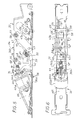
- the push bar door control device 10 conventionally extends transversely with respect to the door leaf between the boot 12 and an end cover 15 which is also fixed to said leaf.
- a support 18 formed from a metal U-shaped section, intended to be fixed against the door leaf and a support bar 20 mounted movably on the support and capable of a driving movement relative to this in response to a thrust stress exerted at any point of the bar. It is also made up of a metal profile with a U-shaped cross-section, the concavity of which is turned towards that of the support. The spacing of the two parallel lateral wings of the profile constituting the support bar 20 is here less than that of the two parallel wings of the profile constituting the support 18 so that said support bar can, when it is stressed, s' press inside the support.
- the support bar 20 and the support 18 are linked to each other by two guide modules 22 installed inside the section support 18 transverse in U.
- the guide modules 22 define the trajectory of the support bar in relation to the support. Said support bar is articulated to them.
- Each guide module 22 is itself arranged inside a section of metal profile 23 with generally U-shaped section. It comprises a transverse roller 24 movable in two lights 26 parallel and at about 45 ° of the plane of the door, made in the two parallel lateral flanges of this section of profile.
- the roller is extended axially, outside said flanges but inside the support by cylindrical pins 28 attached to the grab bar.
- the roller is biased by a spring 30 towards the outside of the base formed by said section of metal profile.
- rollers 24 thus biased towards the outside of the support 18 are susceptible to move aside the support bar 20 thereof while defining for the latter a predetermined sinking stroke.
- the lights 26 enters which move the rollers are at an angle to the direction longitudinal of the support 18, the depression of the support bar results in a longitudinal displacement thereof, suitable for actuating the door lock (or lock).
- the door control device is also equipped with means immobilization 34 of said support bar.
- These immobilization means are installed in an active locking module 35 also fixed to the bottom of the support 18, for example in place of a pre-existing guide module.
- the active locking module 35 is also arranged on a base 36 comprising a base plate 36a fixed to the support 18 and two flanges parallel side 36b between which are installed, in particular, trunnions forming part of the immobilization means in question.
- the module active locking also houses a guide module 22 constituted, as the other two, of a transverse roller 24 movable in parallel slots 26 made in the lateral flanges 36b of the base 36. This roller is extended axially outside the flanges by studs attached to the grab bar and the roller is biased towards the outside of said base (and therefore support) by a spring 30.
- the immobilization means 34 of the support bar comprise a locking mechanism 38 which will be described later, articulated, interposed between said support (more particularly said base 36 and said support bar 20), a suction cup 40 and a locking piece 42 whose movement is controlled by a movable element 44 of said suction cup.
- Locking piece 42 is susceptible, in a predetermined position given to it by said suction cup, to hold the locking mechanism 34 in a position preventing the driving movement of the support bar 20.
- the mechanism of blocking 38 comprises a chain of links 45, 46, 47 articulated end-to-end.
- the chain has three links.
- the two ends of said chain are articulated to the support (in fact to the flanges 36b of the base) by two pins 48, 49 with fixed axes, while the connecting rods are attached between them by joints 52, 53 of free axes.
- a free axis joint 52 carries a locking stop 56 cooperating with said piece of locking and the other articulation 53 carries a support stop 58 in contact with said grab bar.
- the geometry and kinematics of the locking mechanism are such that in a position of it that corresponds to a position not pressed in of said bar (FIGS. 3 and 4), the force to be exerted on the stop of lock 56 to contain a driving force applied to the stop support 58 is multiplied by a value depending on said geometry of the link mechanism in this position.
- the links of said chain are arranged approximately in "zig-zag" and, in the standby position of the support bar (that is to say the position not pressed ) the two end links 45, 47 of said chain make a small angle relative to a direction of the driving force indicated by the arrow F 1 in the drawings.
- the support stop and the locking stop are respectively formed by cylindrical rollers.
- the axis of rotation of the roller constituting the support stop 58 is coincident with that of the free-axis joint which carries it.
- the axis of rotation of the roller constituting the locking stop 56 is confused with that of the articulation of free axis which carries it.
- the link 45 is a link with several parallel branches forming a kind of yoke for the roller constituting the locking stop 56. It extends between the pin pin 48 mounted between the parallel flange lights of the base and the free-axis joint 52 which connects it to the central link 46 of the chain.
- the articulation 52 is materialized by an axis on which the roller is mounted rotating, said axis extending between two branches of the link 45.
- the other end link 47 of the chain is a twin link comprising two parallel branches joined by a transverse bridge 47 a .
- This twin link is articulated to the two flanges 36 b of the base (that is to say to the support itself) by the journal with a fixed axis 49, transverse, located closer to the bottom of the base than the pin 48 which carries the link 45.
- the twin link 47 carries a free-axis joint 53 by which it is connected to the central link 46.
- the roller 58 constituting the stop support is mounted in free rotation on this axis. It is in contact with the inner face of the support bar 20.
- a pin spring 60 is installed between the bottom of the base and the transverse bridge 47 a connecting the two branches of the twin link 47. It is wound around the journal 49. This spring therefore urges the support stop 58, that is to say the roller, towards the outside of the support, that is to say towards the support bar to maintain contact between the roller and the inner face of said support bar.
- the suction cup 40 is mounted on the base 36. It is more particularly fixed on a metal part 65 bent in L, fixed to the base so that the axis of the coil 40 a of the suction cup is arranged in bias, longitudinally relative to the support 18.
- the coil cooperates with the movable element 44 of the suction cup, comprising a kind of pole plate 44 a made of soft iron.
- This pole plate defines with the coil a variable gap area 64. This gap therefore defines the stroke of said movable element 44 and this stroke is extremely reduced. Consequently, said coil can exert on the movable element forming the pole plate 44 has a relatively large restoring force, all other things being equal.
- the movable element 44 is linked to a guide mechanism 66 imposing on it an approximately rectilinear trajectory. More specifically, the movable element 44 comprises a yoke and a flat link 67 is fixed to the side of this yoke. It has an oblong hole 68 in which engages a fixed rod 70 secured to the support, more precisely mounted between the two lateral flanges 36 b of the base.
- the guide mechanism is completed by a tension spring 72 mounted between the movable element 44 and a fixed anchoring point of the support, here the rod 70.
- This guide mechanism therefore limits the pivoting between the surface of the pole plate 44 a and the end face 75, facing the coil 40 a . Said pole plate therefore no longer risks being applied at an angle to the end face of the coil, which would result in poor "sticking" of the pole plate and therefore a defective active locking.
- the locking piece 42 mentioned above is installed between the yoke of the movable element 44 of said suction cup and the roller constituting said locking piece 56 of the locking mechanism 38. It is a flat piece pivotally mounted around a fixed axis 74 installed between the two flanges 36b of the base. It has an articulated extension to the yoke of the movable element (axis 76).
- the suction cup 40 therefore transforms this locking piece into a kind of pivoting lever.
- Said locking piece 42 includes a hook part 78 cooperating with the locking stop 56, that is to say in contact with the latter, in a position suitable for immobilizing it (FIG.
- the locking piece 42 has a part in an arc 80 extending the hook part.
- the center of this semicircle is substantially on the axis of the journal of fixed axis 48 on which the rod 45 pivots of the chain carrying the locking stop 56. The latter remains in contact with the part in a semicircle in case of depression of the support bar, as shown in Figure 5.
- the force F 1 necessary to overcome F 2 depends entirely on the geometry of the locking mechanism 38 in this position and in particular on the products D 1 .D 4 .D 5 and D 2 .D 3 .D 6 .
- the lengths D 1 , D 4 and D 5 being notably and visibly shorter than the lengths D 2 , D 3 and D 6 , it is understood that the retaining force which the suction cup must develop is relatively moderate, all other things being equal .
- a ratio of about 1 to 40 is obtained in three stages of reduction with simple parts to be made, of cut metal, because these parts all work in traction.
- the suction cup can therefore be fitted with a coil consuming relatively little electricity and of small dimensions.
- the system is also relatively compact.
- the stroke of the pole plate 44 a ensuring the blocking is very small and relatively well controlled. The force that the suction cup must develop is stable and reliable.
Landscapes
- Business, Economics & Management (AREA)
- Emergency Management (AREA)
- Lock And Its Accessories (AREA)
- Power-Operated Mechanisms For Wings (AREA)
- Hooks, Suction Cups, And Attachment By Adhesive Means (AREA)
- Orthopedics, Nursing, And Contraception (AREA)
Applications Claiming Priority (2)
| Application Number | Priority Date | Filing Date | Title |
|---|---|---|---|
| FR9902447 | 1999-02-26 | ||
| FR9902447A FR2790276B1 (fr) | 1999-02-26 | 1999-02-26 | Dispositif de commande de porte a barre de poussee, anti-panique, du type a condamnation active |
Publications (2)
| Publication Number | Publication Date |
|---|---|
| EP1031689A1 true EP1031689A1 (de) | 2000-08-30 |
| EP1031689B1 EP1031689B1 (de) | 2004-09-22 |
Family
ID=9542601
Family Applications (1)
| Application Number | Title | Priority Date | Filing Date |
|---|---|---|---|
| EP00400518A Expired - Lifetime EP1031689B1 (de) | 1999-02-26 | 2000-02-25 | Steuervorrichtung für eine Tür mit einer aktiv verriegelbaren Notausgangsgriffstange |
Country Status (4)
| Country | Link |
|---|---|
| EP (1) | EP1031689B1 (de) |
| AT (1) | ATE277254T1 (de) |
| DE (1) | DE60013932T8 (de) |
| FR (1) | FR2790276B1 (de) |
Cited By (5)
| Publication number | Priority date | Publication date | Assignee | Title |
|---|---|---|---|---|
| US7597237B2 (en) * | 2005-04-22 | 2009-10-06 | Regents Of The University Of Michigan | Rotatable multi-pin apparatus, and process for friction driven stitch welding and structural modification of materials |
| US20100123323A1 (en) * | 2008-11-17 | 2010-05-20 | Security Door Controls | Electric latch retraction bar |
| EP2348172A3 (de) * | 2010-01-25 | 2012-12-26 | BKS GmbH | Entriegelungsvorrichtung |
| US10107015B2 (en) | 2008-11-17 | 2018-10-23 | Security Door Controls | Electric latch retraction push-bar device |
| US20220018162A1 (en) * | 2019-01-28 | 2022-01-20 | Sargent Manufacturing Company | Universal dogging and electronic latch retraction |
Families Citing this family (1)
| Publication number | Priority date | Publication date | Assignee | Title |
|---|---|---|---|---|
| DE102021129656A1 (de) | 2021-11-15 | 2023-05-17 | Eco Schulte Gmbh & Co. Kg | Sperrvorrichtung |
Citations (5)
| Publication number | Priority date | Publication date | Assignee | Title |
|---|---|---|---|---|
| FR2591645A1 (fr) * | 1985-12-12 | 1987-06-19 | Ferte Sous Jouarre Const Elect | Mecanisme d'ouverture et de fermeture d'issue de secours |
| US4785286A (en) * | 1986-01-31 | 1988-11-15 | Martin Frank J | Alarm unit for panic bar type door operator |
| DE3716021A1 (de) * | 1987-05-14 | 1988-11-24 | Dorma Gmbh & Co Kg | Verriegelungseinrichtung fuer notausgangstueren |
| FR2622240A1 (fr) * | 1987-10-27 | 1989-04-28 | Chauvat Sofranq | Dispositif de fermeture antipanique de type " push-bar " a condamnation active |
| US5823582A (en) * | 1995-08-24 | 1998-10-20 | Harrow Products, Inc. | Electromagnetically-managed latching exit bar |
-
1999
- 1999-02-26 FR FR9902447A patent/FR2790276B1/fr not_active Expired - Fee Related
-
2000
- 2000-02-25 EP EP00400518A patent/EP1031689B1/de not_active Expired - Lifetime
- 2000-02-25 AT AT00400518T patent/ATE277254T1/de not_active IP Right Cessation
- 2000-02-25 DE DE60013932T patent/DE60013932T8/de active Active
Patent Citations (5)
| Publication number | Priority date | Publication date | Assignee | Title |
|---|---|---|---|---|
| FR2591645A1 (fr) * | 1985-12-12 | 1987-06-19 | Ferte Sous Jouarre Const Elect | Mecanisme d'ouverture et de fermeture d'issue de secours |
| US4785286A (en) * | 1986-01-31 | 1988-11-15 | Martin Frank J | Alarm unit for panic bar type door operator |
| DE3716021A1 (de) * | 1987-05-14 | 1988-11-24 | Dorma Gmbh & Co Kg | Verriegelungseinrichtung fuer notausgangstueren |
| FR2622240A1 (fr) * | 1987-10-27 | 1989-04-28 | Chauvat Sofranq | Dispositif de fermeture antipanique de type " push-bar " a condamnation active |
| US5823582A (en) * | 1995-08-24 | 1998-10-20 | Harrow Products, Inc. | Electromagnetically-managed latching exit bar |
Cited By (9)
| Publication number | Priority date | Publication date | Assignee | Title |
|---|---|---|---|---|
| US7597237B2 (en) * | 2005-04-22 | 2009-10-06 | Regents Of The University Of Michigan | Rotatable multi-pin apparatus, and process for friction driven stitch welding and structural modification of materials |
| US20100123323A1 (en) * | 2008-11-17 | 2010-05-20 | Security Door Controls | Electric latch retraction bar |
| US8851530B2 (en) * | 2008-11-17 | 2014-10-07 | 1 Adolfo, Llc | Electric latch retraction bar |
| US9797165B2 (en) | 2008-11-17 | 2017-10-24 | Security Door Controls | Electric latch retraction bar |
| US10107015B2 (en) | 2008-11-17 | 2018-10-23 | Security Door Controls | Electric latch retraction push-bar device |
| EP2348172A3 (de) * | 2010-01-25 | 2012-12-26 | BKS GmbH | Entriegelungsvorrichtung |
| US20220018162A1 (en) * | 2019-01-28 | 2022-01-20 | Sargent Manufacturing Company | Universal dogging and electronic latch retraction |
| US12006735B2 (en) | 2019-01-28 | 2024-06-11 | Sargent Manufacturing Company | Universal dogging and electronic latch retraction |
| US12071789B2 (en) * | 2019-01-28 | 2024-08-27 | Sargent Manufacturing Company | Universal dogging and electronic latch retraction |
Also Published As
| Publication number | Publication date |
|---|---|
| DE60013932D1 (de) | 2004-10-28 |
| EP1031689B1 (de) | 2004-09-22 |
| DE60013932T8 (de) | 2006-06-01 |
| FR2790276A1 (fr) | 2000-09-01 |
| FR2790276B1 (fr) | 2001-06-01 |
| ATE277254T1 (de) | 2004-10-15 |
| DE60013932T2 (de) | 2005-10-06 |
Similar Documents
| Publication | Publication Date | Title |
|---|---|---|
| FR2576961A1 (fr) | Mecanisme d'assistance a la fermeture d'une porte d'un vehicule automobile | |
| FR2705064A1 (fr) | Crochet d'accouplement pour les bras inférieurs d'un dispositif d'attelage trois points d'un tracteur. | |
| EP1031689B1 (de) | Steuervorrichtung für eine Tür mit einer aktiv verriegelbaren Notausgangsgriffstange | |
| EP1404605B1 (de) | Verriegelungsvorrichtung für schachttür mit unabhängiger notentriegelungsvorrichtung | |
| FR2523939A1 (fr) | Dispositif de verrouillage pour empecher l'ouverture de la porte d'une cabine d'ascenseur entre les etages | |
| EP2565353B1 (de) | Vorrichtung zum Verriegeln und Entriegeln mit Hilfe eines Schlüssels einer Abdeckung auf einem Rahmen mit integrierter Verschlusseinlage eines Öffnungselements der Abdeckung für das Einführen des Schlüssels | |
| FR2668790A1 (fr) | Dispositif de fermeture anti-panique controle. | |
| WO2002025041A1 (fr) | Mecanisme de manoeuvre de porte | |
| EP1023513B1 (de) | Sicherheitsschloss, insbesondere für aufzugsschachttür | |
| FR2743105A1 (fr) | Serrure a verrou a claquer | |
| FR2685310A1 (fr) | Mecanisme pour l'introduction d'un objet plat vers un dispositif de traitement dudit objet. | |
| FR2653929A1 (fr) | Mobile d'actionnement a cle pour interrupteur de securite. | |
| WO2016091587A1 (fr) | Serrure pour un ouvrant de véhicule automobile | |
| EP1031688A1 (de) | Steuervorrichtung für eine Tür mit einer Notausgangsgriffstange mit einem eine äussere elektrische Verbindung brauchenden elektrischen Bauelement | |
| FR2869340A1 (fr) | Dispositif d'ouverture d'un ouvrant de vehicule automobile muni de moyens pour empecher l'ouverture de l'ouvrant en cas de choc lateral | |
| EP3569552B1 (de) | Steuervorrichtung eines ver-/entriegelungsorgans eines öffnungsflügels auf einem rahmen, wie einem riegel, und diese umfassendes schloss | |
| EP0086685B1 (de) | Bedienungshebel | |
| EP0837208B1 (de) | Treibstangenbremsevorrichtung und Schiebeflügel mit einer solchen Vorrichtung | |
| BE1011952A4 (fr) | Dispositif de verrouillage d'un ouvrant sur un dormant par des moyens electromagnetiques. | |
| EP2299039B1 (de) | Verriegelungs-/Entriegelungsvorrichtung eines Garagentors oder Ähnlichem | |
| EP0297971B1 (de) | Vorrichtung zum Öffnen und Schliessen von Türen mit der Möglichkeit einer Zwischenöffnung, insbesondere für Drahtseilbahnkabinen | |
| EP0860126B1 (de) | System zur Befestigung eines Stellgliedes an einer Stange | |
| FR2795445A1 (fr) | Serrure electrique a decondamnation automatique a l'ouverture, notamment pour ouvrant de vehicule automobile | |
| FR2663361A1 (fr) | Fut, notamment pour candelabre d'eclairage public, et mecanisme d'articulation adapte a relier une porte de visite au reste du fut. | |
| FR2845110A1 (fr) | Arret de battant, notamment arret de porte |
Legal Events
| Date | Code | Title | Description |
|---|---|---|---|
| PUAI | Public reference made under article 153(3) epc to a published international application that has entered the european phase |
Free format text: ORIGINAL CODE: 0009012 |
|
| AK | Designated contracting states |
Kind code of ref document: A1 Designated state(s): AT BE CH CY DE DK ES FI FR GB GR IE IT LI LU MC NL PT SE |
|
| AX | Request for extension of the european patent |
Free format text: AL;LT;LV;MK;RO;SI |
|
| RIN1 | Information on inventor provided before grant (corrected) |
Inventor name: SALLET, ERIC |
|
| 17P | Request for examination filed |
Effective date: 20000925 |
|
| AKX | Designation fees paid |
Free format text: AT BE CH CY DE DK ES FI FR GB GR IE IT LI LU MC NL PT SE |
|
| GRAP | Despatch of communication of intention to grant a patent |
Free format text: ORIGINAL CODE: EPIDOSNIGR1 |
|
| GRAS | Grant fee paid |
Free format text: ORIGINAL CODE: EPIDOSNIGR3 |
|
| GRAA | (expected) grant |
Free format text: ORIGINAL CODE: 0009210 |
|
| AK | Designated contracting states |
Kind code of ref document: B1 Designated state(s): AT BE CH CY DE DK ES FI FR GB GR IE IT LI LU MC NL PT SE |
|
| PG25 | Lapsed in a contracting state [announced via postgrant information from national office to epo] |
Ref country code: AT Free format text: LAPSE BECAUSE OF FAILURE TO SUBMIT A TRANSLATION OF THE DESCRIPTION OR TO PAY THE FEE WITHIN THE PRESCRIBED TIME-LIMIT Effective date: 20040922 Ref country code: FI Free format text: LAPSE BECAUSE OF FAILURE TO SUBMIT A TRANSLATION OF THE DESCRIPTION OR TO PAY THE FEE WITHIN THE PRESCRIBED TIME-LIMIT Effective date: 20040922 Ref country code: IE Free format text: LAPSE BECAUSE OF FAILURE TO SUBMIT A TRANSLATION OF THE DESCRIPTION OR TO PAY THE FEE WITHIN THE PRESCRIBED TIME-LIMIT Effective date: 20040922 Ref country code: NL Free format text: LAPSE BECAUSE OF FAILURE TO SUBMIT A TRANSLATION OF THE DESCRIPTION OR TO PAY THE FEE WITHIN THE PRESCRIBED TIME-LIMIT Effective date: 20040922 |
|
| REG | Reference to a national code |
Ref country code: GB Ref legal event code: FG4D Free format text: NOT ENGLISH |
|
| REG | Reference to a national code |
Ref country code: CH Ref legal event code: EP |
|
| REG | Reference to a national code |
Ref country code: IE Ref legal event code: FG4D Free format text: FRENCH |
|
| REF | Corresponds to: |
Ref document number: 60013932 Country of ref document: DE Date of ref document: 20041028 Kind code of ref document: P |
|
| PG25 | Lapsed in a contracting state [announced via postgrant information from national office to epo] |
Ref country code: DK Free format text: LAPSE BECAUSE OF FAILURE TO SUBMIT A TRANSLATION OF THE DESCRIPTION OR TO PAY THE FEE WITHIN THE PRESCRIBED TIME-LIMIT Effective date: 20041222 Ref country code: GR Free format text: LAPSE BECAUSE OF FAILURE TO SUBMIT A TRANSLATION OF THE DESCRIPTION OR TO PAY THE FEE WITHIN THE PRESCRIBED TIME-LIMIT Effective date: 20041222 Ref country code: SE Free format text: LAPSE BECAUSE OF FAILURE TO SUBMIT A TRANSLATION OF THE DESCRIPTION OR TO PAY THE FEE WITHIN THE PRESCRIBED TIME-LIMIT Effective date: 20041222 |
|
| PG25 | Lapsed in a contracting state [announced via postgrant information from national office to epo] |
Ref country code: ES Free format text: LAPSE BECAUSE OF FAILURE TO SUBMIT A TRANSLATION OF THE DESCRIPTION OR TO PAY THE FEE WITHIN THE PRESCRIBED TIME-LIMIT Effective date: 20050102 |
|
| RAP2 | Party data changed (patent owner data changed or rights of a patent transferred) |
Owner name: JPM SAS |
|
| GBT | Gb: translation of ep patent filed (gb section 77(6)(a)/1977) |
Effective date: 20050116 |
|
| PG25 | Lapsed in a contracting state [announced via postgrant information from national office to epo] |
Ref country code: LU Free format text: LAPSE BECAUSE OF NON-PAYMENT OF DUE FEES Effective date: 20050225 Ref country code: CY Free format text: LAPSE BECAUSE OF FAILURE TO SUBMIT A TRANSLATION OF THE DESCRIPTION OR TO PAY THE FEE WITHIN THE PRESCRIBED TIME-LIMIT Effective date: 20050225 |
|
| PG25 | Lapsed in a contracting state [announced via postgrant information from national office to epo] |
Ref country code: CH Free format text: LAPSE BECAUSE OF NON-PAYMENT OF DUE FEES Effective date: 20050228 Ref country code: LI Free format text: LAPSE BECAUSE OF NON-PAYMENT OF DUE FEES Effective date: 20050228 Ref country code: MC Free format text: LAPSE BECAUSE OF NON-PAYMENT OF DUE FEES Effective date: 20050228 |
|
| NLT2 | Nl: modifications (of names), taken from the european patent patent bulletin |
Owner name: JPM SAS |
|
| NLV1 | Nl: lapsed or annulled due to failure to fulfill the requirements of art. 29p and 29m of the patents act | ||
| REG | Reference to a national code |
Ref country code: IE Ref legal event code: FD4D |
|
| PLBE | No opposition filed within time limit |
Free format text: ORIGINAL CODE: 0009261 |
|
| STAA | Information on the status of an ep patent application or granted ep patent |
Free format text: STATUS: NO OPPOSITION FILED WITHIN TIME LIMIT |
|
| 26N | No opposition filed |
Effective date: 20050623 |
|
| REG | Reference to a national code |
Ref country code: CH Ref legal event code: PL |
|
| REG | Reference to a national code |
Ref country code: HK Ref legal event code: WD Ref document number: 1030971 Country of ref document: HK |
|
| PG25 | Lapsed in a contracting state [announced via postgrant information from national office to epo] |
Ref country code: PT Free format text: LAPSE BECAUSE OF NON-PAYMENT OF DUE FEES Effective date: 20050222 |
|
| PG25 | Lapsed in a contracting state [announced via postgrant information from national office to epo] |
Ref country code: IT Free format text: LAPSE BECAUSE OF NON-PAYMENT OF DUE FEES Effective date: 20080225 |
|
| PGRI | Patent reinstated in contracting state [announced from national office to epo] |
Ref country code: IT Effective date: 20110616 |
|
| REG | Reference to a national code |
Ref country code: FR Ref legal event code: PLFP Year of fee payment: 17 |
|
| PGFP | Annual fee paid to national office [announced via postgrant information from national office to epo] |
Ref country code: IT Payment date: 20160222 Year of fee payment: 17 Ref country code: DE Payment date: 20160216 Year of fee payment: 17 |
|
| PGFP | Annual fee paid to national office [announced via postgrant information from national office to epo] |
Ref country code: FR Payment date: 20160108 Year of fee payment: 17 Ref country code: BE Payment date: 20160113 Year of fee payment: 17 Ref country code: GB Payment date: 20160224 Year of fee payment: 17 |
|
| PG25 | Lapsed in a contracting state [announced via postgrant information from national office to epo] |
Ref country code: BE Free format text: LAPSE BECAUSE OF NON-PAYMENT OF DUE FEES Effective date: 20170228 |
|
| REG | Reference to a national code |
Ref country code: DE Ref legal event code: R119 Ref document number: 60013932 Country of ref document: DE |
|
| GBPC | Gb: european patent ceased through non-payment of renewal fee |
Effective date: 20170225 |
|
| REG | Reference to a national code |
Ref country code: FR Ref legal event code: ST Effective date: 20171031 |
|
| PG25 | Lapsed in a contracting state [announced via postgrant information from national office to epo] |
Ref country code: DE Free format text: LAPSE BECAUSE OF NON-PAYMENT OF DUE FEES Effective date: 20170901 Ref country code: FR Free format text: LAPSE BECAUSE OF NON-PAYMENT OF DUE FEES Effective date: 20170228 |
|
| REG | Reference to a national code |
Ref country code: BE Ref legal event code: MM Effective date: 20170228 |
|
| PG25 | Lapsed in a contracting state [announced via postgrant information from national office to epo] |
Ref country code: IT Free format text: LAPSE BECAUSE OF NON-PAYMENT OF DUE FEES Effective date: 20170225 Ref country code: GB Free format text: LAPSE BECAUSE OF NON-PAYMENT OF DUE FEES Effective date: 20170225 |