EP1030987B1 - Restdruckventil - Google Patents
Restdruckventil Download PDFInfo
- Publication number
- EP1030987B1 EP1030987B1 EP98955559A EP98955559A EP1030987B1 EP 1030987 B1 EP1030987 B1 EP 1030987B1 EP 98955559 A EP98955559 A EP 98955559A EP 98955559 A EP98955559 A EP 98955559A EP 1030987 B1 EP1030987 B1 EP 1030987B1
- Authority
- EP
- European Patent Office
- Prior art keywords
- valve
- closing element
- residual pressure
- compression spring
- actuating element
- Prior art date
- Legal status (The legal status is an assumption and is not a legal conclusion. Google has not performed a legal analysis and makes no representation as to the accuracy of the status listed.)
- Expired - Lifetime
Links
- 239000007789 gas Substances 0.000 claims abstract description 44
- 230000006835 compression Effects 0.000 claims description 15
- 238000007906 compression Methods 0.000 claims description 15
- 230000008878 coupling Effects 0.000 claims 1
- 238000010168 coupling process Methods 0.000 claims 1
- 238000005859 coupling reaction Methods 0.000 claims 1
- 238000007789 sealing Methods 0.000 description 4
- 239000012528 membrane Substances 0.000 description 3
- 230000008901 benefit Effects 0.000 description 2
- 230000003750 conditioning effect Effects 0.000 description 2
- 238000011109 contamination Methods 0.000 description 2
- 238000000034 method Methods 0.000 description 2
- 230000004048 modification Effects 0.000 description 2
- 238000012986 modification Methods 0.000 description 2
- 238000004381 surface treatment Methods 0.000 description 2
- 230000005540 biological transmission Effects 0.000 description 1
- 230000000903 blocking effect Effects 0.000 description 1
- 230000001143 conditioned effect Effects 0.000 description 1
- 230000007423 decrease Effects 0.000 description 1
- 230000001419 dependent effect Effects 0.000 description 1
- 230000000694 effects Effects 0.000 description 1
- 229920001971 elastomer Polymers 0.000 description 1
- 239000000806 elastomer Substances 0.000 description 1
- 238000005516 engineering process Methods 0.000 description 1
- 239000000945 filler Substances 0.000 description 1
- 238000004519 manufacturing process Methods 0.000 description 1
- 230000007246 mechanism Effects 0.000 description 1
- 239000002245 particle Substances 0.000 description 1
- 238000002203 pretreatment Methods 0.000 description 1
- 230000002265 prevention Effects 0.000 description 1
- 230000008569 process Effects 0.000 description 1
- 239000003507 refrigerant Substances 0.000 description 1
- 230000007704 transition Effects 0.000 description 1
Images
Classifications
-
- F—MECHANICAL ENGINEERING; LIGHTING; HEATING; WEAPONS; BLASTING
- F16—ENGINEERING ELEMENTS AND UNITS; GENERAL MEASURES FOR PRODUCING AND MAINTAINING EFFECTIVE FUNCTIONING OF MACHINES OR INSTALLATIONS; THERMAL INSULATION IN GENERAL
- F16K—VALVES; TAPS; COCKS; ACTUATING-FLOATS; DEVICES FOR VENTING OR AERATING
- F16K1/00—Lift valves or globe valves, i.e. cut-off apparatus with closure members having at least a component of their opening and closing motion perpendicular to the closing faces
- F16K1/30—Lift valves or globe valves, i.e. cut-off apparatus with closure members having at least a component of their opening and closing motion perpendicular to the closing faces specially adapted for pressure containers
- F16K1/301—Lift valves or globe valves, i.e. cut-off apparatus with closure members having at least a component of their opening and closing motion perpendicular to the closing faces specially adapted for pressure containers only shut-off valves, i.e. valves without additional means
- F16K1/302—Lift valves or globe valves, i.e. cut-off apparatus with closure members having at least a component of their opening and closing motion perpendicular to the closing faces specially adapted for pressure containers only shut-off valves, i.e. valves without additional means with valve member and actuator on the same side of the seat
-
- F—MECHANICAL ENGINEERING; LIGHTING; HEATING; WEAPONS; BLASTING
- F17—STORING OR DISTRIBUTING GASES OR LIQUIDS
- F17C—VESSELS FOR CONTAINING OR STORING COMPRESSED, LIQUEFIED OR SOLIDIFIED GASES; FIXED-CAPACITY GAS-HOLDERS; FILLING VESSELS WITH, OR DISCHARGING FROM VESSELS, COMPRESSED, LIQUEFIED, OR SOLIDIFIED GASES
- F17C2227/00—Transfer of fluids, i.e. method or means for transferring the fluid; Heat exchange with the fluid
- F17C2227/04—Methods for emptying or filling
- F17C2227/048—Methods for emptying or filling by maintaining residual pressure
Definitions
- the invention relates to a valve with an integrated residual pressure device, containing a Closing element which is pressed onto the valve seat by a compression spring and by means of an actuating element which is not firmly connected to the closing element can be brought into the blocking position.
- compressed gas tanks should not be completely emptied, but with a residual pressure of 2 - 3 bar overpressure. This residual pressure ensures that the internal surface treatment of the compressed gas containers is preserved and no atmosphere can penetrate.
- the inner surface becomes very expensive conditioned through targeted treatment procedures to gases the Purity 6.0 or stable test gases can be saved.
- Compressed gas cylinders are often completely emptied (1 bar absolute) and the cylinder valves not closed. The result is that the surface treatment and conditioning is destroyed by the ingress of air.
- the compressed gas bottle is not refillable, but must undergo basic treatment again become. This creates unnecessary costs.
- EP 0 077 828-B1 describes a valve with a pressure-dependent closing device (Residual pressure valve), the local and functional of the shut-off valve contained in the valve is separated.
- GB-A-1 022 522 describes a valve with an integrated residual pressure valve, whereby the Handwheel acts on the locking element via a threaded part. Threaded part and Locking elements are separate parts. For filling a compressed gas bottle with the valve, a screw part on the head of the Valves are removed.
- DE 42 14 544 A1 relates to a closure and filling valve for containers with an under Pressurized medium, especially for refrigerant bottles. It will be a valve described, the closure body of a pressure-tight in the valve housing and piston is preloaded by means of a closing spring.
- valves are usually O-ring valves with complicated inner functional geometries. Such valves are for use in the ultra-pure gas sector not suitable.
- the invention has for its object a shut-off valve with an integrated residual pressure valve which is suitable for ultra pure gas applications.
- the closing element which is pressed onto the valve seat by a compression spring, acts as a residual pressure valve. Residual pressure valves close when a certain value is undershot Bottle pressure (e.g. 2 - 3 bar) automatically by mechanical elements the gas space of a compressed gas bottle.
- the handwheel does not have to be operated here, i.e. the valve is closed in any case - even if you forget it close.
- the functional and design principle can generally be used with all valve types. Use with shut-off elements with a diaphragm valve is particularly advantageous or stuffing box valve. In particular, the valve according to the invention is at Ultrapure gases are a great advantage.
- the residual pressure device of the valve is preferably in the non-gas contact Valve space shifted.
- the residual pressure device for diaphragm valves arranged above the membrane and in the area of the upper spindle.
- the residual pressure device in the Usually installed in common valves.
- the manufacture of the valves according to The invention is therefore very economical, since existing valve parts (e.g. Valve body) can be used.
- the compression spring of the residual pressure device is advantageous in the cap screw arranged and exerts an axial force on the valve seat.
- the valve spindle (upper spindle for diaphragm valves) is preferably without Spindle thread and movable in the cap screw.
- the cap screw preferably contains a thread (e.g. internal thread) in which a part of the Actuator is guided with a suitable thread.
- a thread turns the actuating element (handwheel) into an opening or Implemented from hub. This presses in the closed position of the valve Actuator on the closing element (valve stem) and thus fixes that Closing element sealing on the valve seat. The gas path is blocked.
- valve If you open the valve (turn the handwheel to open), it will axially movable closing element is no longer mechanically fixed and can Carry out residual pressure control.
- the spring exerts one directed towards the valve seat Force in the closing direction. This force is the pressure force of the gas pressure of the compressed gas container and opens the closing element against the Spring force.
- the stroke is, for example, by an edge in the cap screw limited.
- the pressure of the gas decreases with increasing emptying.
- the spring force is designed in this way (e.g. fixed by the spring force of the compression spring used predefined) that they reach or fall below the gas pressure in the Compressed gas content of e.g. B. 2 - 3 bar predominates and the closing element closes. In this way there is a residual pressure in the pressure gas container guaranteed and the valve closed. Gas from the atmosphere cannot penetrate the compressed gas tank.
- the closing element can be an extension with, for example Have drivers (e.g. stop) at the upper end, with the Extension (e.g. cylindrical pin) advantageous through a central opening is guided in the actuator and the driver only when the Actuating element beyond the closed position on the actuating element engages and the closing element mechanically against the pressure spring force is opened.
- the valve in the cap screw advantageously has one defined stop against a further pulling up of the closing element the compression spring force prevents.
- the bypass of the residual pressure control is at normal opening of the valve is not effective.
- the bridging device of the residual pressure control is preferably designed so that the bridging function for unauthorized persons is not can be operated, for. B. by a built-in lock or fuse that can only be removed from the gas filler.
- the bridging device is, for example, by suitable coding measures before manipulation by the user / customer accordingly secured and can only be picked up by the filling staff with suitable means become.
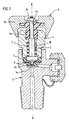
- Fig. 1 shows a valve according to the invention using the example of a diaphragm valve (Longitudinal section along axis A-A).
- the valve body 1 contains the Gas channels, the valve seat 1a, an opening with an internal thread for receiving the cap screw 4 and the functional parts closing element 2, compression spring 3, Membrane 6 and seal 7.
- the actuator 5, consisting of Threaded part 5a and associated handwheel 5b, in a thread central opening of the cap screw 4 out. Rotation of the actuator leads to an up or down movement depending on the direction of rotation.
- housed compression spring with the middle shaft 2b of the Closing element 2 (part of the upper spindle) essentially forms the Residual pressure control.
- the opening of the closing element 2 is by a Narrowing of the central opening of the cap screw 4 limited (stop of the head of the upper spindle on the edge of the constriction).
- the valve membrane is between the head of the upper spindle and the lower spindle 2a 6 arranged.
- the underside of the lower spindle 2a preferably with Sealing element equipped, seals against the valve seat 1a in the closed Position.
- the closing element has no thread for power transmission in an up or down movement and the actuator 5 is not coupled. Nevertheless, the closing element and pressure control form one unit. To close the valve (lowering the closing element 2), this takes effect Threaded part 5a from a certain position on the shaft of the Closing element 2 (edge at the transition from middle shaft 2b to narrower extension 2c).
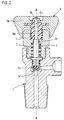
- FIG. 2 shows a valve according to the invention using the example of a stuffing box valve (Longitudinal section along axis A-A) with an analogous structure to Fig. 1.
- the Valve main body 1 contains the gas channels, the valve seat 1a, with an opening Internal thread for receiving the cap screw 4 and the functional parts Closing element 2 and compression spring 3. Closing element 2 and actuating element 5 are without a direct connection.
- Residual pressure control device with compression spring 3 and closing element 2 effective.
- the Head 2a of the valve spindle presses against valve seat 1a. Exceeds the force of the applied gas pressure, the spring force of the compression spring 3, so it will Closing element raised and gas can escape.
- valve position presses the actuating element 5 with the threaded part 5a Closing element 2, whereby the head 2a of the valve spindle against the valve seat 1a pressed and the valve is closed.
- the head 2a is on the sealing side with a seal (e.g. sealing ring made of elastomer) fitted.
Landscapes
- Engineering & Computer Science (AREA)
- General Engineering & Computer Science (AREA)
- Mechanical Engineering (AREA)
- Filling Or Discharging Of Gas Storage Vessels (AREA)
- Jib Cranes (AREA)
- Valves And Accessory Devices For Braking Systems (AREA)
- Safety Valves (AREA)
Description
- unzureichender Leitwert für die Flaschenkonitionierung,
- schlecht spürbare und damit kontaminationsträchtige innere Funktionsgeometrien,
- eine vielzahl federbelastete mechanische Funktionsbauteile (führt zur Partikelerzeugung).
- Innere Funktionsgeometrie mit der gleichen Kontaminationsarmut wie bei klassischen Reinstgasventilen,
- Schutz der hochwertigen Druckgasbehälterinnenvorbehandlung führt zu Kosten-ersparnis,
- Sicherheit, daß die Innenvorbehandlung der Druckgasbehälter über die Umlaufzyklen konserviert bleibt (Ersparnis von Überprüfungen),
- Schutz vor Kontamination der Druckgasbehälter bei normalem Handling,
- definiertes Entlasten der Restinhalte für innerbetriebliche Abläufe,
- bestehende Ventiltechnologie kann relativ preiswert umgerüstet bzw. modifiziert werden,
- Funktionsprinzip auf andere Ventiltypen übertragbar.
Claims (9)
- Ventil mit integrierter Restdruckeinrichtung, enthaltend ein Schließelement (2), das durch eine Druckfeder (3) auf den Ventilsitz (1a) gedrücht wird und mittels eines mit dem Schließelement (2) nicht fest verbundenen Betätigungselements (5) in absperrende Stellung gebracht werden kann, dadurch gekennzeichnet, daß das Ventil eine Oberbrückungseinrichtung zur Herstellung einer direkten Kopplung zwischen Schließelement (2) und Betätigungselement (5) enthält.
- Ventil nach Anspruch 1, dadurch gekennzeichnet, daß die Druckfeder (3) in der Kopfschraube (4) des Ventiles angeordnet ist.
- Ventil nach Anspruch 1 oder 2, dadurch gekennzeichnet, daß die Restdruckeinrichtung des Ventils im nicht gasberührten Raum des Ventils angeordnet ist
- Ventil nach einem der Ansprüche 1. bis 3,
dadurch gekennzeichnet, daß das Schließelement (2) eine Verlängerung mit einem Mitnehmer am oberen Ende aufweist, wobei die Verlängerung (2c) durch eine zentrale Öffnung im Betätigungselement (5) geführt wird und der Mitnehmer (2d) erst bei Drehung des Betätigungselementes (5) über die Verschlußstellung hinaus am Betätigungselement (5) greift und das Schließelement (2) gegen die Kraft der Druckfeder (3) mechanisch geöffnet wird. - Ventil nach einem der Ansprüche 1 bis 4, dadurch gekennzeichnet, daß das Ventil in der Kopfschraube (4) einen definierten Anschlag besitzt, der ein weiteres Hochziehen des Schließelementes (2) gegen die Kraft der Druckfeder (3) verhindert.
- Ventil nach einem der Ansprüche 1 bis 5, dadurch gekennzeichnet, daß das Ventil vom Typ eines Membranventiles, eines Faltenbalgventiles oder eines Stopfbuchsventiles ist.
- Druckgasbehälter mit einem Ventil nach einem der Ansprüche 1 bis 6.
- Verwendung eines Ventils gemäß einem der Ansprüche 1 bis 6 als Absperrventil für Druckgasbehälter.
- Verwendung eines Ventils gemäß einem der Ansprüche 1 bis 6 für Reinstgase.
Applications Claiming Priority (3)
| Application Number | Priority Date | Filing Date | Title |
|---|---|---|---|
| DE19751678 | 1997-11-21 | ||
| DE19751678A DE19751678A1 (de) | 1997-11-21 | 1997-11-21 | Restdruckventil |
| PCT/EP1998/007158 WO1999027282A1 (de) | 1997-11-21 | 1998-11-10 | Restdruckventil |
Publications (2)
| Publication Number | Publication Date |
|---|---|
| EP1030987A1 EP1030987A1 (de) | 2000-08-30 |
| EP1030987B1 true EP1030987B1 (de) | 2002-05-02 |
Family
ID=7849458
Family Applications (1)
| Application Number | Title | Priority Date | Filing Date |
|---|---|---|---|
| EP98955559A Expired - Lifetime EP1030987B1 (de) | 1997-11-21 | 1998-11-10 | Restdruckventil |
Country Status (4)
| Country | Link |
|---|---|
| EP (1) | EP1030987B1 (de) |
| AT (1) | ATE217057T1 (de) |
| DE (2) | DE19751678A1 (de) |
| WO (1) | WO1999027282A1 (de) |
Families Citing this family (4)
| Publication number | Priority date | Publication date | Assignee | Title |
|---|---|---|---|---|
| GB0221554D0 (en) * | 2002-09-17 | 2002-10-23 | Boc Group Plc | Cylinder valve |
| CN108443529B (zh) * | 2018-05-08 | 2019-07-02 | 上海皓固机械工业有限公司 | 一种膜片阀 |
| US11885419B1 (en) | 2022-07-08 | 2024-01-30 | Ultra Flow Holdings, LLC | Pressure regulating valve |
| US12311142B2 (en) | 2023-04-25 | 2025-05-27 | The Esab Group, Inc. | Medical pin index residual pressure valve |
Family Cites Families (12)
| Publication number | Priority date | Publication date | Assignee | Title |
|---|---|---|---|---|
| DE688253C (de) * | 1936-06-14 | 1940-02-16 | Draegerwerk Heinr U Bernh Drae | Verschlussventil fuer Behaelter, insbesondere fuer Sauerstoffflaschen von Atemschutzgeraeten |
| DE835969C (de) * | 1950-03-03 | 1952-04-07 | Linde Eismasch Ag | Verfahren zur Verhuetung der Verunreinigung wertvoller Gase in Stahlflaschen und Ventil zur Durchfuehrung des Verfahrens |
| FR1370689A (fr) * | 1963-07-02 | 1964-08-28 | Air Liquide | Robinet pour récipient à gaz sous pression |
| DE2206561A1 (de) * | 1972-02-11 | 1973-08-23 | Messer Griesheim Gmbh | Ventil |
| US4402340A (en) * | 1981-05-01 | 1983-09-06 | Lockwood Jr Hanford N | Pressure-responsive shut-off valve |
| DE3928678C1 (de) * | 1989-08-30 | 1990-12-20 | Messer Griesheim Gmbh, 6000 Frankfurt, De | |
| LU87607A1 (de) * | 1989-10-11 | 1990-02-07 | Ceodeux Sa | Ventilanordnung mit restdruckventil zum fuellen und entleeren eines gasbehaelters |
| DE3935171A1 (de) * | 1989-10-21 | 1991-04-25 | Messer Griesheim Gmbh | Membranventil |
| LU87671A1 (fr) * | 1990-01-31 | 1990-05-15 | Ceodeux Sa | Robinet pour gaz comprime ou liquifie |
| DE4214544C2 (de) * | 1992-04-29 | 1997-06-19 | Dieter Oelkers | Verschluß- und Füllventil |
| US5516078A (en) * | 1994-08-16 | 1996-05-14 | Amcast Industrial Corporation | Gas cylinder valve with non-perforated diaphragms |
| IT1271025B (it) * | 1994-10-20 | 1997-05-26 | Patreca Srl | Valvola per bombole ad alta pressione con dispositivo per il mantenimento di una pressione residua allo svuotamento |
-
1997
- 1997-11-21 DE DE19751678A patent/DE19751678A1/de not_active Ceased
-
1998
- 1998-11-10 AT AT98955559T patent/ATE217057T1/de not_active IP Right Cessation
- 1998-11-10 WO PCT/EP1998/007158 patent/WO1999027282A1/de not_active Ceased
- 1998-11-10 DE DE59804006T patent/DE59804006D1/de not_active Expired - Lifetime
- 1998-11-10 EP EP98955559A patent/EP1030987B1/de not_active Expired - Lifetime
Also Published As
| Publication number | Publication date |
|---|---|
| EP1030987A1 (de) | 2000-08-30 |
| DE19751678A1 (de) | 1999-06-02 |
| WO1999027282A1 (de) | 1999-06-03 |
| DE59804006D1 (de) | 2002-06-06 |
| ATE217057T1 (de) | 2002-05-15 |
Similar Documents
| Publication | Publication Date | Title |
|---|---|---|
| DE1900854U (de) | Hahn fuer druckgasbehaelter. | |
| DE3419736A1 (de) | Ausgabe- und sicherheitsventil fuer einen sahnesiphon o. dgl. | |
| EP0788591A1 (de) | Anschlusssystem für eine druckgasflasche | |
| DE4101735A1 (de) | Hahn fuer druck- und fluessiggas | |
| DE3819689C2 (de) | Absperrventil | |
| EP1030987A1 (de) | Restdruckventil | |
| DE60004180T2 (de) | Gasflaschenventil | |
| DE60127448T2 (de) | Servogesteuertes sicherheitsventil für behälter für toxische fluide | |
| DE69504873T2 (de) | Auslass-und füllgerät für eine gasflasche | |
| DE3507263C2 (de) | Unter Behälterdruck austauschbares Sicherheitsventil | |
| DE839891C (de) | Flaschenverschluss, insbesondere fuer Behaelter mit hochgespannten Gasen | |
| DE2551696A1 (de) | Flaschenventil fuer atemgeraete mit restdruckgasvorrat | |
| DE60121617T2 (de) | Ventile | |
| EP0912849B1 (de) | Einschraubventil für einen druckbehälter | |
| DE1450627A1 (de) | Behaelter fuer ein unter Druck stehendes Fluidum | |
| DE2447648C2 (de) | Druckluftbremseinrichtung für Schienenfahrzeuge | |
| DE69612793T2 (de) | Elastischer Ventilhandgriff | |
| DE2018147A1 (de) | Reserveschalter für eine Taucherausrüstung | |
| DE69205516T2 (de) | Druckregelventil. | |
| DE19908587A1 (de) | Belüftungsventil für einen Kraftstoffbehälter | |
| GB2289754A (en) | Pressure reduction valve | |
| DE599942C (de) | Verschlussmutter fuer Brennstoffbehaelter von Koch-, Heiz- oder Beleuchtungsgeraeten | |
| DE1837802U (de) | Membranventil. | |
| DE7627477U1 (de) | Flaschenventil fuer atemgeraete | |
| EP0107186A1 (de) | Schieber mit zweifacher Rückdichtung |
Legal Events
| Date | Code | Title | Description |
|---|---|---|---|
| PUAI | Public reference made under article 153(3) epc to a published international application that has entered the european phase |
Free format text: ORIGINAL CODE: 0009012 |
|
| 17P | Request for examination filed |
Effective date: 20000621 |
|
| AK | Designated contracting states |
Kind code of ref document: A1 Designated state(s): AT BE CH DE ES FR GB LI NL |
|
| GRAG | Despatch of communication of intention to grant |
Free format text: ORIGINAL CODE: EPIDOS AGRA |
|
| 17Q | First examination report despatched |
Effective date: 20010709 |
|
| GRAG | Despatch of communication of intention to grant |
Free format text: ORIGINAL CODE: EPIDOS AGRA |
|
| GRAH | Despatch of communication of intention to grant a patent |
Free format text: ORIGINAL CODE: EPIDOS IGRA |
|
| GRAG | Despatch of communication of intention to grant |
Free format text: ORIGINAL CODE: EPIDOS AGRA |
|
| GRAH | Despatch of communication of intention to grant a patent |
Free format text: ORIGINAL CODE: EPIDOS IGRA |
|
| REG | Reference to a national code |
Ref country code: GB Ref legal event code: IF02 |
|
| GRAH | Despatch of communication of intention to grant a patent |
Free format text: ORIGINAL CODE: EPIDOS IGRA |
|
| GRAA | (expected) grant |
Free format text: ORIGINAL CODE: 0009210 |
|
| AK | Designated contracting states |
Kind code of ref document: B1 Designated state(s): AT BE CH DE ES FR GB LI NL |
|
| PG25 | Lapsed in a contracting state [announced via postgrant information from national office to epo] |
Ref country code: NL Free format text: LAPSE BECAUSE OF FAILURE TO SUBMIT A TRANSLATION OF THE DESCRIPTION OR TO PAY THE FEE WITHIN THE PRESCRIBED TIME-LIMIT Effective date: 20020502 Ref country code: GB Free format text: LAPSE BECAUSE OF FAILURE TO SUBMIT A TRANSLATION OF THE DESCRIPTION OR TO PAY THE FEE WITHIN THE PRESCRIBED TIME-LIMIT Effective date: 20020502 |
|
| REF | Corresponds to: |
Ref document number: 217057 Country of ref document: AT Date of ref document: 20020515 Kind code of ref document: T |
|
| REG | Reference to a national code |
Ref country code: GB Ref legal event code: FG4D Free format text: NOT ENGLISH |
|
| REG | Reference to a national code |
Ref country code: CH Ref legal event code: EP |
|
| REF | Corresponds to: |
Ref document number: 59804006 Country of ref document: DE Date of ref document: 20020606 |
|
| NLV1 | Nl: lapsed or annulled due to failure to fulfill the requirements of art. 29p and 29m of the patents act | ||
| RAP2 | Party data changed (patent owner data changed or rights of a patent transferred) |
Owner name: MESSER GRIESHEIM GMBH |
|
| ET | Fr: translation filed | ||
| GBV | Gb: ep patent (uk) treated as always having been void in accordance with gb section 77(7)/1977 [no translation filed] |
Effective date: 20020502 |
|
| PG25 | Lapsed in a contracting state [announced via postgrant information from national office to epo] |
Ref country code: AT Free format text: LAPSE BECAUSE OF NON-PAYMENT OF DUE FEES Effective date: 20021110 |
|
| PG25 | Lapsed in a contracting state [announced via postgrant information from national office to epo] |
Ref country code: ES Free format text: LAPSE BECAUSE OF FAILURE TO SUBMIT A TRANSLATION OF THE DESCRIPTION OR TO PAY THE FEE WITHIN THE PRESCRIBED TIME-LIMIT Effective date: 20021128 |
|
| PG25 | Lapsed in a contracting state [announced via postgrant information from national office to epo] |
Ref country code: LI Free format text: LAPSE BECAUSE OF NON-PAYMENT OF DUE FEES Effective date: 20021130 Ref country code: CH Free format text: LAPSE BECAUSE OF NON-PAYMENT OF DUE FEES Effective date: 20021130 Ref country code: BE Free format text: LAPSE BECAUSE OF NON-PAYMENT OF DUE FEES Effective date: 20021130 |
|
| PLBE | No opposition filed within time limit |
Free format text: ORIGINAL CODE: 0009261 |
|
| STAA | Information on the status of an ep patent application or granted ep patent |
Free format text: STATUS: NO OPPOSITION FILED WITHIN TIME LIMIT |
|
| 26N | No opposition filed |
Effective date: 20030204 |
|
| BERE | Be: lapsed |
Owner name: *MESSER GRIESHEIM G.M.B.H. Effective date: 20021130 |
|
| REG | Reference to a national code |
Ref country code: CH Ref legal event code: PL |
|
| PG25 | Lapsed in a contracting state [announced via postgrant information from national office to epo] |
Ref country code: FR Free format text: LAPSE BECAUSE OF NON-PAYMENT OF DUE FEES Effective date: 20030731 |
|
| REG | Reference to a national code |
Ref country code: FR Ref legal event code: ST |
|
| PGFP | Annual fee paid to national office [announced via postgrant information from national office to epo] |
Ref country code: DE Payment date: 20121121 Year of fee payment: 15 |
|
| REG | Reference to a national code |
Ref country code: DE Ref legal event code: R119 Ref document number: 59804006 Country of ref document: DE Effective date: 20140603 |
|
| PG25 | Lapsed in a contracting state [announced via postgrant information from national office to epo] |
Ref country code: DE Free format text: LAPSE BECAUSE OF NON-PAYMENT OF DUE FEES Effective date: 20140603 |