EP1030075B1 - Verfahren und Vorrichtung zum Aufkleben von Reibbelagssegmenten auf einen Tragring - Google Patents
Verfahren und Vorrichtung zum Aufkleben von Reibbelagssegmenten auf einen Tragring Download PDFInfo
- Publication number
- EP1030075B1 EP1030075B1 EP00890006A EP00890006A EP1030075B1 EP 1030075 B1 EP1030075 B1 EP 1030075B1 EP 00890006 A EP00890006 A EP 00890006A EP 00890006 A EP00890006 A EP 00890006A EP 1030075 B1 EP1030075 B1 EP 1030075B1
- Authority
- EP
- European Patent Office
- Prior art keywords
- friction lining
- support ring
- punch press
- ring
- die
- Prior art date
- Legal status (The legal status is an assumption and is not a legal conclusion. Google has not performed a legal analysis and makes no representation as to the accuracy of the status listed.)
- Expired - Lifetime
Links
- 238000000034 method Methods 0.000 title claims abstract description 8
- 238000004080 punching Methods 0.000 claims abstract description 50
- 239000002699 waste material Substances 0.000 claims description 14
- 238000005520 cutting process Methods 0.000 claims description 12
- 238000003825 pressing Methods 0.000 claims description 7
- 238000009826 distribution Methods 0.000 claims description 3
- 238000004049 embossing Methods 0.000 claims 2
- 239000000853 adhesive Substances 0.000 abstract description 2
- 230000001070 adhesive effect Effects 0.000 abstract description 2
- 239000011248 coating agent Substances 0.000 abstract 1
- 238000000576 coating method Methods 0.000 abstract 1
- 239000000463 material Substances 0.000 abstract 1
- 239000012790 adhesive layer Substances 0.000 description 6
- 230000006835 compression Effects 0.000 description 3
- 238000007906 compression Methods 0.000 description 3
- 238000006073 displacement reaction Methods 0.000 description 3
- 239000003292 glue Substances 0.000 description 2
- 230000002093 peripheral effect Effects 0.000 description 2
- 238000009966 trimming Methods 0.000 description 2
- 238000004026 adhesive bonding Methods 0.000 description 1
- 238000010276 construction Methods 0.000 description 1
- 238000007599 discharging Methods 0.000 description 1
- 230000000694 effects Effects 0.000 description 1
- 238000010438 heat treatment Methods 0.000 description 1
- 238000007731 hot pressing Methods 0.000 description 1
- 239000011159 matrix material Substances 0.000 description 1
- 239000000203 mixture Substances 0.000 description 1
Images


Classifications
-
- F—MECHANICAL ENGINEERING; LIGHTING; HEATING; WEAPONS; BLASTING
- F16—ENGINEERING ELEMENTS AND UNITS; GENERAL MEASURES FOR PRODUCING AND MAINTAINING EFFECTIVE FUNCTIONING OF MACHINES OR INSTALLATIONS; THERMAL INSULATION IN GENERAL
- F16D—COUPLINGS FOR TRANSMITTING ROTATION; CLUTCHES; BRAKES
- F16D69/00—Friction linings; Attachment thereof; Selection of coacting friction substances or surfaces
- F16D69/04—Attachment of linings
- F16D69/0408—Attachment of linings specially adapted for plane linings
Definitions
- the disadvantage of such an application of the individual friction lining segments on the support ring is especially that the Reibbelagsegmente only one after the other can be applied to the support ring and that the support ring after each Applying a Reibbelagsegmentes one to the circumferential length of the Reibbelagsegmente adapted angular step is to turn.
- Will the band-shaped friction lining the support ring is not tangential, but radially in a over several Reibbelagsegmente supplied extending width, so can from the band-shaped friction lining simultaneously punched several Reibbelagsegmente and with the help of the designated Stamp be pressed against the support ring.
- the support ring needs only one of the circumferential extent a Reibbelagsegmentes corresponding angular step to be rotated to observatschanzen a new friction lining segments to a feed of friction linings and the Completion of the annular arrangement of Reibbelagsegmente in the interstices between the already applied to the support ring friction lining segments to press the support ring.
- the invention is therefore based on the object, a method of the initially described To design the way of gluing friction lining segments to a support ring that in one operation all Reibbelagsegmente at least on one side of the Punched out and can be glued on the support ring, without a large To accept cutting waste.
- the invention solves the task by the fact that from the in the area of the outer Circumference of the support ring abutting Reibbelagb Sn a ring of Reibbelagsegmenten with the help of the stamp of a common Reibbelagbändem Punching tool at the same time punched out and pressed against the support ring.
- a device with a centering receptacle for the support ring and associated with a recording Punching tool is provided, on the one hand a die with several accordingly the predetermined distribution of Reibbelagsegmente arranged on the support ring Through openings and on the other hand through these openings to an in the recording held support ring pressable punch for punching Reibbelagsegmenten from a band-shaped friction lining, which on the recording opposite side of the die the punching tool via a radial to the centering axis aligned step conveyor fed and by means of a hold-down the matrix is pressable.
- This device is to be designed so that several over The scope of the recording distributed stepper for each Reibbelagband are provided that the Reibbelagb Sn a common Punching tool for simultaneous punching and pressing the Reibbelagsegmente is assigned from the individual Reibbelagb Sn that the longitudinal course of adjacent Reibbelagb selected outside the ring of the Cut through openings or the punch of the punching tool and that the hold-down or the die in the region of each Reibbelagbandes outside of the ring of the openings or the stamp one in their Form adapted to the inner contour of this ring adapted cutting edge, the at a distance in front of the respective longitudinal edge of the Reibbelagb selected in a radial, the abutting edge to the adjacent Reibbelagband auspelden end portion expires
- the downholder or the die forms in Area of each Reibbelagbandes outside the ring of the openings or the punch a corresponding cutting edge whose course to the inner Outline of the ring of the openings or the stamp to be adapted must, so that in the following conveying step, the front edge of Reibbelagb is protrudes inwards over the ring of the passage openings or stamp.
- the support ring on both To be able to glue sides with friction lining segments at the same time can Punching tool on one side of the support ring a similar punching tool for each common punching of Reibbelagsegmenten from several radially supplied Reibbelagb Sn on the other side of the support ring opposite, wherein the receptacle for the support ring, the die for a forms this punching tools.
- the friction lining segments on the support facing support ring side can thus by the one corresponding die pressed for the stamp image recording on the facing support ring side be, with the support ring on the punches of the punching tool supported on the receiving ring side opposite the receptacle
- the adhesive layer may be the support ring and / or assigned to the friction lining segments.
- discharge device for discharging the cut waste, which is the punching of the Reibbelagsegmente from the cut off from the Reibbelagb.
- discharge device for discharging the cut waste, which is the punching of the Reibbelagsegmente from the cut off from the Reibbelagb. Tails revealed, discharge device in the gusset area between adjacent Reibbelagb.
- These drainage facilities can gripping or engraving tools for detecting the cut end pieces having Reibbelagb selected, wherein for extracting the cut waste from the guide gap between the die and hold-down a direction of movement parallel to the impact between the cut end pieces recommends when the cutting waste of two adjacent bands together should be removed.
- the punch of the punching tool or the punching tools be electrically heated, so that a hot pressing to cure the adhesive layer can be achieved
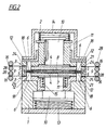
- the illustrated device forms a press insert from a Lower part 1 and an upper part 2, which parts 1, 2, each with a punch press tool 3 are provided.
- the punching tools 3 each have a die 4 arranged with openings 5 for the lower part 1 and the upper part 2 Stamp 6 on.
- the die 4 of the lower part 1 forms a centering recording 7 for a support ring 8, which extends over radially projecting driver 9 on the outer circumference the recording 7 centered. It does not need to be highlighted to be that a centering of the support ring 8 also on his Inner diameter can be done.
- the matrices 4 are about a cylindrical guide body 10 in a hold-down 11 stop limited mounted axially displaceable.
- the passages 12 for the punch 6 having down device 11 are coaxially displaceable in the associated lower or upper part 1, 2 out and supported Compression springs 13 and 14 on the lower part 1 and the upper part 2 from. While the Compression spring 14 in the upper part 2 acts directly on the hold-down 11, is the hold-down 11 of the lower part 1 on the cylindrical guide body 10th the die 4 is acted upon by the compression spring 13. Since between the die 4 and the hold-down 11 of the lower part 1, an opening spring 15 is provided, First, the opening spring 15 must be overcome before the hold-down 11 can be pressed against the die 4 of the lower part 1.
- the cutting guide so to choose is that the newly cut end of the tape again forms abutting edges 22 and between these abutting edges 22 has an edge profile 23 which is connected to the adapted by the Reibbelagsegmente 18 ring is adapted.
- a discharge device which is a gripping or engraving tool has, with the help of the end pieces 21 in the region of the projecting Webs 27 between the front and rear abutting edges 22 detected and in Direction of these abutting edges from the guide gap 17 between holddown 11 and die 4 can be removed
- the invention is of course not on the illustrated embodiment limited, so could for example the number of Reibbelagbs be changed, bearing in mind that with increasing number of Reibbelagb sectionsn the cut waste can be reduced.
- the design versions can be modified in very different ways because It's all about, a common punching tool for all over distributed the circumference of the support ring, the Reibbelagsegmente one side supplying Reibbelagb species available
Landscapes
- Engineering & Computer Science (AREA)
- General Engineering & Computer Science (AREA)
- Mechanical Engineering (AREA)
- Braking Arrangements (AREA)
- Application Of Or Painting With Fluid Materials (AREA)
- Perforating, Stamping-Out Or Severing By Means Other Than Cutting (AREA)
Description
- Fig. 1
- eine erfindungsgemäße Vorrichtung zum Aufbringen von Reibbelagsegmenten auf einen Tragring mit geöffneten Stanzwerkzeugen in einem schematischen Axialschnitt,
- Fig. 2
- diese Vorrichtung mit geschlossenen Stanzpreßwerkzeugen und
- Fig. 3
- einen Schnitt nach der Linie III-III der Fig. 1, allerdings nach einem Stanzvorgang.
Claims (10)
- Verfahren zum Aufkleben von Reibbelagsegmenten (18) auf einen Tragring (8), wobei die Reibbelagsegmente (18) aus einem bandförmigen, dem Tragring (8) auf der zu beklebenden Ringseite zugeführten Reibbelag mit Hilfe von Stempeln (6) eines Stanzpreßwerkzeuges (3) ausgestanzt und an den Tragring (8) angedrückt werden, und wobei dem Tragring (8) über den Umfang verteilt mehrere Reibbelagbänder(16) radial zugeführt werden, aus denen Reibbelagsegmente (18) mit Hilfe der Stempel (6) ausgestanzt und an den Tragring (8) angedrückt werden, dadurch gekennzeichnet, daß aus den im Bereich des äußeren Umfanges des Tragringes (8) aneinanderstoßenden Reibbelagbändern (16) ein Ring von Reibbelagsegmenten (18) mit Hilfe der Stempel (6) eines allen Reibbelagbändern (16) gemeinsamen Stanzpreßwerkzeuges (3) zugleich ausgestanzt und an den Tragring (8) angedrückt werden.
- Verfahren nach Anspruch 1, dadurch gekennzeichnet, daß dem Tragring (8) auf beiden Ringseiten über den Umfang verteilt mehrere Reibbelagbänder (16) zum Ausstanzen und Andrücken je eines Ringes von Reibbelagsegmenten (18) zugeführt werden.
- Vorrichtung zur Durchführung des Verfahrens nach einem der Ansprüche 1 oder 2 mit einer zentrierenden Aufnahme (7) für den Tragring (8) und mit einem der Aufnahme (7) zugeordneten Stanzpreßwerkzeug (3), das einerseits eine Matrize (4) mit mehreren entsprechend der vorgegebenen Verteilung der Reibbelagsegmente (18) auf dem Tragring (8) angeordnete Durchtrittsöffnungen (5) und anderseits durch diese Durchtrittsöffnungen (5) an einen in der Aufnahme (7) gehaltenen Tragring (8) anpreßbare Stempel (6) zum Ausstanzen von Reibbelagsegmenten (18) aus einem bandförmigen Reibbelag aufweist, der auf der der Aufnahme (7) abgekehrten Seite der Matrize (4) dem Stanzpreßwerkzeug (3) über einen radial zur Zentrierungsachse ausgerichteten Schrittförderer zuführbar und mittels eines Niederhalters (11) an die Matrize (4) andrückbar ist, dadurch gekennzeichnet, daß mehrere über den Umfang der Aufnahme (7) verteilte Schrittförderer für je ein Reibbelagband (16) vorgesehen sind, daß den Reibbelagbändern (16) ein gemeinsames Stanzpreßwerkzeug (3) zum gleichzeitigen Ausstanzen und Andrücken der Reibbelagsegmente (18) aus den einzelnen Reibbelagbändern (16) zugeordnet ist, daß sich die Längsrandverläufe benachbarter Reibbelagbänder (16) außerhalb des Ringes der Durchtrittsöffnungen (5) bzw. der Stempel (6) des Stanzpreßwerkzeuges (3) schneiden und daß der Niederhalter (11) oder die Matrize (4) im Bereich jedes Reibbelagbandes (16) außerhalb des Ringes der Durchtrittsöffnungen (5) bzw. der Stempel (6) eine in ihrem Verlauf an die innere Umrißlinie dieses Ringes angepaßte Schneide (24) bildet, die mit Abstand vor dem jeweiligen Längsrand (19) der Reibbelagbänder (16) in einen radialen, die Stoßkante (22) zum benachbarten Reibbelagband (16) ausschneidenden Endabschnitt (26) ausläuft.
- Vorrichtung nach Anspruch 3, dadurch gekennzeichnet, daß dem Stanzpreßwerkzeuge (3) auf der einen Seite des Tragringes (8) ein gleichartiges Stanzpreßwerkzeug (3) zum jeweils gemeinsamen Ausstanzen von Reibbelagsegmenten (18) aus mehreren radial zugeführten Reibbelagbändern (16) auf der anderen Tragringseite gegenüberliegt, wobei die Aufnahme (7) für den Tragring (8) die Matrize (4) für eines dieser Stanzpreßwerkzeuge (3) bildet.
- Vorrichtung nach den Ansprüchen 3 und 4, dadurch gekennzeichnet, daß die beiden Stanzpreßwerkzeuge (3) den Ober- und Unterteil (2, 1) eines Presseneinsatzes bilden, wobei jeweils die Matrize (4) im zugehörigen Niederhalter (11) axial verstellbar gelagert ist, während sich der im stempeltragenden Ober- bzw. Unterteil (2, 1) axial verschiebbare Niederhalter (11) gegenüber dem Ober- bzw. Unterteil (2, 1) federnd abstützt.
- Vorrichtung nach Anspruch 5, dadurch gekennzeichnet, daß zumindest zwischen der Matrize (4) und dem Niederhalter (11) des den Unterteil (1) bildenden Stanzpreßwerkzeuges (3) eine Öffnungsfeder (15) vorgesehen ist.
- Vorrichtung nach einem der Ansprüche 3 bis 6, dadurch gekennzeichnet, daß in den Zwickelbereichen zwischen benachbarten Reibbelagbändern (16) Abführeinrichtungen für den Schnittabfall der Reibbelagbänder (16) vorgesehen sind.
- Vorrichtung nach Anspruch 7, dadurch gekennzeichnet, daß die Abführeinrichtungen für den Schnittabfall der Reibbelagbänder (16) in Richtung der Stoßkanten (22) verfahrbare Greif- oder Stichwerkzeuge für den Schnittabfall aufweisen.
- Vorrichtung nach einem der Ansprüche 3 bis 8, dadurch gekennzeichnet, daß die Stempel (6) des Stanzpreßwerkzeuges (3) bzw. der Stanzpreßwerkzeuge (3) elektrisch beheizbar sind.
- Vorrichtung nach einem der Ansprüche 3 bis 9, dadurch gekennzeichnet, daß die Stempel (6) des Stanzpreßwerkzeuges (3) bzw. der Stanzpreßwerkzeuge (3) Prägeleisten zum Einprägen von Ölnuten in die Reibbelagsegmente (18) aufweisen.
Priority Applications (1)
| Application Number | Priority Date | Filing Date | Title |
|---|---|---|---|
| AT00890006T ATE271198T1 (de) | 1999-02-16 | 2000-01-10 | Verfahren und vorrichtung zum aufkleben von reibbelagssegmenten auf einen tragring |
Applications Claiming Priority (2)
| Application Number | Priority Date | Filing Date | Title |
|---|---|---|---|
| AT23799 | 1999-02-16 | ||
| AT0023799A AT408479B (de) | 1999-02-16 | 1999-02-16 | Verfahren und vorrichtung zum aufkleben von reibbelagsegmenten auf einen tragring |
Publications (2)
| Publication Number | Publication Date |
|---|---|
| EP1030075A1 EP1030075A1 (de) | 2000-08-23 |
| EP1030075B1 true EP1030075B1 (de) | 2004-07-14 |
Family
ID=3485200
Family Applications (1)
| Application Number | Title | Priority Date | Filing Date |
|---|---|---|---|
| EP00890006A Expired - Lifetime EP1030075B1 (de) | 1999-02-16 | 2000-01-10 | Verfahren und Vorrichtung zum Aufkleben von Reibbelagssegmenten auf einen Tragring |
Country Status (3)
| Country | Link |
|---|---|
| EP (1) | EP1030075B1 (de) |
| AT (2) | AT408479B (de) |
| DE (1) | DE50007031D1 (de) |
Families Citing this family (4)
| Publication number | Priority date | Publication date | Assignee | Title |
|---|---|---|---|---|
| JP4514249B2 (ja) | 1999-05-14 | 2010-07-28 | Nskワーナー株式会社 | 摩擦板の製造方法及び製造装置 |
| KR102148409B1 (ko) * | 2012-10-02 | 2020-08-26 | 섀플러 테크놀로지스 아게 운트 코. 카게 | 마찰 라이닝 지지대에 마찰 라이닝 부재들을 부착하는 방법 및 설비 |
| DE102015224366A1 (de) * | 2015-12-04 | 2017-06-08 | Schaeffler Technologies AG & Co. KG | Verfahren zum Anbringen von Reibbelagelementen an einem Reibbelagträger |
| CN115199686B (zh) * | 2022-07-15 | 2023-10-20 | 杭州萧山红旗摩擦材料有限公司 | 工程车桥式高碳制动器摩擦片及加工工艺 |
Family Cites Families (2)
| Publication number | Priority date | Publication date | Assignee | Title |
|---|---|---|---|---|
| DE69212310T2 (de) * | 1992-08-06 | 1996-12-12 | Fcc Hamamatsu Kk | Verfahren und Vorrichtung zum Herstellen von Kupplungsreibscheiben |
| US5776288A (en) * | 1996-05-07 | 1998-07-07 | Automotive Composites Company | Method and apparatus for lined clutch plate |
-
1999
- 1999-02-16 AT AT0023799A patent/AT408479B/de not_active IP Right Cessation
-
2000
- 2000-01-10 EP EP00890006A patent/EP1030075B1/de not_active Expired - Lifetime
- 2000-01-10 DE DE50007031T patent/DE50007031D1/de not_active Expired - Lifetime
- 2000-01-10 AT AT00890006T patent/ATE271198T1/de active
Also Published As
| Publication number | Publication date |
|---|---|
| EP1030075A1 (de) | 2000-08-23 |
| ATA23799A (de) | 2001-04-15 |
| ATE271198T1 (de) | 2004-07-15 |
| AT408479B (de) | 2001-12-27 |
| DE50007031D1 (de) | 2004-08-19 |
Similar Documents
| Publication | Publication Date | Title |
|---|---|---|
| DE102012108161A1 (de) | Verfahren zum Verbinden von Metallbändern | |
| DE102016118153A1 (de) | Werkzeug und Verfahren zumindest zum Handhaben von Werkstücken | |
| EP0739663B1 (de) | Bearbeitungsmaschine zum Umformen von Werkstücken | |
| WO1998050883A1 (de) | Verfahren zum herstellen von kunststoffkarten | |
| EP1030075B1 (de) | Verfahren und Vorrichtung zum Aufkleben von Reibbelagssegmenten auf einen Tragring | |
| DE3032016A1 (de) | Verfahren und vorrichtung zur herstellung von mit einstecktaschen aus folienmaterial beklebten blaettern | |
| DE19716816C2 (de) | Verfahren und Vorrichtung zum Trennen eines nach dem Innenhochdruck-Umformverfahren hergestellten Hohlkörpers | |
| EP1730767B1 (de) | Vorrichtung zur vereinzelung und positionierung von modulbrücken | |
| EP1035974A1 (de) | Vorrichtung mit einem zeichenträgermagazin und einem revolvermagazin zum einprägen von kennzeichen in sich bewegende teile | |
| DE3913960C2 (de) | ||
| WO2003104118A2 (de) | Mitnehmerelement | |
| DE2734884C2 (de) | ||
| DE2920073C2 (de) | Vorrichtung zum Verbinden mittels Nieten | |
| DE3425317C2 (de) | ||
| DE19816198C2 (de) | Nietverfahren und Nieteinrichtung zum Vernieten von mehreren, aus unterschiedlichen Werkstoffen bestehenden Werkstücken | |
| EP1638711B1 (de) | Prägemaschine und verfahren zum prägen von werkstücken | |
| EP0623454B1 (de) | Verfahren und Vorrichtung zur Herstellung eines Wabenkörpers | |
| EP0396072B1 (de) | Furnier-Zusammensetzmaschine | |
| EP1568451A1 (de) | Verfahren und Vorrichtung zum Stanzen eines Filtermaterials | |
| DE19622843A1 (de) | Vorrichtung zum Perforieren von Blechen | |
| DE19515724A1 (de) | Friktionswickelwelle zur Aufnahme mehrerer Wickelhülsen | |
| DE202023107442U1 (de) | Vorrichtung zum Einbringen einer Sicke in ein als Hohlkörper ausgebildetes Werkstück | |
| DE1949337A1 (de) | Rahmenform- und -auflegevorrichtung | |
| DE4318579A1 (de) | Vorrichtung zum Ablängen und Lochen von streifenförmigem Bandmaterial | |
| DE2063200A1 (de) | Vorrichtung zum Auflegen eines Profilrahmenbandes auf eine Schuhsohle bei gleichzeitigem Formen eines Profil rahmens auf deren Oberflache |
Legal Events
| Date | Code | Title | Description |
|---|---|---|---|
| PUAI | Public reference made under article 153(3) epc to a published international application that has entered the european phase |
Free format text: ORIGINAL CODE: 0009012 |
|
| AK | Designated contracting states |
Kind code of ref document: A1 Designated state(s): AT DE GB IT |
|
| AX | Request for extension of the european patent |
Free format text: AL;LT;LV;MK;RO;SI |
|
| 17P | Request for examination filed |
Effective date: 20010212 |
|
| AKX | Designation fees paid |
Free format text: AT DE GB IT |
|
| 17Q | First examination report despatched |
Effective date: 20020321 |
|
| GRAP | Despatch of communication of intention to grant a patent |
Free format text: ORIGINAL CODE: EPIDOSNIGR1 |
|
| GRAS | Grant fee paid |
Free format text: ORIGINAL CODE: EPIDOSNIGR3 |
|
| GRAA | (expected) grant |
Free format text: ORIGINAL CODE: 0009210 |
|
| AK | Designated contracting states |
Kind code of ref document: B1 Designated state(s): AT DE GB IT |
|
| REG | Reference to a national code |
Ref country code: GB Ref legal event code: FG4D Free format text: NOT ENGLISH |
|
| REF | Corresponds to: |
Ref document number: 50007031 Country of ref document: DE Date of ref document: 20040819 Kind code of ref document: P |
|
| GBT | Gb: translation of ep patent filed (gb section 77(6)(a)/1977) | ||
| PLBE | No opposition filed within time limit |
Free format text: ORIGINAL CODE: 0009261 |
|
| STAA | Information on the status of an ep patent application or granted ep patent |
Free format text: STATUS: NO OPPOSITION FILED WITHIN TIME LIMIT |
|
| 26N | No opposition filed |
Effective date: 20050415 |
|
| PGFP | Annual fee paid to national office [announced via postgrant information from national office to epo] |
Ref country code: IT Payment date: 20160119 Year of fee payment: 17 Ref country code: DE Payment date: 20160215 Year of fee payment: 17 |
|
| PGFP | Annual fee paid to national office [announced via postgrant information from national office to epo] |
Ref country code: GB Payment date: 20160128 Year of fee payment: 17 |
|
| PGFP | Annual fee paid to national office [announced via postgrant information from national office to epo] |
Ref country code: AT Payment date: 20170124 Year of fee payment: 18 |
|
| REG | Reference to a national code |
Ref country code: DE Ref legal event code: R119 Ref document number: 50007031 Country of ref document: DE |
|
| GBPC | Gb: european patent ceased through non-payment of renewal fee |
Effective date: 20170110 |
|
| PG25 | Lapsed in a contracting state [announced via postgrant information from national office to epo] |
Ref country code: GB Free format text: LAPSE BECAUSE OF NON-PAYMENT OF DUE FEES Effective date: 20170110 Ref country code: DE Free format text: LAPSE BECAUSE OF NON-PAYMENT OF DUE FEES Effective date: 20170801 |
|
| PG25 | Lapsed in a contracting state [announced via postgrant information from national office to epo] |
Ref country code: IT Free format text: LAPSE BECAUSE OF NON-PAYMENT OF DUE FEES Effective date: 20170110 |
|
| REG | Reference to a national code |
Ref country code: AT Ref legal event code: MM01 Ref document number: 271198 Country of ref document: AT Kind code of ref document: T Effective date: 20180110 |
|
| PG25 | Lapsed in a contracting state [announced via postgrant information from national office to epo] |
Ref country code: AT Free format text: LAPSE BECAUSE OF NON-PAYMENT OF DUE FEES Effective date: 20180110 |